Search results
Query: soldering coax
Links: 8 | Categories: 0
-
 A 9 dB gain 70cm collinear antenna construction is detailed, utilizing eight half-wavelength sections of _RG58/U_ coaxial cable. The design incorporates specific calculations for velocity factor (0.66 for RG58/U) to determine precise element lengths, such as 223mm for a half-wavelength at 444 MHz. A quarter-wave radiating element of #16 solid wire, 169mm long, is added to the top, and a 160mm aluminum tube acts as a quarter-wave counterpoise at the feed point. RF choke baluns, constructed from three _FT50-43_ toroids, are positioned a half-wavelength from the feed point to mitigate common mode current. Assembly involves soldering the coax sections in series, followed by SWR testing during construction and final mounting within a ¾-inch PVC pipe. The article suggests using four half-wave elements for a shorter antenna, noting a potential slight increase in SWR, which can be mitigated with quarter-wave ground radials. The design principles and formulas are scalable for other VHF/UHF bands like 6m, 2m, or 1¼m, providing a versatile homebrew solution for enhanced gain.
 -
 The Flower Pot Antenna project details a portable dual-band antenna primarily operating on 10 meters, with secondary resonance near the 30-meter band. Construction involves winding RG58 coaxial cable uniformly around a large plastic flower pot, approximately 70cm high with a 60cm top diameter. The design eliminates the need for radials, contributing to its compact and lightweight nature. Key construction steps include soldering the inner conductor to the shield at one end of the wound cable and connecting the wound cable's shield to the rig cable's inner conductor at the base. An LC network, comprising a variable capacitor (0-200pF) and an inductor (10 coils, 5cm diameter, 2mm wire), is inserted between the wound cable's inner conductor and the rig cable's shield. Tuning is performed with an antenna analyzer, adjusting cable length and the variable capacitor for optimal impedance on 10 meters. The antenna performs effectively when installed horizontally.
 -
 An illustrated and complete guide to soldering PL-256 coax plugs
 -
 Demonstrates various practical amateur radio projects and technical discussions through video episodes. One episode details cutting and retuning a _1/4 wave shorted stub_ from 101.7 MHz to 107.5 MHz to safeguard a transmitter's driver stage, alongside insights into advanced _160-meter antenna systems_ like eight-circle arrays and beverage antennas. Another segment covers upgrading firmware on an _ATS-20+_ receiver using AverDudes for improved display and functionality, and a detailed guide on using D-Star DR mode on an _ICOM ID-52A_ for international repeater programming. Additional content includes a deep dive into _OpenHamClock_ as a potential replacement for the HamClock project, updates on _Raspberry Pi 5_ running Trixie OS, and a review of the Choyong LC90 Internet radio with AI integration. The series also features "Ham College" episodes, which meticulously prepare viewers for the Technician Exam by covering topics such as antenna and transmission line measurements, SWR interpretation, and the functions of basic electronic components like rectifiers, relays, and transistors. Practical advice on coaxial cable characteristics, dummy loads, and proper soldering techniques is also provided.
 -
 This web article details the construction of a 4-meter band coaxial dipole antenna, designed for operation between **70.000 MHz and 70.500 MHz**. The resource provides a bill of materials and step-by-step assembly instructions for a half-wave dipole constructed from _RG-58_ coaxial cable. The design specifies a direct 50 ohm feedpoint impedance, eliminating the need for an external matching network. Construction photographs illustrate the stripping and soldering processes for the coaxial cable elements, ensuring proper electrical connection and physical integrity. The article includes specific dimensions for the radiating elements, derived from calculations for the 70 MHz band. The project outlines the physical dimensions required for resonance at 70 MHz, with the outer braid forming one half and the inner conductor forming the other. The feedline connection is directly to the coaxial dipole's center, maintaining a 50 ohm characteristic impedance. While the article does not present SWR plots or VNA sweeps, it focuses on the mechanical construction and dimensional accuracy for achieving a functional 4-meter dipole. The design is intended for fixed station use, with no specific mention of polarization or height above ground, but implies a standard horizontal orientation for dipole operation. DXZone Focus: Web Article | 4m Coaxial Dipole | Construction Guide | 50 ohm Feed
 -
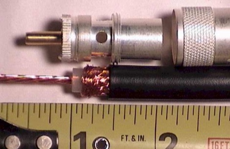
 Coaxial cable stripping for PL-259 connectors requires precise measurements to ensure optimal RF performance and mechanical integrity. For RG-8X, the outer jacket is stripped 1/2 inch, the braid 5/16 inch, and the dielectric 1/8 inch, leaving the center conductor exposed. RG-58 preparation involves a 1/2 inch jacket strip, 1/4 inch braid strip, and 1/8 inch dielectric strip. These specific dimensions facilitate proper soldering and crimping, minimizing impedance discontinuities at the connector interface. Different coaxial cable types, such as RG-8 and RG-213, necessitate varied stripping lengths due to their construction. The _PL-259_ connector, a common UHF type, relies on these exact preparations for a secure fit and low-loss connection. Incorrect stripping can lead to high SWR, RF leakage, and mechanical failure, impacting overall station efficiency. The guide details these critical dimensions for several popular coax cables. Using a dedicated _coax stripper_ tool or precise measurements with a utility knife improves consistency.
 -
 Building an End-Fed Half-Wave (EFHW) antenna from a kit, as detailed by Frank Bontenbal, PA2DKW, with process photos by Bob Inderbitzen, NQ1R, offers a practical approach for hams. This specific kit, a collaboration between ARRL and HF Kits, targets 10, 15, 20, and 40 meters, making it a versatile option for HF operations. Unlike a center-fed dipole, the EFHW is a half-wavelength antenna fed at one end, which simplifies deployment, particularly for portable use. The construction guide meticulously outlines the assembly of the 49:1 impedance matching network, crucial for transforming the antenna's high impedance (around 2,500 Ohms) to a transceiver-friendly 50 Ohms. Steps include preparing the enclosure by drilling holes for the coaxial connector and antenna connections, followed by the precise winding of enameled copper wire onto a toroid to create the transformer. The guide emphasizes careful insulation removal and soldering for reliable connections. Final assembly involves integrating a 100 pF capacitor for higher band compensation, soldering the transformer's primary and secondary sides, and conducting SWR tests with a 2K7 resistor or a half-wavelength wire. The document also provides examples of wire lengths for different bands, such as 16 feet for 10 meters or 66 feet for 40 meters, demonstrating the transformer's adaptability for various half-wavelength configurations.
 -
 Presents a detailed construction guide for a 9 dB, 70cm collinear antenna, utilizing readily available _RG58/U_ coaxial cable and PVC pipe for housing. The resource outlines the critical calculations for ½ wavelength sections at 444 MHz, incorporating the coaxial cable's velocity factor of 0.66, which yields a section length of 223 millimeters. It specifies the preparation and soldering of eight such half-wavelength sections, each cut to 231mm to allow for trimming, forming the core of the array. Further instructions detail the integration of a ¼ wave element (169mm #16 solid wire) at the top and a ¼ wave aluminum tube (160mm, 5/16 inch) at the bottom, crimped to the feed point's braid. The guide also addresses RF common mode current suppression by suggesting the use of _FT50-43_ toroids on the feedline. Final assembly steps cover mounting the antenna within ¾" PVC pipe using a wooden dowel, waterproofing connections, and initial SWR checks. The article also discusses scaling the design for different element counts and other VHF/UHF bands.