Search results
Query: transceiver 10m
Links: 17 | Categories: 0
-
 Optimizing antenna portability for QRP field operations often involves trade-offs between efficiency and physical footprint. The PAC-12 antenna project addresses this by presenting a **multi-band portable vertical** design, specifically tailored for amateur radio operators who travel frequently and utilize compact QRP transceivers like the Elecraft K1/K2 or Yaesu FT-817. This design emphasizes ease of homebrewing using readily available hardware store components, allowing for customizability and repair in the field. The project details the construction of a sectional aluminum rod base, interchangeable loading coils for various HF bands, and a telescoping whip. Key components include 1/4-inch aluminum rod, PVC risers for coil forms, and a BNC feedpoint insulator. The design prioritizes a breakdown length of 12 inches or less, making it highly packable for travel, while still achieving competitive efficiency, as demonstrated by its first-place finish in the HFPack antenna shootout at Pacificon 2001 against a 1/4-wavelength wire vertical. Comprehensive instructions cover whip preparation, **loading coil construction** with specific dimensions for bands from 40m to 10m (with an untested 80m approximation), base section fabrication, and feedpoint insulator assembly. The resource also includes guidance on radial deployment, threading aluminum rod, and showcases various PAC-12 builds by NJQRP Club members, illustrating its adaptability and widespread adoption among QRP enthusiasts.
 -
 Presents the design and construction of an automatically tuned 7-30 MHz mobile HF vertical antenna, originally published in _QEX / Communication Quarterly_ in 2003. The resource details a base-loaded vertical antenna system that mounts on a vehicle's roof, incorporating a variable inductor as its loading coil. A three-legged chariot, driven by a modified model airplane servo, travels inside the coil to adjust inductance. The control unit, featuring a _Basic Stamp microcontroller_ and SWR sensor, emulates a Kenwood AT-50 tuner for seamless integration with a _Kenwood TS-50_ transceiver, allowing automatic tuning across all ham bands from 40 to 10 meters. The project emphasizes practical application, providing a solution to the narrow-banded nature of mobile HF antennas and the inconvenience of manual band changes. It achieves a maximum SWR of 1.3:1 across its operating range. The mechanical design is thoroughly documented with detailed drawings, including a full-resolution GIF and AutoCAD R14 DWG files, illustrating components like the stainless steel whip, PVC coil tube, and the servo-driven chariot mechanism. Construction requires a lathe, but the author notes it can be accomplished with a hobby lathe, making it accessible to those with moderate mechanical skills.
 -
 Presents the design and construction of the OK2FJ Bigatas, a portable, automatically tuned vertical antenna covering 80 through 10 meters. It details two distinct control systems: one utilizing BCD band data from Yaesu FT-857/897 transceivers, and another employing voltage level sensing for the Yaesu FT-817. The resource provides specific instructions for building the antenna's radiating element, loading coil with switchable taps, and the control circuitry, emphasizing the use of readily available components. The article outlines the physical construction of the antenna, including the use of duralumin tubes for the radiator and a PVC tube for the coil form. It specifies coil winding details, tap points, and the integration of radial wires for ground plane operation. The control electronics section provides schematics and component lists for both the BCD decoder (using a 74LS42 IC) and the voltage comparator (using an _LM3914_ bargraph driver), enabling rapid, automatic band switching without the minute-long tuning delays common in other systems. Crucially, the antenna achieves rapid band changes, with typical SWR values centered on common operating segments, such as **3.7 MHz** for 80m SSB. It also discusses modifications for CW operation on 80m and the trade-offs between antenna efficiency and full-range automatic tuning on higher HF bands, where manual adjustment of radiator length is suggested for optimal performance on 15m, 12m, and 10m. The resource includes construction photos and a discussion of cable requirements for reliable operation.
 -
 The Q-signal **QRP** signifies a request to reduce power, and in amateur radio, it defines operating with 5 watts or less for CW and 10 watts or less for SSB. This article addresses common inquiries from new hams regarding the practice, its benefits, and implementation methods. It explains how a 5-watt QRP signal, compared to a 100-watt signal, typically results in only a 13dB drop in signal strength, equating to about two S-units, still providing solid copy under most conditions. Hams choose QRP for various reasons, including seeking a greater challenge in DXing or contesting, reducing band interference, or enabling portable field operations with lightweight, battery-efficient equipment. A modern single-band CW transceiver, key, and antenna can fit into a pocket, offering receiver performance comparable to commercial rigs and extended operation on a small battery. This portability facilitates operations in remote locations where higher-power setups are impractical. Operating QRP can involve simply reducing power on an existing commercial HF rig or building a dedicated QRP transceiver from a kit, such as the **Wilderness Radio SST** with its 2-watt output and 15mA receive current draw. While SSB is viable, CW remains the most popular and efficient mode for QRP due to its superior signal-to-noise ratio. The article lists common QRP calling frequencies across 160m through 10m bands for both CW and SSB, and highlights organizations like QRP ARCI and NorCal that support the QRP community.
 -
 Presents the Light Loop, a small magnetic loop antenna optimized for 40m through 10m operation, demonstrating its construction for portable QRP use. The design emphasizes lightweight materials and a compact form factor, making it suitable for handheld or backpack deployment during field activities. It details the primary radiating element, the coupling loop, and the variable capacitor required for resonance across the specified HF bands. The article provides specific component choices, such as the 1.5-inch diameter aluminum tubing for the main loop and the 10-365 pF variable capacitor for tuning. It discusses the importance of precise loop circumference and spacing for efficient impedance matching and bandwidth characteristics. The resource includes practical advice on achieving resonance and optimizing performance for low-power transceivers. Construction notes cover the mechanical assembly, including mounting the capacitor and feedpoint connections. It highlights the antenna's suitability for pedestrian mobile operations, offering a practical solution for HF communication without extensive setup. The design aims for a balance between portability and effective radiation on the lower HF bands.
 -
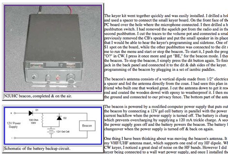 How to build a beacon keyer for 28 MHz using an old CB Radio transceiver, by Tom Sevart
 -
-
 Optimizing a G5RV or ZS6BKW multiband wire antenna for HF operation often involves addressing common SWR issues and understanding feedline characteristics. This resource chronicles the construction and performance evaluation of a G5RV, initially built for 80m, 40m, 15m, and 10m bands, by a newly licensed Foundation operator. The author details the selection of materials, including 3.5 mm stainless steel wire for the doublet arms and enameled copper wire for the open-wire feeder, and the initial decision to omit a balun based on common online information. The narrative highlights the initial disappointing performance, characterized by high receive noise and poor signal reports on 80 meters, despite the transceiver's internal ATU achieving a 1:1 match. This led to experimentation with a coax current balun and further research into G5RV myths, such as SWR claims and the necessity of a balun. The author then describes modifying the antenna to the ZS6BKW configuration, which involves specific changes to the doublet and feedline lengths, and integrating a 1:1 current balun wound on a ferrite toroid. The modifications resulted in improved reception and transmit performance across the bands.
 -
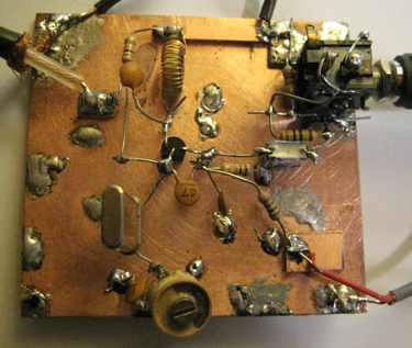
 A circuit for a 5 milliwatts super QRP morse code transceiver by VE2ZAZ
 -
 The X80 multi-band HF vertical antenna, a commercial iteration of the Rybakov design, exhibits a physical length of 5.5 meters, or approximately 18 feet, and is constructed from aluminum tubing. It operates as a non-resonant vertical, requiring an external antenna tuner for impedance matching across its intended operating frequencies. The antenna's design incorporates a 1:4 UNUN at its base, facilitating a nominal 50-ohm feed point impedance for the coaxial cable. Performance observations indicate effective operation on 40 meters, 20 meters, 15 meters, and 10 meters, with reduced efficiency on 80 meters and 160 meters due to its relatively short electrical length for these lower bands. Comparative analysis with a G5RV dipole and a half-wave end-fed antenna reveals the X80 offers a lower take-off angle, beneficial for DX contacts, particularly on the higher HF bands. Field tests conducted with an Icom IC-706MKIIG transceiver and an LDG AT-100ProII autotuner demonstrate the X80's ability to achieve acceptable SWR across 80m through 10m. The antenna's compact footprint and ease of deployment make it suitable for restricted spaces or portable operations, though its performance on 80 meters is noted as a compromise compared to full-size resonant antennas.
 -
 2 transistor transceiver for 28MHz CW
 -
 KN-Q10 Assembly Manual four band (3.5, 7, 14 & 21MHz) 5W SSB/CW transceiver kit Translated by BD6CR/4,
 -
 Documents the operational experiences and technical insights of amateur radio station VA3STL, offering a firsthand account of various on-air activities and equipment. The blog features a detailed narrative of a **QRP transatlantic QSO** on 12m SSB, achieving a 55 report with 10W to a mobile station in Italy using a homebrew 90ft doublet antenna. It also introduces the _Ten-Tec 539_ QRP HF transceiver, a 10W output rig covering 80m through 10m, designed for portable operations and featuring DSP and dual VFOs. The resource also delves into historical radio technology, specifically the "Gibson Girl" survival radio, an emergency transmitter operating on 500kHz (and later 8280/8364 kHz) with a hand-cranked generator and kite-deployed antenna. This section explores its origins from German designs and its use during World War II, including its distinctive curved shape for ergonomic hand-cranking. Further historical content includes a visit to Signal Hill in St. John's, Newfoundland, commemorating Marconi's reception of the first transatlantic radio signal in 1901. The post describes the Cabot Tower exhibit and the VO1AA station, highlighting the site's significance despite the thick fog during the visit. It also showcases a homebrewed _Marconi-style straight key_ by WB9LPU, crafted to celebrate the centenary of Marconi's achievement.
 -
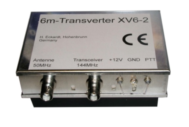 The XV4-10 is a linear transverter for the 4m band to be used with a 10m transceiver. Input frequency 29-30 MHz, output frequency 69.5-70.5 MHz
 -
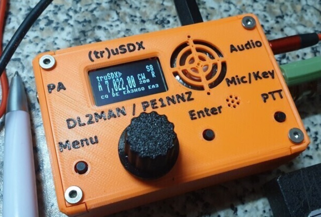 The (tr)uSDX is a 5-Band / Mulitmode QRP Transceiver in Pocket Format (90x60x30mm - 140g). It features a highly efficient Class E PA and Supports CW/LSB/USB and AM/FM. Right now it covers 80/60/40/30/20m and in Future there will be support for 17/15/12/10m
 -
 Integrating a _Software Defined Radio_ (SDR) into an existing ham radio setup involves connecting it with a standard transceiver (TRX), power amplifier (PA), and antennas. The core component is a splitter box that facilitates the connection between the TRX and the SDR, allowing for simultaneous operation without modifying existing equipment. In receive mode, the splitter ties the antenna inputs of both the TRX and a direct conversion receiver (DC RX) together. During transmission, the DC RX input is grounded via a fast telecom relay controlled by the transceiver's -SEND signal, incorporating a 10ms delay for safety. The splitter box includes a 3.7 dB input attenuator for impedance matching and acts as a protective fuse for the DC RX input. Ground loops are mitigated using common mode balun transformers, while the DC RX input is insulated with a broadband transformer. An audio switch box complements the setup, enabling users to listen to either the main transceiver, the SDR output, or both simultaneously. This configuration ensures noise immunity and safety, with the splitter housed in a screened box made from PCB material. On-air tests, such as the CQ WW 160m CW DX Contest, demonstrate the system's effectiveness, showcasing the SDR's ability to handle crowded band conditions with superior selectivity and dynamic range. The SDR's narrow bandwidth filters and waterfall display provide significant advantages, allowing operators to detect weak signals amidst strong interference. The integration of SDR with conventional radios offers enhanced operational flexibility and performance in challenging environments.
 -
 Presents DJ5IL's personal amateur radio station, detailing his journey as a licensed operator since 1973. The resource covers his **shack setup**, including an Elecraft K4D, Icom IC-7610, and various vintage transceivers like the Drake 2-B, along with a SPE Expert 1K-FA amplifier. Antenna systems include a PRO.SIS.TEL RD1524T rotary dipole for 40/20/15/10m at 15m height, an 18m vertical dipole with an SGC SG-230 tuner for 3.5-30 MHz, and an inverted-V dipole for 80m. The site features a **QSL gallery** showcasing his custom card designs and outlines his QSL policy, emphasizing the exchange of unique, personalized cards over generic confirmations. It also includes a detailed operator's biography, tracing his early fascination with radio, obtaining his license at 16, and memorable QSOs, such as a contact with his blood-relative W3NZ. The resource also delves into the historical significance of amateur radio's role in pioneering shortwave communication following the 1912 International Radiotelegraph Convention, which initially relegated amateurs to wavelengths of 200 meters and shorter. DJ5IL's philosophy on "ham spirit" is discussed, stressing the unpolitical nature of amateur radio as a global fraternity.