Search results
Query: led
Links: 937 | Categories: 21
Categories
- Radio Equipment > HF Amplifiers > Acom 1000
- Radio Equipment > HF Amplifiers > Ameritron ALS-600
- Technical Reference > Antenna Switch
- Radio Equipment > Antenna Analyzers > Array Solutions AIM 4170D
- Antennas > Bazooka
- Operating Modes > Satellites > Clubs
- Shortwave Radio > Clubs
- Operating Modes > Amateur Television > Clubs
- DX Resources > Contest Calendars
- Operating Modes > D-STAR > D-Star Clubs
- Radio Equipment > HF Transceivers > Icom IC-7700
- Radio Equipment > HF Transceivers > Icom IC-7851
- Technical Reference > Mic wiring
- Radio Equipment > Radio Equipment Reference
- Radio Equipment > Receivers
- CB Radio > References
- Radio Equipment > Reviews and Comparisons
- Ham Radio > Clubs > North America > USA > Vermont
- Radio Equipment > HF Transceivers > X1M
- Radio Equipment > HF Transceivers > XIEGU G90
- Radio Equipment > HF Transceivers > Yaesu FT-818
-
 This document provides comprehensive guidance on modeling and constructing multiband dipole antennas using traps. It addresses common segmentation issues in EZNEC modeling software, recommends optimal segment lengths for trap models, and compares trapped dipoles with paralleled multiband dipoles. While trap dipoles are significantly shorter, they exhibit lower gain and narrower bandwidth. Detailed instructions for building weatherproof coaxial traps include material lists, construction steps, and tuning methods. The guide notes that properly constructed coaxial traps introduce only minimal signal loss (0.6 dB) while offering practical multiband performance in a compact design.
 -
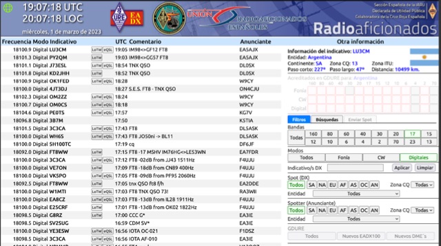 Operating on the HF and VHF bands, the URE WebCluster serves as a real-time DX spotting network for amateur radio operators. It aggregates DX spots from various sources, presenting them with detailed information such as DX callsign, frequency, mode, and spotter details. The platform integrates essential propagation data, including current solar indices like _K-index_ and _A-index_, alongside visual propagation maps, which are crucial for planning long-distance contacts. Users can submit new DX spots, contributing to the collective intelligence of the amateur radio community, and filter existing spots by band, mode, or callsign, enhancing operational efficiency. This resource enables operators to monitor band openings and identify active DX stations, significantly aiding in _DXCC_ pursuit and contest operations. The integration of solar-terrestrial data directly within the cluster interface allows for immediate correlation between propagation conditions and observed DX activity, a feature not universally present in all web clusters. By providing both raw spot data and contextual propagation information, the URE WebCluster offers a practical tool for real-time decision-making during operating sessions, allowing hams to quickly adapt to changing band conditions and target specific _DX_ entities.
 -
 Kanga Products offers a diverse range of kits and pre-built items for amateur radio operators, including Morse tutors, keys, antenna tuners, and dummy loads. Their products cater to both beginners and advanced users, with options for practice oscillators, receivers, and various electronic components. The company provides detailed instructions and supports DIY projects, making it a go-to for hobbyists seeking practical and educational tools.
 -
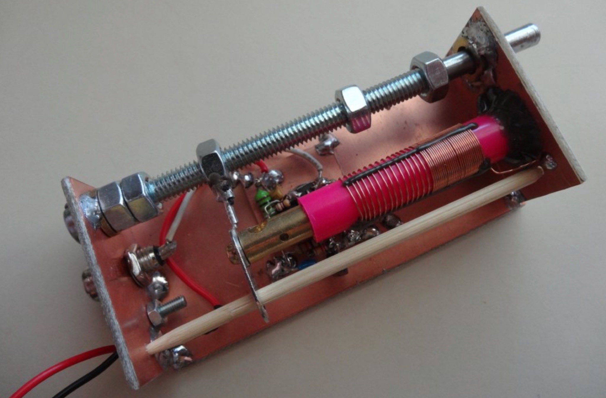 Learn about Permeability Tuned Oscillators (PTO) and why they are useful for ham radio operators. This page covers the mechanics of PTO tuning, the components involved, and how to wind the PTO inductor. Written by Andrew Woodfield ZL2PD, this resource provides a detailed guide for building and using a PTO oscillator in your amateur radio projects.
 -
 The article discusses the use of SDR# (SDR SHARP) software for SDR receivers, highlighting its Band Plan feature that visually represents RF spectrum allocations. The author modified SDR# to display detailed IARU HF band plans, creating three XML files for different IARU regions. These files include various operational modes and specific frequency allocations. Despite potential errors, the modifications aim to enhance the usability of SDR# for ham radio operators. The article includes references and download links for the XML files and IARU band plans.
 -
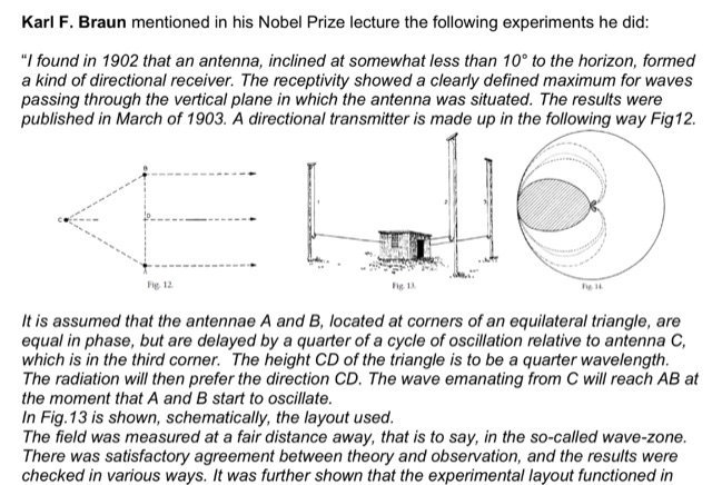 Phased array antennas are composed of multiple individual antenna elements that can have their phase and amplitude controlled to steer the main beam direction in real-time. They are used in radar, communications, and electronic warfare, and offer improved gain and reduced side lobes. A comprehensive document on Phased Arrays include techniques to increase the Antenna Gain and change the Radiation Pattern
 -
 This website serves as a platform for announcing satellite activities, allowing amateur radio operators to publicize their plans for upcoming scheduled passes. It also offers a useful scheduling feature that provides satellite pass information tailored to your location, which you can input by entering your locator.
 -
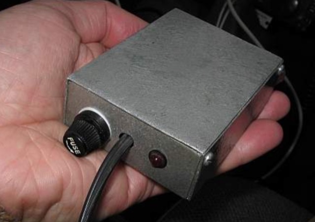 Well, firstly the 12 Volt source will typically vary anywhere from 11 Volt to 15 Volt, and then a battery needs a controlled charge current and voltage, which cannot result from connecting it directly to a voltage source.
 -
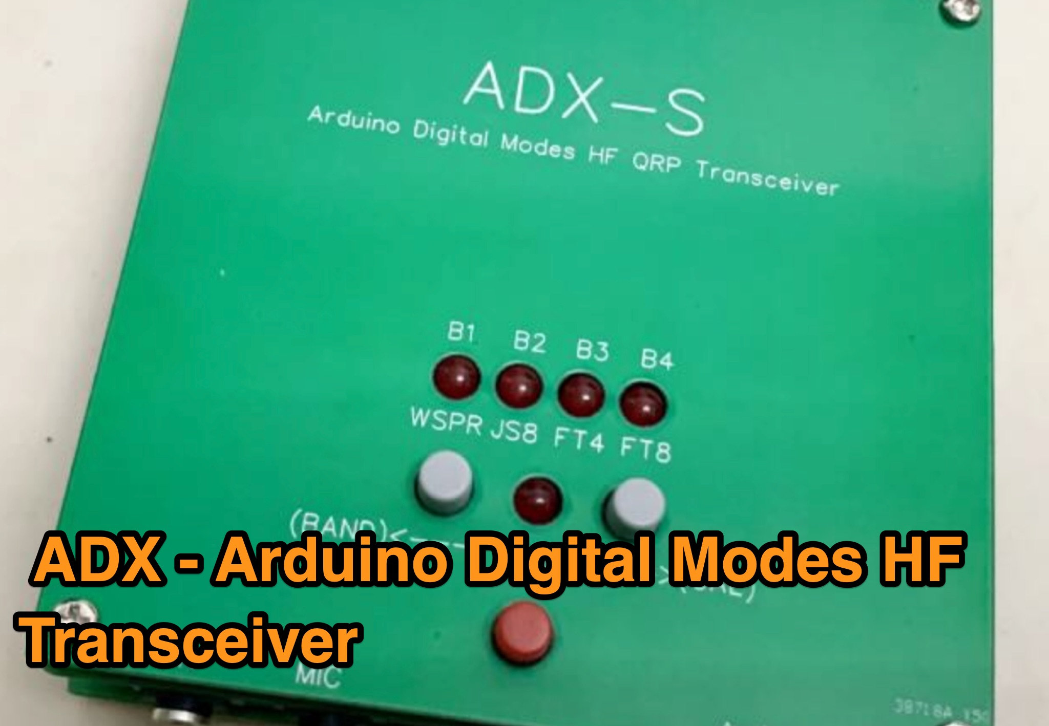 This page provides updates, manuals, and firmware for the ADX - Arduino Digital Modes HF Transceiver. Learn about calibration procedures, band display bug corrections, and important notes on the SI5351 library. The content includes a detailed build manual and firmware updates for the ADX, a mono band (actually quad band) digital modes optimized HF transceiver based on Arduino. Stay informed about the latest releases, bug fixes, and enhancements to improve your experience with the ADX transceiver.
 -
 Analyzes the operational dynamics of the _IARU R1 VHF contest_, the world's largest 2-meter contest, focusing on factors enabling top performers to maintain consistent results amidst declining overall activity. The resource investigates the physical constraints that limit higher point totals, examining how technical capabilities, increased interference, and evolving station setups contribute to contest outcomes. It provides insights into the strategic and technical aspects of achieving high scores, such as the **1,000,000+ point** totals observed from leading stations. Compares the performance of various stations over time, highlighting the sustained success of top contenders and speculating on future trends in VHF contesting. The analysis delves into specific operational strategies and equipment choices that differentiate high-scoring stations, offering a detailed look at the competitive landscape. It also considers the impact of propagation conditions and operator skill on final scores, providing a comprehensive overview of the contest's intricate mechanics and the pursuit of maximum QSO points.
 -
 The MSF radio signal is a dedicated standard-frequency and time broadcast that provides an accurate and reliable source of UK civil time. It is available 24 hours a day across the whole of the UK and beyond. The signal operates on a frequency of 60 kHz and carries a time and date code that can be received and decoded by a wide range of readily-available radio-controlled clocks.
 -
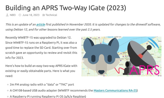 The guide outlines necessary components, including a 2m FM analog radio, USB audio adapter, and Raspberry Pi. Building a cable to connect these elements is assumed, as is knowledge of Raspberry Pi OS installation.
 -
 This PDF file provides detailed information on HF propagation for ham radio operators. It covers the principles of how radio signals travel over long distances, including factors that affect signal strength and propagation. The content is useful for hams looking to improve their understanding of radio communication and optimize their transmissions. Whether you're a beginner or an experienced operator, this resource offers valuable insights into HF propagation that can enhance your communication skills and efficiency on the airwaves.
 -
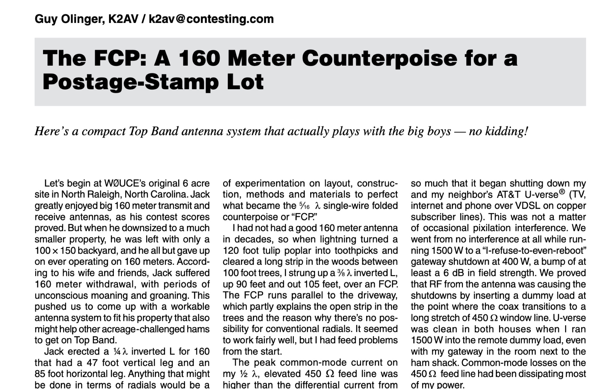 The article by Guy Olinger, K2AV, published in the May/June 2012 National Contest Journal, introduces the Folded Counterpoise (FCP), a compact 516-foot single-wire counterpoise elevated at 8 feet, designed for 160-meter operations on small lots like 100x150-foot backyards. Originating from efforts to revive Top Band for W0UCE on a postage-stamp property, the FCP uses strategic folds to cancel ground fields within 33 feet of center, minimizing losses to 0.13-0.53 dB—outperforming sparse or on-ground radials by up to 15 dB in poor soil—while mimicking opposed radials for efficient feedpoint impedance. Paired with a critical 1:1 or 4:1 isolation transformer (e.g., trifilar on T300-2 toroid) to block common-mode currents on coax feeds, it delivers proven results: K2AV's #8 North America low-power contest score, 7+ dB gains at W4KAZ and K5AF, and over 10,000 global web hits for DIY instructions using bare 12 AWG wire and weatherproof enclosures. Ideal for acreage-challenged hams, the FCP also excels on 80 meters with scaled dimensions, offering a low-loss alternative where full radials are impractical
 -
 A 5/8-wavelength vertical antenna for 2-meter FM operation is detailed, focusing on eliminating loading coils by utilizing a series inductor to cancel capacitive reactance at the feed point, thereby presenting a 50-ohm impedance match. The design illustrates three basic configurations, including a method employing a short-circuited coaxial stub for inductance, as implemented by K4LPQ. An alternative design is presented where the center conductor of the stub is extended one-quarter wavelength, creating a signal-frequency short and allowing for an insulated wire stub to develop the required series inductance. The article provides electrical theory and mechanical considerations for building the antenna, emphasizing the adjustment of stub length for proper impedance matching. This technical documentation is intended for amateur radio operators interested in homebrewing VHF antennas, offering practical insights into impedance matching techniques for vertical radiators.
 -
 This page contains detailed notes on repairing and aligning the Kenwood TS-440S HF radio. The author shares their experience repairing several TS-440S radios, highlighting common issues and repair techniques. The page also discusses parts availability, modifications, and the radio's performance for digital modes like FT8 and JT65. Aimed at ham radio operators interested in repairing and maintaining vintage HF radios, this page provides valuable insights and tips for working on the Kenwood TS-440S.
 -
 Paul McMahon details the design and construction of a four-element Yagi antenna for the 50-52.5 MHz range, published in Amateur Radio Magazine (Dec 2011). The antenna, featuring a raised driven element and a capacitive/DC connection using copper strips, maintains consistent VSWR and performance despite two years of weather exposure. The design utilizes inexpensive plumbing conduit for the boom and provides detailed construction guidelines, parts lists, and performance analysis through 4NEC2 simulations.
 -
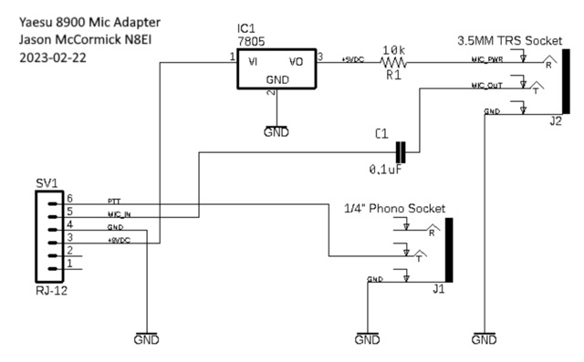 Explore the process of creating a custom adapter for the Yaesu FT-8900 radio with a non-standard mic port. The article guides users through understanding the reversed pin-out of the RJ-12 connector on the 8900, providing a detailed circuit for adapting the voltage for electret-based mics. With a list of required parts and construction tips, this DIY project ensures seamless compatibility with standard electric headset mics.
 -
 **APRS TX I-Gate with APRX and the Universal Radio Controller** This project explores the creation of an APRS TX I-Gate to improve message delivery in amateur radio communications. Initial experiments involved configuring a picoAPRS v4 and later a G1LRO Universal Radio Controller (URC) with a Quansheng UV-K5 as digipeaters. While both setups successfully retransmitted signals, they failed to receive incoming APRS messages. To address this, a Raspberry Pi Zero running Debian and APRX-2.9 was repurposed to provide network connectivity, transforming the URC into an effective TX I-Gate for seamless APRS message handling.
 -
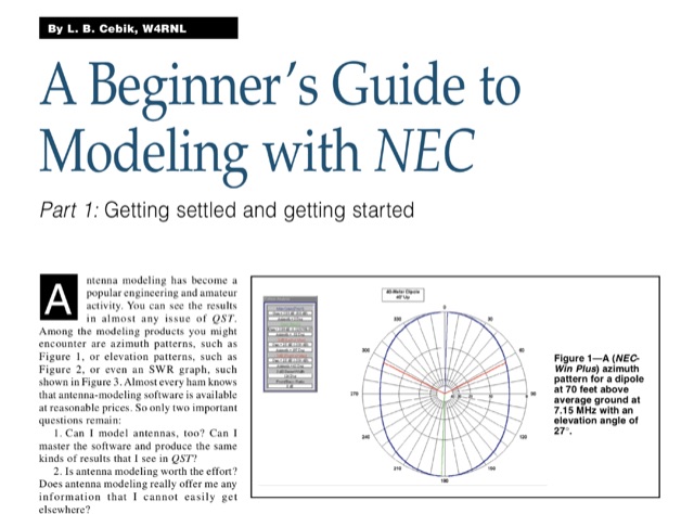 Antenna modeling is an essential technique for both amateur and professional engineers, enabling precise analysis of antenna performance. This guide, published on 4 different QST articles by L. B. Cebik, introduces NEC-2, a widely used public domain software for modeling antennas, focusing on its capabilities and practical applications. The series aims to demystify the modeling process, providing foundational knowledge and techniques for effective antenna design. Key concepts include understanding the method of moments and the importance of segmenting antenna elements. By mastering these principles, users can enhance their comprehension of antenna behavior and optimize their designs for improved performance.
 -
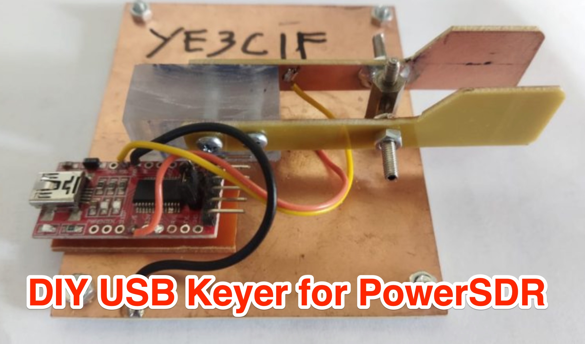 Learn how to create a USB Keyer for PowerSDR to enhance your CW experience. This article provides a step-by-step guide using affordable materials like a USB to TTL Module (FT232RTL) and a Keyer iambic. The tutorial includes a detailed wiring diagram and instructions for configuring the Keyer in the PowerSDR menu. The author also shares a helpful video demonstration to ensure smooth operation. Whether you're a seasoned ham operator or new to CW, this DIY project can improve your radio setup. Follow these instructions to build your USB Keyer and elevate your PowerSDR experience.
 -
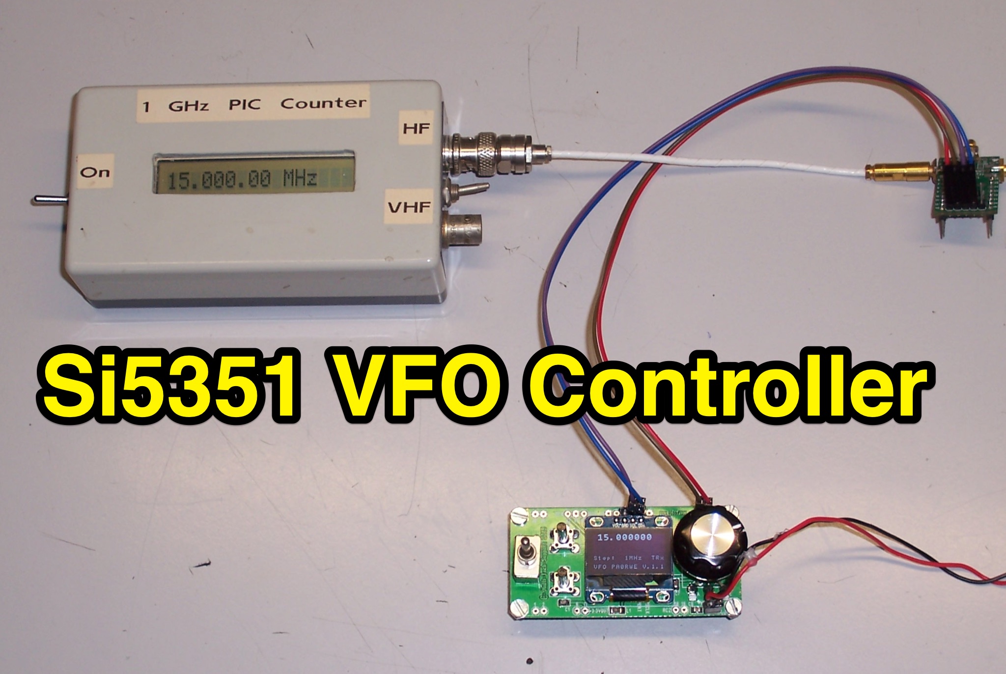 Learn how to build a VFO controller based on the Si5351 for ham radio operators. This controller consists of a PIC16F1825 and OLED SSD1306 display, with clock outputs for Tx, Rx, and IF frequencies. Features include calibration, RIT function, and the ability to tune frequencies separately. With step-by-step instructions and schematics, you can easily create your own VFO controller for your amateur radio setup.
 -
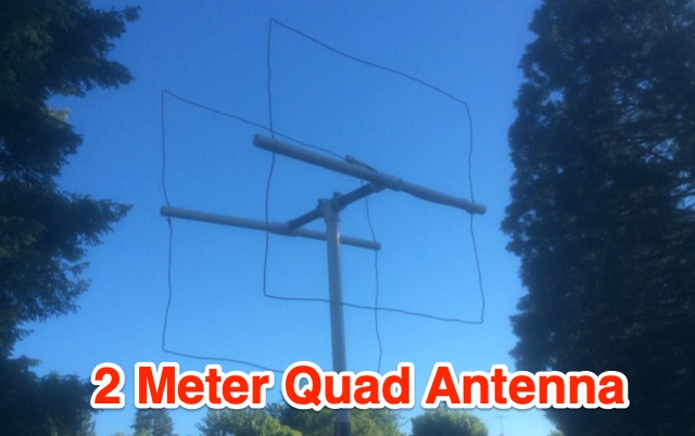 A detailed guide presents a simple 2-element quad antenna for 2m, offering ease of construction, portability, and efficient performance across the 144-148 MHz band. The design allows quick disassembly for storage and features adjustable polarization, making it ideal for various applications, including transmitter hunting and SSB operations.
 -
 Improve the FRG-7 operation adding a home made digital frequency display. The author explains the challenges of using the analogue dial on the FRG-7 and how a digital display can be a useful solution. The page provides detailed information about the FRG-7's design and frequency conversion process. It also includes step-by-step instructions on how to connect an external frequency counter to display the kHz part of the frequency.
 -
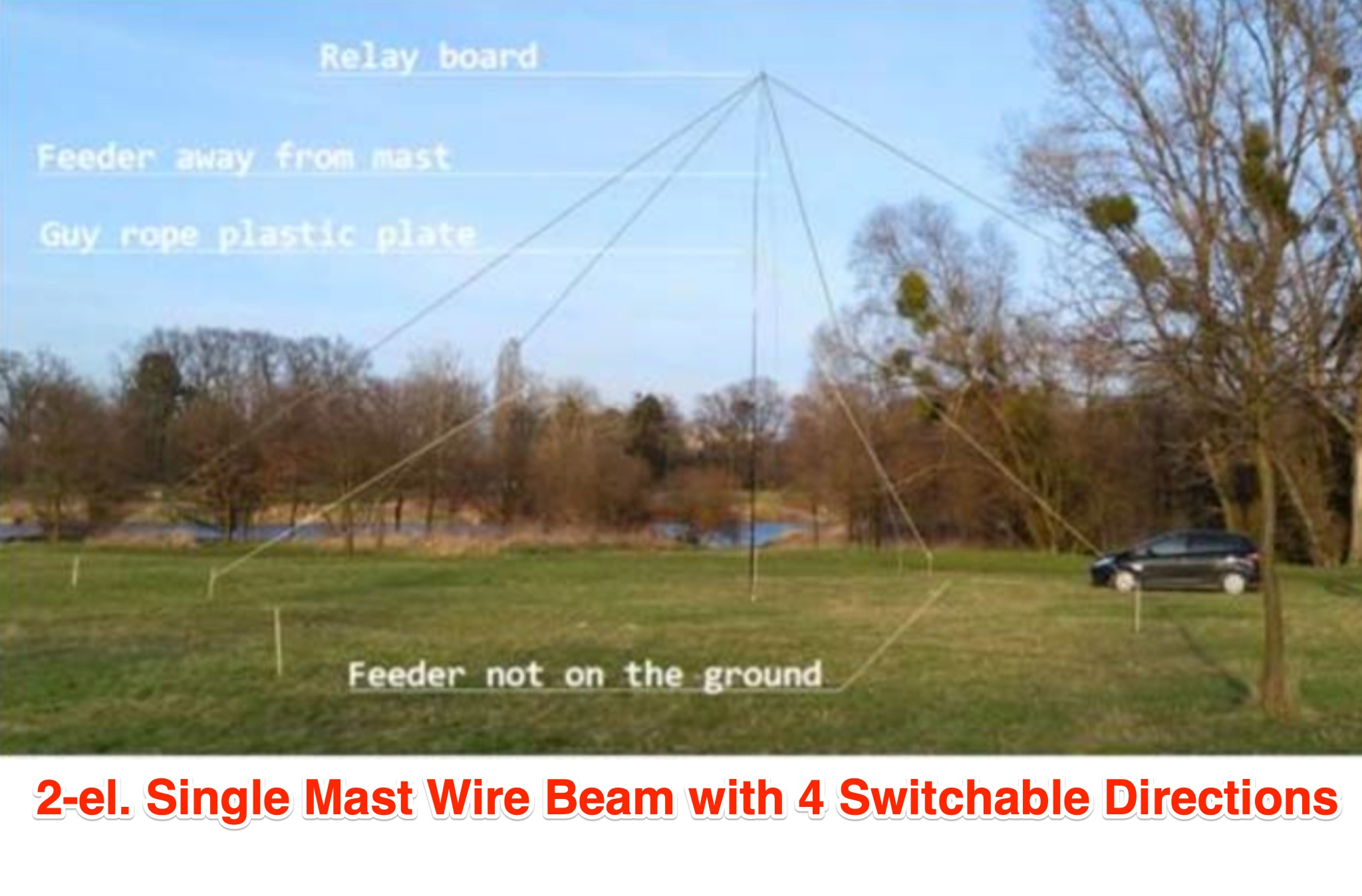 This article discusses the design and implementation of a 2-element wire beam antenna for the 20 meter band, suitable for field day operations with 4 Switchable Directions. The antenna is configured with sloped wires in an inverted V shape, with a specific design to achieve directional properties. The author tested the antenna design using MMANA and NEC2 software, based on a solution published in QST. Detailed diagrams and instructions are provided for constructing the antenna on top of a 12 meter mast, with specific wire lengths and positioning to ensure optimal performance. This resource is valuable for hams looking to build a directional antenna for the 20m band and improve their field day setup.
 -
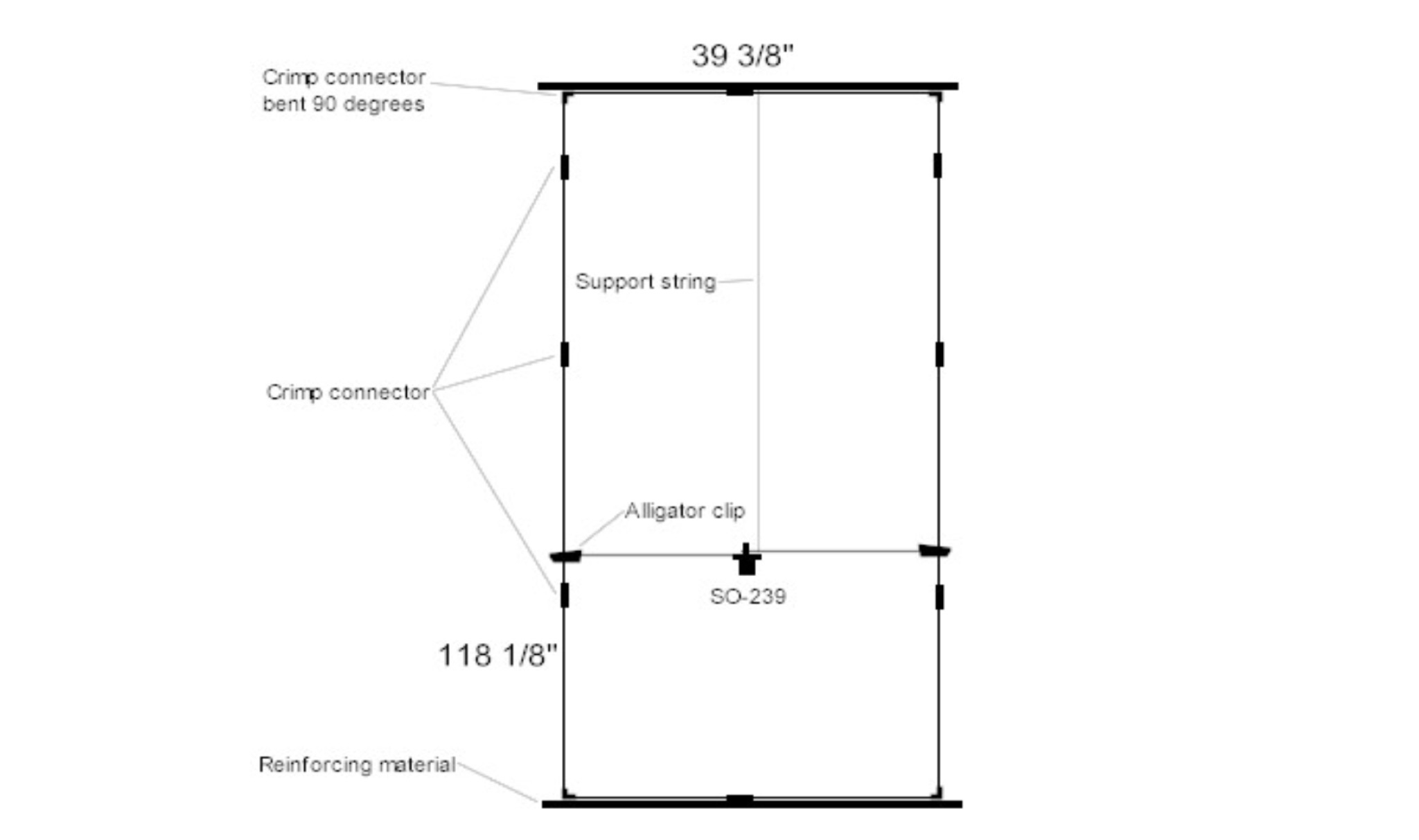 The K5USS 6 Meter Hentenna Project page on Hamuniverse provides detailed instructions on how to build a 6 meter directional antenna with 3.5 dBd gain. The project is presented with permission from K5USS, Charlie of Richardson, Texas. This directional antenna is a full wave loop on 6 meters, horizontally polarized but mounted vertically, with a 50 ohm impedance, ideal for 6 meter SSB operations. The page is useful for hams looking to construct their own directional antenna for improved performance on the 6 meter band.
 -
 Discover the secrets of Six Meters with this comprehensive eBook by Jim Wilson, K5ND. Learn about the magic of 6-meter DXing, including propagation, antennas, equipment, operating software, and more. Whether you're a beginner or an experienced ham radio operator, this book covers everything you need to know. With over 8,000 downloads, this updated version includes new chapters on FT8/FT4, MSK144, and Q65 modes, as well as contesting, rover operation, and awards. Get your hands on this valuable resource and enhance your 6-meter DXing experience today.
 -
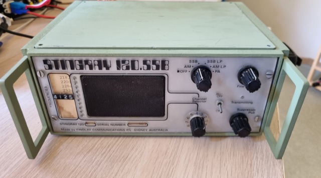 Recently, at the Ballarat Hamfest, the author acquired an old Marine transceiver for just $10, charmed by its sturdy construction and waterproofing. Made by Findlay Communications in Sydney, this crystal-controlled transceiver had been dormant but was reinvigorated with minor fixes. A manual was sourced, and further repairs were made, including an ingenious crystal oscillator replacement using an Si5351a controlled by an Arduino. The refurbished radio, complete with a fresh coat of paint and added customizations, is now operational for 160m AM and 30m SSB. A successful and cost-effective restoration.
 -
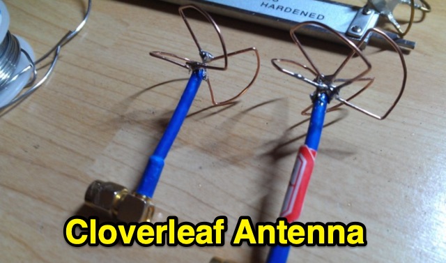 Cloverleaf antenna is a circular polarized antenna which is way better than the cheap dipole antenna that comes with video transmitters and receivers. The Cloverleaf is a closed loop antenna which the signal and ground wires are connected. The cloverleaf antenna has 3 loops at 120 degree apart, and they are titled at 45 degree to horizontal plane.
 -
 The Big Gun's Guide" is a comprehensive exploration of low-band propagation, aimed at serious Amateur Radio operators. It delves into the complex physics of the ionosphere at lower frequencies, contrasting it with HF propagation. The book covers essential topics like ionospheric fundamentals, propagation mechanisms, magneto-ionic effects, and disturbances. It also addresses the challenges of low-band DXing and provides insights for overcoming them. Brown's work is detailed and technical, offering valuable knowledge for those seeking to master the intricacies of low-band communication
 -
 VE1ZAC's analysis details the performance of **MFJ927** and **SGC239** autotuners with portable HF vertical antennas, specifically comparing 31 ft and 43 ft configurations. The resource originated from challenges encountered during a Maritime QSO Party roving operation, necessitating a lightweight and easily deployable antenna system. Target bands for the contest included 80, 40, 20, 15, and 10 meters, with a maximum power handling of 100 W CW. The author utilized a 30-foot carbon fiber push-up pole to support a vertical wire element, noting its 2 lb weight and reliability. EZNEC modeling was employed to predict performance, showing favorable results for a 30-foot vertical with elevated radials, particularly on 40 and 20 meters. Feedpoint impedance measurements, taken with an AIM4170C, are presented for various HF bands, both with and without a 41-foot RG6 stub designed to reduce reactance on 80 and 20 meters. The stub significantly improved matching on these bands, easing the tuner's workload. Operational tests revealed issues with the MFJ927's reliability during contest setup, leading to reliance on the K3's internal tuner. The SGC239, tested post-contest, performed flawlessly. A detailed side-by-side comparison covers mechanical aspects, connection options, power bias, impedance range, board quality, and documentation. Modifications to the MFJ927, including a new aluminum case, white paint for heat reduction, and upgraded impedance-measuring resistors, are also described.
 -
 The 2m 7 element Yagi antenna is a perfect beam antenna with 11dB gain and a front-to-back ratio of 20-25 dB. It has seven elements and requires a matching network built of 3/8" aluminum tubing and RG-8 cable. The gamma tube is adjusted to provide the best fit, and the gamma-driven element feeding clamp is tightened. If the beam is vertical, a non-conducting mast is utilized to prevent detuning and skewing of the radiation pattern. For optimal VHF operating, the antenna is installed at a height of 30 feet or higher.
 -
 Effective suppression of harmonics and parasitic radiation from HF transmitters is crucial, especially with the increasing sensitivity of VHF/UHF radio channels to interference. This project details a hybrid low-pass filter (LPF) designed to operate across the HF bands up to 51 MHz, making it suitable for 6-meter band operations while providing deep VHF/UHF suppression. The design addresses the challenge of modern interference landscapes, where even microvolt-level signals can disrupt wireless sensors and other simple VHF/UHF receivers. The filter utilizes a single elliptic link, combining high cutoff steepness with robust suppression in the hundreds of megahertz range. A key feature is the use of only two standard capacitor values, simplifying construction and component sourcing. The article provides a detailed schematic, performance characteristics, and _RFSim99_ model file, demonstrating a reflection coefficient S11 below 0.017 (VSWR < 1.03) across 1-51 MHz, ensuring minimal degradation to the antenna system. Construction notes include coil winding specifications and capacitor selection guidance, with recommendations for _FR-4_ assembly. Two capacitor sets are presented, with the first variant recommended for its lower RF current demands, keeping currents below 3 A at 1 kW passing power at 51 MHz. Fine-tuning involves adjusting frameless coils, with considerations for capacitor tolerance and high-frequency capacitance measurement accuracy.
 -
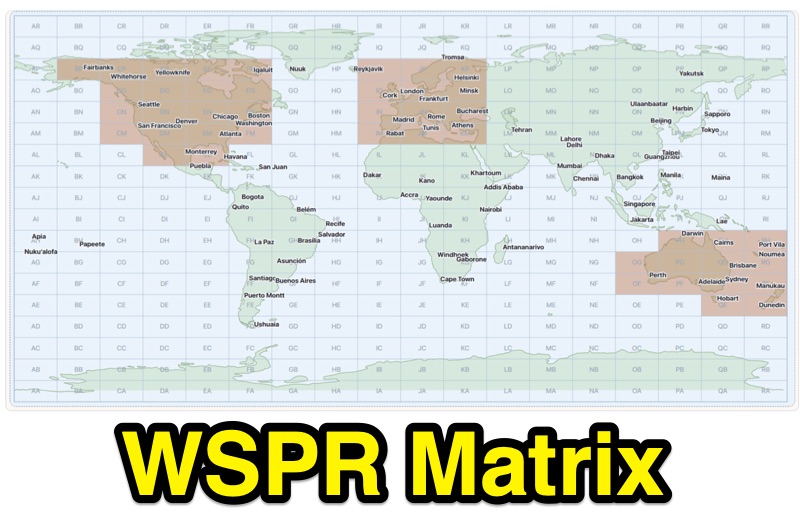 Demonstrates WSPR propagation activity, presenting observed data by reporter, band, UTC time, local time, and user-selected global destination areas. The application allows users to analyze WSPR spots from a live data server or import saved WSPRnet query files, bypassing the 10,000-row download limit by collecting individual band files for busy bands. Users can configure band preferences and destination modes, choosing between city radius or Maidenhead map grids for filtering path destinations. The interface provides options to start current-day live collection, a 7-day continuous archive, or load previously saved data to build the propagation matrix. Diagnostic information and archive history are accessible, alongside map setup controls for grid contrast and visibility. The tool supports both Path 1 and Path 2 map destinations, enabling detailed analysis of WSPR signal paths.
 -
 Understanding how radio frequency interference (RFI) is coupled into equipment and subsequently detected is crucial for amateur radio operators. This guide delves into the fundamental mechanisms of RFI, particularly focusing on detection at semiconductor junctions and the unintended antenna action of system wiring. It explains that most RFI detection follows a square law, meaning a 6 dB reduction in RF signal can result in a 12 dB drop in detected audio, offering a practical approach to mitigation. The resource also clarifies the concept of common mode versus differential mode signals, detailing how cable imperfections can convert common mode antenna current into differential signals. It addresses the critical "Pin 1 Problem" in audio interfacing, a common design flaw where cable shields connect to the circuit board instead of the shielding enclosure, leading to significant RFI issues. Practical solutions, such as proper shielding, using twisted-pair cables, and strategic bonding of equipment, are discussed to effectively reduce or eliminate RFI. The guide emphasizes the importance of proper filtering and the often-misunderstood concept of "ground" in electrical systems, distinguishing between earth ground, equipment ground, and circuit common. It provides insights into minimizing loop area in wiring to reduce inductively coupled noise and antenna action, drawing on the author's extensive engineering background and ham radio experience.
 -
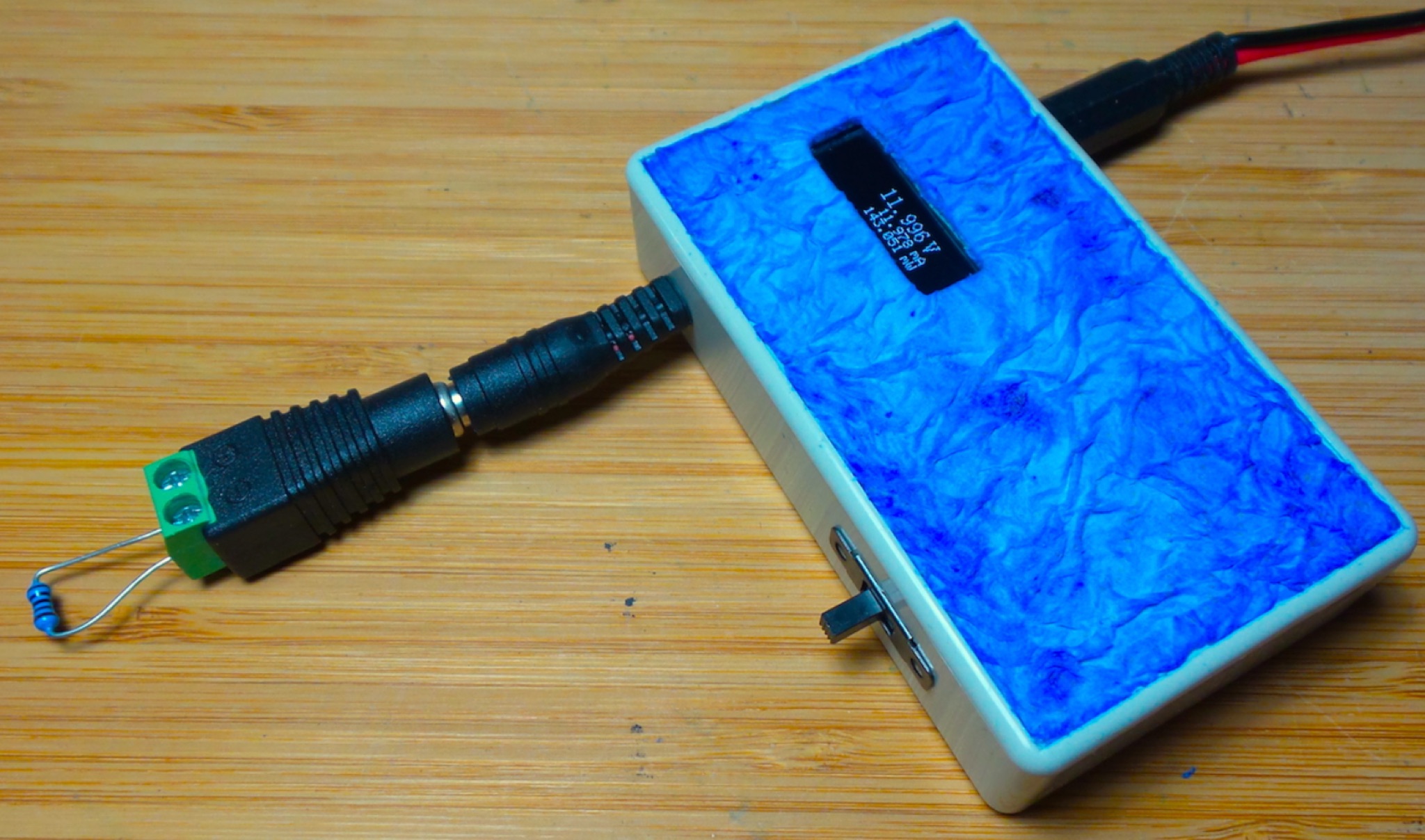 The DIY Power Meter project utilizes the _INA226_ high-side power monitoring chip, paired with an ATtiny85 microcontroller, to measure voltage, current, and power, displaying the results on a 128x32 OLED screen. The INA226 communicates via an I2C interface and is programmed with a calibration factor based on the shunt resistance and current register LSB. The project is designed to handle a maximum current of 500mA using a 0.16ohm shunt resistor, which can be adjusted to a 0.2ohm resistor, reducing the full-scale current range to 409mA with a resolution of **12.5uA**. The shunt resistor dissipates only 33mW at maximum current, making 1/4 watt resistors suitable for the setup. The PowerMeter.ino sketch configures the shunt resistance and maximum design current, automatically calculating the calibration factor. The project can be prototyped on a breadboard using an Arduino Uno, employing the Wire library for INA226 and OLED communication, and the u8g2lib library for the OLED display. For the ATtiny85 version, the Adafruit-TinyWireM and Tiny4kOLED libraries are used. The power meter is independently powered by a 3V CR2032 cell, with power switching options including manual switches or DC switched jacks. The low-side n-channel MOSFET switch configuration is tested but introduces voltage drop issues, making manual switching a more reliable option until a suitable DC switched jack is found. DXZone Technical Profile: INA226 | ATtiny85 | OLED Display | Power Meter
 -
 This report details a modification of a Diamond V2000 antenna, replacing its original two 0.50 m radials with two 1.55 m radials. Initial M5-threaded rods failed to fit; the housing required M6 threads. Custom radials were made using 8 mm OD aluminium tubing and M6-threaded stainless steel ends, secured with nuts machined to 9 mm. SWR issues on 6 m (>2:1) were largely due to a poor counterpoise connection, resolved during reassembly. NanoVNA measurements showed no adverse effects on 2 m or 70 cm. The final setup retains the two 1.55 m radials and original counterpoise. Other operators reported SWR degradation with similar mods—sometimes fixed by adding capacitance—but this was not observed here.
 -
 SZ1A's ongoing improvements are bolstered by donations, sponsorships, and volunteer work. Contributing to this collective effort, specialized lightning protection equipment, including ABB’s three-phase lightning arrestor and Crystal Audio's surge protection sockets, was installed. These enhancements safeguard sensitive electronics and reduce RF interference, highlighting the importance of community support in achieving the station's goals.
 -
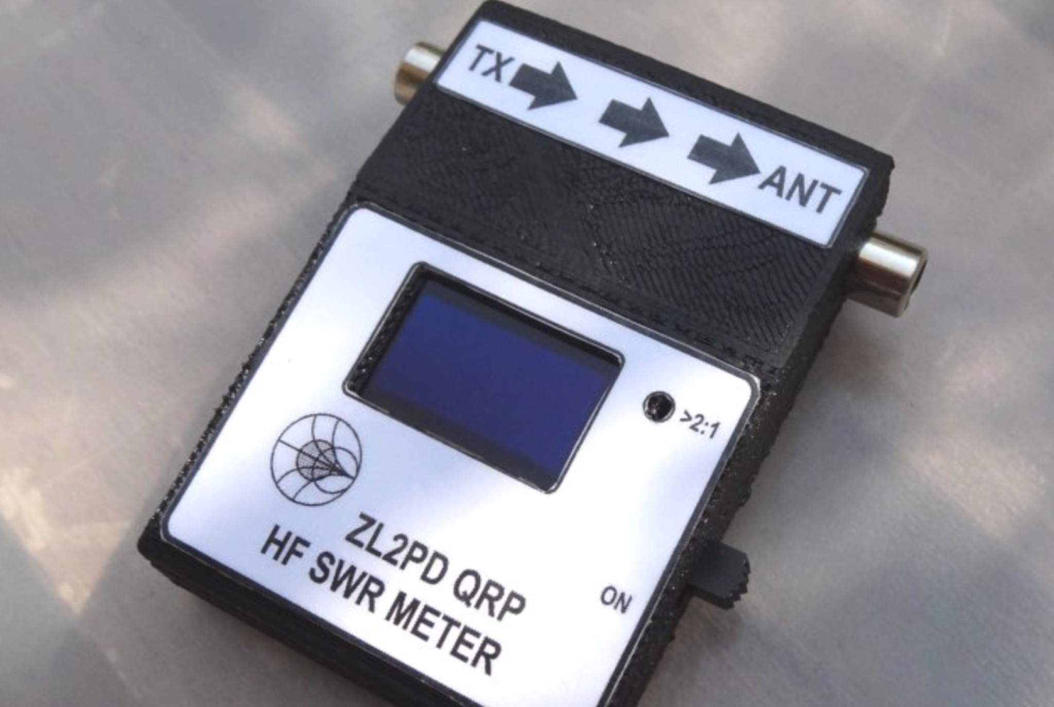 This project presents a compact QRP SWR meter featuring a 0.96" OLED display (128x64 pixels) for high-contrast visibility, updated with software fixes for display compatibility, improved low-power performance, and support for ATtiny45/85 microprocessors. A 1.3" OLED version accommodates visibility needs. Designed for HF QRP transmitters (3-15W), it uses a Breune coupler with germanium diodes for accurate SWR measurement. Powered by a AAA battery, the meter offers a standalone solution for impedance matching, with a 3D-printed enclosure enhancing portability.
 -
 The UV-K5 HF Fullband receive firmware version 0.3 introduces enhanced SSB capabilities using the SI4732-A10 chip. Released separately from UV-K5 CEC firmware, it offers improved HF reception, mode changes, frequency fine-tuning, and user modifications. New PCB designs and detailed usage instructions are included.
 -
 The Beam project offers various features for controlling antenna rotators, including support for 2 or 4 line LCD displays, software or hardware clocks, open collector drives for azimuth and elevation control, and internal calculations for tracking the sun and moon. It can also track satellites and supports "Flip Mode" for inverted antennas. The 4-line version provides detailed readouts while the 2-line version offers a more compact display. New versions now support PWM and I2C H-bridge modes for adjustable speed control at the end of a move.
 -
 This article demonstrates how to convert an existing tower into a dual-band vertical antenna for 80- and 160-meter DX operation. Using EZNEC modeling and practical design principles, the authors achieved a low-profile, efficient setup with a single coax feed line, no moving parts, and optimal radiation patterns. The system integrates an 80-meter vertical wire and a 160-meter shunt-fed gamma match for simultaneous operation. Detailed construction insights, including feed system and capacitor configurations, offer a reliable, full-legal-power solution.
 -
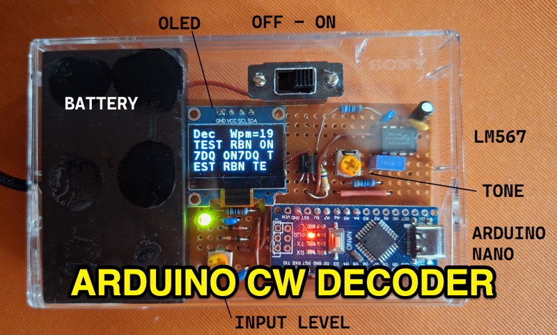 The project details the construction of a small, portable **CW decoder** built around an Arduino Nano and an LM567 tone decoder circuit. It integrates an OLED display for output and is powered by a 1200 mAh Li-Po battery. The Arduino Nano is programmed with a modified version of the OST Morse Box firmware, originally based on Budd, WB7FHC's work, provided as a HEX file for flashing. The LM567 output connects to Arduino pin D2, while pins A6 and A7 are grounded due to the absence of potentiometers, simplifying the circuit. Standard I2C connections are used for the OLED: SDA to A4 and SCL to A5. The entire assembly, including the Arduino, OLED, and decoder circuit, is mounted on a perfboard to fit precisely within an old cassette tape box. This design emphasizes portability and compact form factor. Parameters for the decoder can be adjusted using a dedicated Windows Control program, offering flexibility in operation. The resource provides practical insights into adapting existing firmware for specific hardware constraints and achieving a self-contained, battery-powered **Morse code** decoding solution.
 -
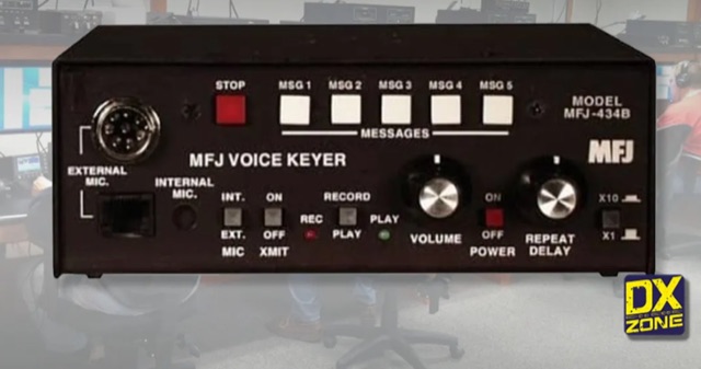 Let this microprocessor controlled MFJ Contest Voice KeyerTM call CQ, send your call and do contest exchanges for you in your own natural voice
 -
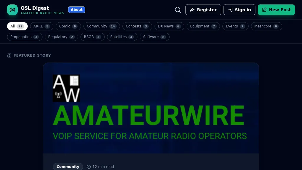 QSL Digest presents a curated collection of daily news and commentary relevant to the amateur radio community, drawing content from various sources. The platform features articles on diverse subjects such as **contesting**, new equipment releases, and current propagation conditions, alongside updates on satellite operations and the activities of prominent amateur radio operators. It functions as a community-driven hub, aggregating information to keep hams informed about developments across the hobby. The site distinguishes itself by offering special features and a regular comic, adding unique elements to its news delivery. Content is sourced from the community itself, fostering a collaborative environment for information sharing. Each entry provides a concise summary and a direct link to the original source, allowing readers to quickly access detailed articles and stay current with the latest happenings in the amateur radio world.
 -
 Demonstrates the construction of an active loop converter specifically designed for the Low Frequency (LF) bands, addressing common localized noise interference in LF reception. The design integrates a sharply tuned circuit and a tuned loop antenna, utilizing the loop as the sole tuned inductive element. By applying positive feedback, the converter significantly increases the loop's effective Q, achieving factors between 1000 and 2000, which sharpens tuning and reduces noise. The circuit employs an _NE602_ mixer stage, feeding its output to an HF receiver, with a crystal-locked local oscillator at 4 MHz. A 20-turn, 0.8-meter square loop antenna with 500 uH inductance is detailed, connected via 2 meters of figure 8 flex cable. The converter offers three selectable frequency bands: 195-490 kHz, 150-220 kHz (including the New Zealand amateur band), and 128-160 kHz (covering the European amateur band). Performance measurements indicate an effective 3dB bandwidth of approximately 100 to 200 hertz at 200 kHz. The article provides insights into component selection, including an _LF353_ op-amp and a trifilar wound transformer on a ferrite core. Sensitivity figures are presented, showing 7.5 uV of converted output per 1 uV/meter signal strength into a 50-ohm load, or 37.5 uV into an _FRG7_ receiver, highlighting its capability to extract weak signals from noise.
 -
 Presents DJ5IL's personal amateur radio station, detailing his journey as a licensed operator since 1973. The resource covers his **shack setup**, including an Elecraft K4D, Icom IC-7610, and various vintage transceivers like the Drake 2-B, along with a SPE Expert 1K-FA amplifier. Antenna systems include a PRO.SIS.TEL RD1524T rotary dipole for 40/20/15/10m at 15m height, an 18m vertical dipole with an SGC SG-230 tuner for 3.5-30 MHz, and an inverted-V dipole for 80m. The site features a **QSL gallery** showcasing his custom card designs and outlines his QSL policy, emphasizing the exchange of unique, personalized cards over generic confirmations. It also includes a detailed operator's biography, tracing his early fascination with radio, obtaining his license at 16, and memorable QSOs, such as a contact with his blood-relative W3NZ. The resource also delves into the historical significance of amateur radio's role in pioneering shortwave communication following the 1912 International Radiotelegraph Convention, which initially relegated amateurs to wavelengths of 200 meters and shorter. DJ5IL's philosophy on "ham spirit" is discussed, stressing the unpolitical nature of amateur radio as a global fraternity.
 -
 This page provides a detailed review and installation experience of a new 6 and 2 meter dual band Yagi antenna. The author shares insights on the purchase process, shipping, assembly, and performance of the antenna in their backyard setup. The content is useful for hams looking for information on dual band Yagi antennas, especially those interested in improving their contest operations or backyard installations. The author's personal experience and challenges with mounting the antenna on a small push-up mast are also discussed.
 -
 This article discusses the evolution of portable amateur radio operations, focusing on optimizing backpack-carried equipment for outdoor use. The author shares his journey from using wheeled carts to developing an innovative backpack-mounted antenna system, emphasizing the transition from high-power (QRO) to low-power (QRP) operations to reduce weight. The piece details practical solutions for antenna mounting, equipment selection, and portable operations in challenging terrain, particularly along Ontario's Niagara Escarpment. The author's approach prioritizes mobility and functionality while maintaining effective radio communications in remote locations.
 -
 Operating on the 60m band requires specialized antennas, and the 2 Element HB9CV, also known as the _ZL special_, excels in this domain. With a gain of **7.3 dBi** when phased at a 162-degree shift, it rivals traditional 3-element Yagi antennas, making it a solid option for enhancing 60m operations. The construction process is thoroughly detailed, providing insights into its performance and practical applications. Real-world comparisons demonstrate that the HB9CV antenna outperforms long Beverage antennas by an average of **5.5 dB** in reception, showcasing its effectiveness in various conditions. Insights from Mr. Cebik's analysis further validate its design, confirming its capability to maximize communication on the 60m band.