Search results
Query: 15 m wire antenna
Links: 65 | Categories: 0
-
 How to build Fan-Dipoles by DK7ZB. Experiences with various band combinations. Not all combinations are working properly. If the frequencies are to close together the impedances will lead to a very bad SWR. This happens with the bands 10-12-15m or 15-17-20m.
 -
 A light and sturdy Quad for 10 and 15 meters. Basic Quad antenna design considerations. Building and assembling a dual band HF QUAD antenna, designing and joining cross-arms and boom, assembling spreader and element wire installation notes. QST article.
 -
 This is a standard calculation method that can help you while tuning dipole antennas, by adjusting wire lengths. This method can be used also when you need to add lenght to your wires, and can be additionally used to quarter waves vertical antennas
 -
 I used a FT 240-43 for much more power, not needed but beter safe than sorry. 150 Watt continious, 300 Watt PEP SSB, 90 Watt Digimodes 10 Mhz, 18 Mhz, 24 Mhz Very easy to build design and a good antenna for people who don't have much space for big towers or long wires This design is from Hans - PE1RNU
 -
 Building A Full-Wave Quad Loop Antenna for 6 Meters. This is an easy antenna to build and the materials cost about $15-20. It exhibits 1.8dB gain over a 1/2-wave dipole. Using an open-wire parallel feedline (commonly called ladder line) with an antenna tuner, it tunes up on the 10m band as a 5/8-wave loop as well
 -
 A 60-foot available space, for example, might necessitate a shortened multiband dipole array to cover 80, 40, and 15 meters effectively. This resource details the construction of such an antenna, combining full-size and coil-loaded dipoles on a single feedline. It addresses the common challenge of fitting multiple HF bands into restricted physical footprints, providing practical guidance for hams with smaller backyards or portable operations. The core of the offering is an interactive calculator that determines required loading coil inductance and dipole lengths for various amateur bands from 160m to 10m. Users input their available space, and the tool provides dimensions, coil turns, and an efficiency rating (Good or Fair) based on the antenna's electrical length relative to a quarter-wavelength. It also suggests suitable _PVC_ pipe diameters for coil forms. The article further illustrates a center feed-point assembly using an 18-inch section of 2-inch _PVC_ pipe, detailing eye-bolt spacing and coaxial connector installation. It emphasizes the importance of adequate spacing between parallel dipoles and offers customization options for the feed-point, including the addition of a _Balun_ for improved feedline isolation.
 -
 Vertical end fed antenna used for portable operations. The antenna will work on 80 with acceptable results, it will work fine on 40m, and it will be a good deal better than a normal 1/4 wave GP on 20, 17, 15 meters.
 -
 Building an End-Fed Half-Wave (EFHW) antenna from a kit, as detailed by Frank Bontenbal, PA2DKW, with process photos by Bob Inderbitzen, NQ1R, offers a practical approach for hams. This specific kit, a collaboration between ARRL and HF Kits, targets 10, 15, 20, and 40 meters, making it a versatile option for HF operations. Unlike a center-fed dipole, the EFHW is a half-wavelength antenna fed at one end, which simplifies deployment, particularly for portable use. The construction guide meticulously outlines the assembly of the 49:1 impedance matching network, crucial for transforming the antenna's high impedance (around 2,500 Ohms) to a transceiver-friendly 50 Ohms. Steps include preparing the enclosure by drilling holes for the coaxial connector and antenna connections, followed by the precise winding of enameled copper wire onto a toroid to create the transformer. The guide emphasizes careful insulation removal and soldering for reliable connections. Final assembly involves integrating a 100 pF capacitor for higher band compensation, soldering the transformer's primary and secondary sides, and conducting SWR tests with a 2K7 resistor or a half-wavelength wire. The document also provides examples of wire lengths for different bands, such as 16 feet for 10 meters or 66 feet for 40 meters, demonstrating the transformer's adaptability for various half-wavelength configurations.
 -
 How to Design and Build a Field Expedient End-Fed Half-Wave Antenna for 20m, 40m and 80m. This Shorty 80m EFHW comprises a 49:1 autotransformer (to match the very high impedance at the end of a half-wave wire), a half-wavelength wire for 40m (also a quarter-wavelength for 80m), a loading coil and a short tail wire. The coil and the short tail wire (about 6 feet) make up the other quarter wave on 80m.
 -
 The U01 emergency communications antenna is a versatile, multiband antenna designed for 80/60/40/20/17/15/10m bands, known for its reliability and compact size. It features a broadband transformer wound on various core options like FT82-43, FT114-43, or FT140-43, with the latter capable of handling up to 100W. The antenna incorporates a PCB with options for SMA and BNC connectors, and a weather-proofed design for durability. The lightweight construction, using materials like DX Wire UL and Polyester rope, makes it highly portable. The antenna's design has been tested and proven within the DARC Chapter U01, with multiple build options and detailed documentation available for DIY enthusiasts.
 -
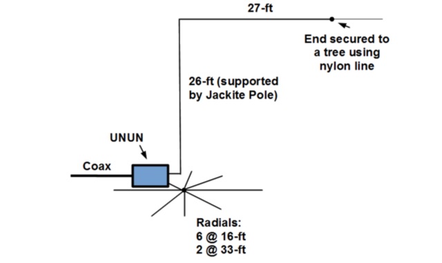 Inverted L antenna, even if not completely freestanding, it only requires one line to be lauched into a tree to support the end of the horizontal wire. This project is done with a 31-foot Jackite pole for a support and uses six 15-foot radials and one 33-foot radial.
 -
 The Portable EFHW antenna for the 40, 20, 15, and 10-meter bands utilizes a broadband transformer with a 1:49 ratio, designed on a PCB by either Jan or DL2MAN. The design incorporates an **FT114 core**, offering an alternative to the FT82 core. The antenna requires precisely 20.5 meters of DX Wire Ultralight for optimal performance. Additional components include DX Wires "Dyneema" 1mm rope and 1mm bricklayers string for structural support. The SWR plot indicates performance at two elevation heights: 5.5 meters (blue line) and 4 meters (yellow line), demonstrating optimization for low-elevation portable use without poles. The antenna's components, including spool and rope tensioners, are available for 3D printing, with spool dimensions scaled to 130% for a length of approximately 110mm. The design emphasizes simplicity and portability, suitable for field deployment.
 -
 The tri-band trapped delta loop antenna design operates on 80 meters (3.5–4 MHz), 40 meters (7–7.3 MHz), and 30 meters (10.1–10.15 MHz) using a single triangular wire loop. This configuration eliminates the need for an external antenna tuner or band-switching relays. The antenna's physical perimeter, approximately 270 feet, establishes 80M as the fundamental band, with specific trap placements enabling resonance on 40M and 30M. Trap design and placement are critical, with 30M traps positioned inboard of 40M traps within the horizontal element. Each slant leg measures approximately 80 feet. The resource references foundational information from the _ARRL Antenna Handbook_ and _ON4UN’s Low Band DXing_ regarding full-wave loop behavior and feedpoint impedances. The project aims to provide multi-band HF operation from a single, fixed antenna structure.
 -
 This project outlines a simple, cost-effective 40m band HF dipole antenna design, ideal for beginners. Constructed with insulated copper wire and a 1:1 balun, it offers a 50-ohm impedance, suitable for both 40m and 15m bands due to the harmonic relationship. Calculations account for a K factor, ensuring optimal length and performance. Antenna modeling with 4NEC2 confirms practical access to both bands, though real-world results may vary. Lightweight materials and straightforward assembly make it an accessible and versatile amateur radio solution.
 -
 VE1ZAC's analysis details the performance of **MFJ927** and **SGC239** autotuners with portable HF vertical antennas, specifically comparing 31 ft and 43 ft configurations. The resource originated from challenges encountered during a Maritime QSO Party roving operation, necessitating a lightweight and easily deployable antenna system. Target bands for the contest included 80, 40, 20, 15, and 10 meters, with a maximum power handling of 100 W CW. The author utilized a 30-foot carbon fiber push-up pole to support a vertical wire element, noting its 2 lb weight and reliability. EZNEC modeling was employed to predict performance, showing favorable results for a 30-foot vertical with elevated radials, particularly on 40 and 20 meters. Feedpoint impedance measurements, taken with an AIM4170C, are presented for various HF bands, both with and without a 41-foot RG6 stub designed to reduce reactance on 80 and 20 meters. The stub significantly improved matching on these bands, easing the tuner's workload. Operational tests revealed issues with the MFJ927's reliability during contest setup, leading to reliance on the K3's internal tuner. The SGC239, tested post-contest, performed flawlessly. A detailed side-by-side comparison covers mechanical aspects, connection options, power bias, impedance range, board quality, and documentation. Modifications to the MFJ927, including a new aluminum case, white paint for heat reduction, and upgraded impedance-measuring resistors, are also described.