Search results
Query: 20 10 dipole
Links: 79 | Categories: 0
-
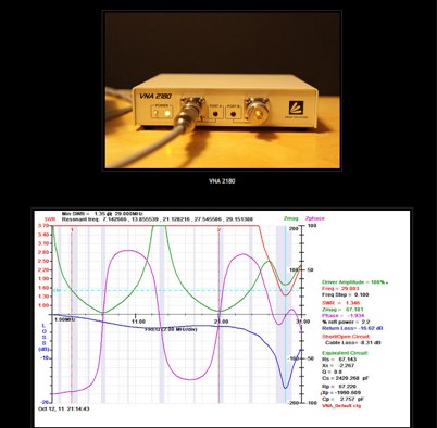
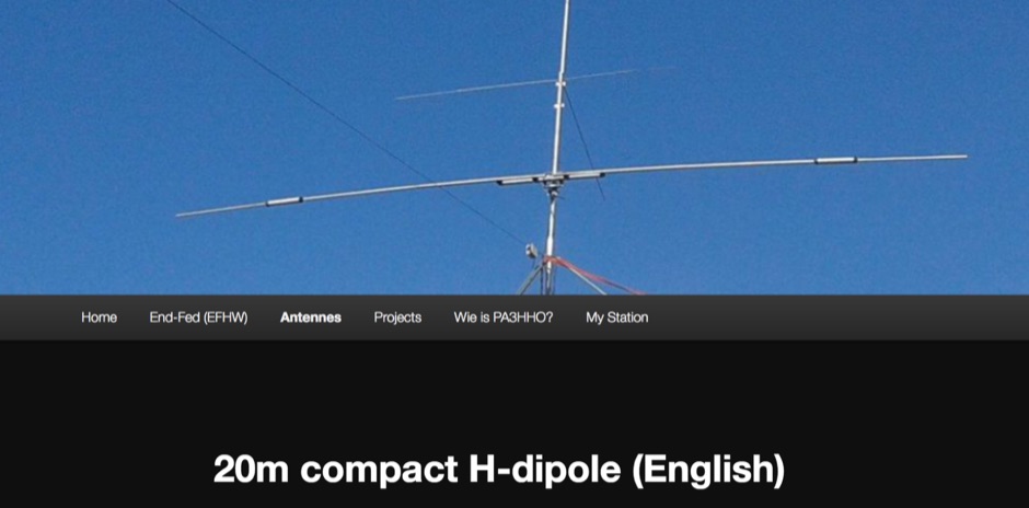 Only 2x 10ft wide, performance similar to full-size dipole, covers whole band with SWR better than 1:1.2.
 -
 A three band short Vee antenna is feasible with two legs per side on a dipole. 10-15-20 meters by W8HDU
 -
 A Co-ax Trap Dipole For 40, 30 and 20 Meters or at last that was the intention
 -
 The X80 multi-band HF vertical antenna, a commercial iteration of the Rybakov design, exhibits a physical length of 5.5 meters, or approximately 18 feet, and is constructed from aluminum tubing. It operates as a non-resonant vertical, requiring an external antenna tuner for impedance matching across its intended operating frequencies. The antenna's design incorporates a 1:4 UNUN at its base, facilitating a nominal 50-ohm feed point impedance for the coaxial cable. Performance observations indicate effective operation on 40 meters, 20 meters, 15 meters, and 10 meters, with reduced efficiency on 80 meters and 160 meters due to its relatively short electrical length for these lower bands. Comparative analysis with a G5RV dipole and a half-wave end-fed antenna reveals the X80 offers a lower take-off angle, beneficial for DX contacts, particularly on the higher HF bands. Field tests conducted with an Icom IC-706MKIIG transceiver and an LDG AT-100ProII autotuner demonstrate the X80's ability to achieve acceptable SWR across 80m through 10m. The antenna's compact footprint and ease of deployment make it suitable for restricted spaces or portable operations, though its performance on 80 meters is noted as a compromise compared to full-size resonant antennas.
 -
 A post about the construction and measurements of a Resonant Feedline Dipole cut for the 10M band
 -
 Based on a simple project based on a 2 elements Yagi for 20m band, and then becomed a triband yagi with a open-sleeve feed system
 -
 This article describes the design and simulation of a multiple dipole antenna for the HF band, using the software MMANA-GAL. The antenna will be designed to operate in the 10, 20, 40 and 80 m bands
 -
 Experimenting vertical wire antennas for 40 and 20 meters supported by balloons resulting in excellent gain in RX and good overall performance against horizontal dipole
 -
 How to build Fan-Dipoles by DK7ZB. Experiences with various band combinations. Not all combinations are working properly. If the frequencies are to close together the impedances will lead to a very bad SWR. This happens with the bands 10-12-15m or 15-17-20m.
 -
 The antenna in this project is a modification of the techniques used to design a multiband fan type dipole with little or no tuning involved having a total space of 105 feet
 -
 A Six-element Yagi Beam for 6 Meter by W1JR proiddes a power gain of 10.2 dB over a dipole it is built on a 24 foot long boom
 -
 An inverted V Dipole antenna for HF bands, working on 10 20 40 and 80 meters band. PDF Presentation
 -
 An experimental prototype of an asymmetrical hatted vertical dipole antenna that can work on HF bands 20 to 10 meters band. The AHVD Vertical dipole is an upside-down T design
 -
 The OCFD Off-Center-Fed Dipole Antenna is an excellent multiband antenna that is relatively simple to construct, yet gets quite decent performance.
 -
 A multi-band off centre fed dipole, designed to operate on all bands from 40m (7MHz) to 6m (50MHz). Author claims it will operate on 40, 30, 20, 17, 15, 12 and 10m without an ATU (SWR <3:1) plus 6m with an ATU.
 -
 The ZS1J/B beacon operates on 28.2025 MHz with 5 Watts output to a half-wave, end-fed vertical antenna, initially installed in 1977 as ZS5VHF near Durban. The 10-meter transmitter is a modified 23-channel CB radio, and the identification keyer uses a diode matrix unit with TTL ICs from the same era. After relocation to Plettenberg Bay in 1993, the beacon has been in continuous service, with additional QRP transmitters later installed for other bands. In 1994, a single-transistor, 80-meter, 0.5-watt QRP transmitter with a half-wave dipole was added on 3586 kHz, followed by a 160-meter, 0.5-watt unit on 1817 kHz. A 30-meter, 0.5-watt transmitter was installed in 1996, operating on 10.124 MHz. In 2002, a 40-meter QRRP beacon on 7029 kHz, with an output of 100 microwatts, achieved DX reports up to 1100 km from ZS6UT in Pretoria. Best DX reports for the 80m and 160m beacons came from 9J2BO.
 -
 The Tri-pole antenna, a clever modification of a standard dipole, allows for dual-band operation by integrating a third element. This design effectively shortens the overall dipole length by 10 to 20 percent, simplifying antenna rotation and offering a compact footprint. KK4OBI's article delves into the operational principles, using a 6 and 10-meter Tri-pole as a primary example, and provides comprehensive instructions for constructing any Tri-pole antenna within the 6 to 15-meter range. Key to the Tri-pole's performance is its off-center feed, necessitating a common mode choke at the feed point for optimal tuning and reduced noise. The author outlines a methodical approach to determining element dimensions, starting with a vertical element frequency calculated as 0.47 times the sum of the desired upper and lower band frequencies. This calculation, along with K-values derived from trend lines, guides the initial lengths for the horizontal arms, demonstrating how a 10m-6m Tri-pole can achieve a total horizontal length 78% shorter than a conventional 10-meter dipole. Tuning and balancing are critical, with the article detailing adjustments to arm lengths and the vertical element to achieve balanced SWR values, as validated through 4NEC2 simulations. Radiation patterns are analyzed at various elevations, showing gains around 5.7 dBi and favorable take-off angles for DX contacts. Construction details specify aluminum tubing dimensions, U-bolts, and an SO-239 connector, emphasizing the importance of a ferrite-based choke for wideband operation.
 -
 This type of antenna is a popular antenna design as the performance is very good across the HF bands and requires little or no tuning. It’s a dipole fed off center with a 4:1 balun at the offset feed point. The antenna shown covers 80, 40, 20 and 10 meters. The formula can also be used to adjust the overall length to cover more or fewer bands and the resulting overall length. 160-10m, 80-10m or 40-10 meters depending on your available space. Other bands will require a tuner.
 -
 This page delves into the Inverted V antenna, a source of myths among ham radio operators. The author explores the behavior of this antenna type with a focus on a 20m half-wave dipole positioned 10m above the ground. From Pythagoras to high school math, the article simplifies the calculation of dimensions and angles for setting up an Inverted V antenna. It includes a spreadsheet for calculating hypotenuse length and angles, crucial for antenna setup. Additionally, it provides insight into the radiation pattern of a 'flat' half-wave dipole at 10m height. Useful for hams planning to optimize their antenna setup. In Norwegian.
 -
 Building A Full-Wave Quad Loop Antenna for 6 Meters. This is an easy antenna to build and the materials cost about $15-20. It exhibits 1.8dB gain over a 1/2-wave dipole. Using an open-wire parallel feedline (commonly called ladder line) with an antenna tuner, it tunes up on the 10m band as a 5/8-wave loop as well
 -
 Operating as FY/F5UII, Christian F5UII conducted a DXpedition to French Guiana (FY) from January 13 to 30, 2013. The primary operation utilized the FY5KE radio club station in Kourou, with activity focused on voice modes during specific weekday hours. The resource details the operator's intent to transmit before 12:00z and after 22:00z, or as availability permitted, from the mainland. A significant aspect of this operation involved a dedicated weekend activation of the Salut Islands, specifically **IOTA SA-020**, from January 19-20, 2013. This segment of the DXpedition was conducted from Royal Island (Ile Royale), part of a group including Devil's Island (Ile du Diable) and St. Joseph Island (Ile Saint Joseph), located 14 km offshore from Kourou. The station setup for the IOTA activation included 100 Watts of power, a GPA-030 vertical antenna for 10m, 15m, and 20m, and dipole antennas for 17m and 40m, with antenna deployment contingent on site conditions and propagation. The operator anticipated strong interest for the SA-020 entity.
 -
 Building an End-Fed Half-Wave (EFHW) antenna from a kit, as detailed by Frank Bontenbal, PA2DKW, with process photos by Bob Inderbitzen, NQ1R, offers a practical approach for hams. This specific kit, a collaboration between ARRL and HF Kits, targets 10, 15, 20, and 40 meters, making it a versatile option for HF operations. Unlike a center-fed dipole, the EFHW is a half-wavelength antenna fed at one end, which simplifies deployment, particularly for portable use. The construction guide meticulously outlines the assembly of the 49:1 impedance matching network, crucial for transforming the antenna's high impedance (around 2,500 Ohms) to a transceiver-friendly 50 Ohms. Steps include preparing the enclosure by drilling holes for the coaxial connector and antenna connections, followed by the precise winding of enameled copper wire onto a toroid to create the transformer. The guide emphasizes careful insulation removal and soldering for reliable connections. Final assembly involves integrating a 100 pF capacitor for higher band compensation, soldering the transformer's primary and secondary sides, and conducting SWR tests with a 2K7 resistor or a half-wavelength wire. The document also provides examples of wire lengths for different bands, such as 16 feet for 10 meters or 66 feet for 40 meters, demonstrating the transformer's adaptability for various half-wavelength configurations.
 -
 This article discusses suitable first HF antenna options for amateur radio operators with limited space. It recommends an Off-Center Fed (OCF) Dipole and a Vertical Dipole, detailing the installation processes, considerations for stealth and ease of setup, and the characteristics that make them ideal for newcomers. Safety warnings and maintenance tips are provided to ensure effective and secure operation.
 -
 A coaxial cable trap is a fundamental component in multiband antenna design, enabling a single radiator to resonate efficiently on multiple frequencies by electrically shortening or lengthening the antenna element. This project focuses on constructing such a trap for a vertical antenna operating on the 10 MHz (30m) and 14 MHz (20m) amateur bands, providing practical insights into its fabrication and integration. The article outlines the specific dimensions and winding techniques for the coaxial trap, emphasizing the use of readily available materials. It details the physical construction of the vertical element, including the mast and radiating sections, to achieve optimal performance across both target bands. The author shares personal experiences with similar trap designs, noting their effectiveness in previous horizontal dipole configurations. Key construction steps are illustrated with _original photos_, showing the assembly of the trap and its incorporation into the overall antenna structure. The design aims for a compact footprint, making it suitable for limited space installations while still delivering effective DX capabilities on the **30-meter** and **20-meter** bands.
 -
 The article describes the construction of a 1:49 impedance transformer designed to match the high impedance (around 2500Ω) of an end-fed half-wave (EFHW) dipole antenna to the 50Ω impedance of a typical transceiver. The EFHW is a popular portable antenna due to its simple construction, but feeding it can be challenging compared to a center-fed dipole. The transformer was built using an FT240-43 ferrite toroid core, with 2 primary and 14 secondary windings for a 1:49 impedance ratio. A capacitor was added in series with the primary winding to improve performance at higher frequencies. The author compared versions with one and two cores, and found that 100pF worked best for the single core design while 200pF was optimal for the dual core transformer.
 -
 The article details the design and construction of a four-band Moxon beam by a radio amateur. The beam, mounted atop a rooftop tower, aimed for gain over a dipole on 20 meters, cost under $500, and included additional bands. The design features fiberglass spreaders, four bands (20/15/10/6 meters), and a single feedpoint. The construction involved computer modeling, NEC source code, and specific dimensions. The article outlines the assembly, materials, and tuning process, including in-situ adjustments for optimal performance. Despite initial challenges, the beam improved signal strength and facilitated contacts on multiple bands, marking it as the best HF antenna the author has owned.
 -
 From March 2 to March 11, 2018, a Norwegian team operated as Z2LA from Zimbabwe, focusing on 160m through 10m bands using SSB and CW modes. The operation, described as "holiday style," aimed to provide contacts for DXers worldwide seeking a rare DXCC entity. Key equipment included a SUNSDR PRO II, an Elecraft KX3, and an Icom 706 MK2G as a spare radio, supported by two Juma 1000 amplifiers for robust signal output across the bands. Antenna systems were tailored for multi-band operation, featuring an Inv L for 160m and 80m, sloping dipoles for 30m/40m, and a _Hexbeam_ from SP7IDX Technology covering 20m to 10m. For improved reception, the team deployed a SAL 30, two reversible BEV antennas from remoteqth.com, and a BOG from K1FZ, enhancing their ability to hear weak signals. QSL information directs operators to Clublog for log search and M0OXO Charles for OQRS, explicitly requesting no bureau cards. The team comprised LA7THA Rune, LA7WCA Arne, and LA9VPA Thor, successfully making numerous contacts and contributing to the DX community's pursuit of _Zimbabwe_ as a DXCC entity.
 -
 Presents DJ5IL's personal amateur radio station, detailing his journey as a licensed operator since 1973. The resource covers his **shack setup**, including an Elecraft K4D, Icom IC-7610, and various vintage transceivers like the Drake 2-B, along with a SPE Expert 1K-FA amplifier. Antenna systems include a PRO.SIS.TEL RD1524T rotary dipole for 40/20/15/10m at 15m height, an 18m vertical dipole with an SGC SG-230 tuner for 3.5-30 MHz, and an inverted-V dipole for 80m. The site features a **QSL gallery** showcasing his custom card designs and outlines his QSL policy, emphasizing the exchange of unique, personalized cards over generic confirmations. It also includes a detailed operator's biography, tracing his early fascination with radio, obtaining his license at 16, and memorable QSOs, such as a contact with his blood-relative W3NZ. The resource also delves into the historical significance of amateur radio's role in pioneering shortwave communication following the 1912 International Radiotelegraph Convention, which initially relegated amateurs to wavelengths of 200 meters and shorter. DJ5IL's philosophy on "ham spirit" is discussed, stressing the unpolitical nature of amateur radio as a global fraternity.
 -
 The TY0RU DXpedition to Benin in 2022 achieved over **100,000 QSOs** from Cotonou, IOTA AF-051, operating across 160m through 6m bands using CW, SSB, and FT8 modes. The operation involved a team of 12 operators, including _F5RAV_, _F4WBN_, and _F1TCV_, utilizing multiple stations with transceivers like the Icom IC-7300 and IC-7610, paired with amplifiers and various antennas such as verticals, dipoles, and a 4-square array for 40m. The expedition's log is available on Club Log, supporting OQRS for both direct and bureau QSLs, with F5RAV serving as the QSL manager. The site details the team's travel, setup, and operational challenges, including local conditions and equipment deployment, offering insights into the logistical complexities of activating a rare DXCC entity. Donors are acknowledged, and a photo gallery documents the activity.