Search results
Query: inductance
Links: 63 | Categories: 2
-
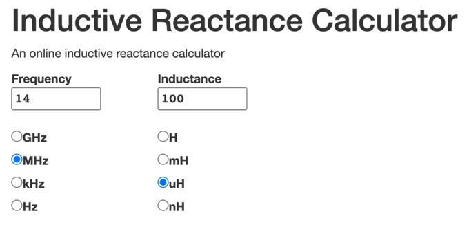 An online inductive reactance calculator, accepts as input Frequency and Inductance
 -
 Chavdar Levkov, LZ1AQ, presents an experimental comparison of small wideband magnetic loops, building on his previous work on wideband active small magnetic loop antennas. His research focuses on increasing loop sensitivity by maximizing the short-circuit current, which is directly tied to the "loop factor" M = A/L, where A is the equivalent loop area and L is its inductance. Levkov's methodology involves reducing inductance and increasing area through parallel or coplanar crossed (CC) configurations, comparing these designs against a reference single quad loop of 1 m2 area. Experimental verification included testing three distinct loop types: a simple quad loop, two coplanar crossed (CC) loops, and eight parallel loops, all designed to have a total geometric area of 1 m2. Measurements were conducted at 1.8, 3.5, 7, and 10 MHz using a small transmitter 270 meters away, with a Perseus direct sampling receiver for precise signal level assessment. The results consistently showed that CC loops, particularly Loop 5 (two CC circular loops with 1.44 m2 total area), yielded significantly higher currents, up to 9.1 dB over the reference loop at 3.5 MHz, validating M as a reliable predictor of loop sensitivity. Numerical simulations using MMANA further corroborated the experimental findings, demonstrating an almost perfect correlation between the calculated M factor and the induced loop current for 15 different loop models. Levkov concludes that CC loops offer superior sensitivity for a given loop area, while parallel loops are advantageous for minimizing physical volume. Practical recommendations suggest using loops with an M factor greater than 0.5 uA/pT for quiet rural environments, and he provides a spreadsheet tool, WLoop_calc.xls, to aid in optimizing loop configurations for specific operational needs.
 -
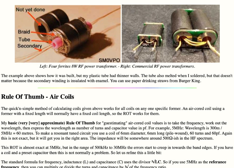 Demonstrates practical **rules of thumb** for selecting and utilizing ferrites and coils in amateur radio projects, particularly for RF applications up to 30 MHz. It addresses common challenges like determining appropriate ferrite grades and estimating L/C values without precise specifications. The resource details the author's experience with readily available grey ferrites, noting their suitability for HF work, and provides guidance on constructing **baluns** and RF chokes, balancing inductance for lower frequencies against inter-wire capacitance for higher frequencies. It also outlines a method for estimating power handling based on ferrite weight, suggesting a 1-gram ferrite can manage over 2 Watts, and offers a technique for evaluating unknown ferrites by winding 10 turns and measuring resonance with a 1 nF capacitor. This approach emphasizes a hands-on, iterative method for balun winding and adjustment, allowing operators to quickly approximate component values. The article compares the characteristics of ferrite-cored coils with air-cored coils, highlighting the reduced pickup and radiation of ferrite designs. It refines the air-coil estimation method for frequencies between 2.5 MHz and 10 MHz and provides a scaling factor for frequencies outside this range, aiming to get operators into the correct general area for their designs. The author's standardized ferrite choice (RND Components 165-00182) is presented as a practical example for reproducible projects.
 -
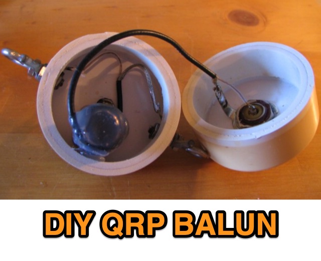 DIY project of a QRP Balun. Using a high permeability ferrite rod and an old B&W dipole center insulator, he constructs a choke type balun for QRP use. The balun aims to create as much inductance as possible at HF, offering a high impedance to common mode currents
 -
 A 5/8-wavelength vertical antenna for 2-meter FM operation is detailed, focusing on eliminating loading coils by utilizing a series inductor to cancel capacitive reactance at the feed point, thereby presenting a 50-ohm impedance match. The design illustrates three basic configurations, including a method employing a short-circuited coaxial stub for inductance, as implemented by K4LPQ. An alternative design is presented where the center conductor of the stub is extended one-quarter wavelength, creating a signal-frequency short and allowing for an insulated wire stub to develop the required series inductance. The article provides electrical theory and mechanical considerations for building the antenna, emphasizing the adjustment of stub length for proper impedance matching. This technical documentation is intended for amateur radio operators interested in homebrewing VHF antennas, offering practical insights into impedance matching techniques for vertical radiators.
 -
 The POCKET TUNER V1.1 is a highly compact HF T-Match antenna tuner designed for QRPp and QRP portable operations. With a credit card-sized form factor, it is tailored for low-power setups, supporting HF bands from 10m to 40m. The tuner features a unique design using rotary switches for precise capacitor adjustments, allowing tuning in small increments. Its inductance selection is optimized for various bands, ensuring efficient performance. Equipped with a resistive tuning indicator, it protects the transmitter by reducing SWR during adjustments. This versatile and portable tuner is ideal for field operations, enabling efficient antenna matching for low-power rigs.
 -
 Online impedance calculators grouped by types like Wire inductances, Toroid incuctances, Plane, PAD, Strap inductances, but even Core and Coax Inductances. Air core inductances and mutual inductance groups are also availbale. All these calculators let you input specific paramenters based on the inductor selected and will calculate specific incutance and related dimensions.
 -
 Demonstrates the construction of an active loop converter specifically designed for the Low Frequency (LF) bands, addressing common localized noise interference in LF reception. The design integrates a sharply tuned circuit and a tuned loop antenna, utilizing the loop as the sole tuned inductive element. By applying positive feedback, the converter significantly increases the loop's effective Q, achieving factors between 1000 and 2000, which sharpens tuning and reduces noise. The circuit employs an _NE602_ mixer stage, feeding its output to an HF receiver, with a crystal-locked local oscillator at 4 MHz. A 20-turn, 0.8-meter square loop antenna with 500 uH inductance is detailed, connected via 2 meters of figure 8 flex cable. The converter offers three selectable frequency bands: 195-490 kHz, 150-220 kHz (including the New Zealand amateur band), and 128-160 kHz (covering the European amateur band). Performance measurements indicate an effective 3dB bandwidth of approximately 100 to 200 hertz at 200 kHz. The article provides insights into component selection, including an _LF353_ op-amp and a trifilar wound transformer on a ferrite core. Sensitivity figures are presented, showing 7.5 uV of converted output per 1 uV/meter signal strength into a 50-ohm load, or 37.5 uV into an _FRG7_ receiver, highlighting its capability to extract weak signals from noise.
 -
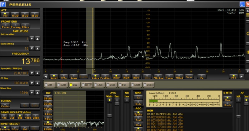 Investigates the performance characteristics of the _AAA-1_ active loop antenna across Very Low Frequency (VLF) and Low Frequency (LF) bands. It details the antenna's frequency response, explaining how a small loop with a low input resistance trans-impedance amplifier maintains a flat frequency response to electromagnetic field intensity E. The document illustrates current source and Thevenen equivalent circuit models for small loops, emphasizing the transition between these models based on frequency and load impedance. Measurement setups for both high frequency and VLF/LF responses are presented with diagrams, including methods for simulating current and voltage sources. The analysis includes normalized plots of the _AAA-1_'s frequency response for three distinct loop inductances, derived from measurements using a _Perseus SDR_ at 1 kHz bandwidth. It provides calculations for the noise floor at VLF/LF frequencies, comparing ambient noise levels with the antenna's internal noise floor. The resource also documents practical reception experiments in a semi-urban environment, showcasing successful reception of time transmitters like _MSF_ at 60 KHz and _SAQ_ at 17.2 KHz, along with various navy digital transmissions and Russian Alfa beacons.
 -
 Online Coil Inductance Calculator. To calculate the inductance of a single-layer, air-core coil, just select the measurement units, enter the number of turns, the coil diameter and the coil length.
 -
 A common mode choke/balun, essential for mitigating common mode current on antenna feedlines, is detailed in this construction and measurement guide. It utilizes eight Fair-Rite #2643167851 Mix 43 ferrites housed within a Hammond 1598JSGYPBK plastic case, with RG-8X coax cable forming the windings. The document references design principles from Ian White, GM3SEK's article on cost-effective ferrite chokes. Specific construction details include the layout of three coils to minimize inter-coil coupling and methods for securing the ferrites with foam tape. The resource presents comprehensive measured data, including isolation impedance (magnitude, real, and imaginary components), Q factor, inductance, and phase angle across various frequencies. It also covers the choke/balun's coax frequency response and return loss characteristics. Techniques for measuring choking impedance are thoroughly explained, focusing on S21 transmission measurements with a Vector Network Analyzer (VNA) and testing ferrite beads in both S11 and S21 modes. The guide describes a practical setup using an aluminum sheet or baking foil for measurements and outlines the calculation of series impedance from attenuation in a 50-ohm system. Additionally, it details a method for determining the balun's equivalent L and C around resonance by adding a parallel capacitor.
 -
 Demonstrates the design and modeling of a **160m** vertical antenna, dubbed the "WindoVert," specifically for urban amateur radio operators with limited space. The resource covers the theoretical underpinnings of antenna height and radiation patterns, using EZNEC software to analyze current distribution and 3D radiation patterns for various configurations, including a Marconi-style "T" antenna. It details the integration of existing antenna components, such as a Carolina Windom balun and line isolator, into the new vertical setup, and the practical measurement of feedpoint impedance using an antenna analyzer. The article further explores the challenges of achieving low-angle radiation on Top Band, emphasizing the critical role of radial systems and mitigating ground loss. Author VE1ZAC presents EZNEC models illustrating the impact of lumped components and discusses the practical considerations of resonant frequency adjustment and impedance matching for **QRP** operation. The text details the calculation of required loading coil inductance and capacitance, and shares field results, including successful DX contacts on 160m and unexpected excellent performance on 30m.
 -
 VE2AZX's 2013 Radio Talk presentation details the technical aspects of baluns, including reasons for their use, various types, and methods for performance verification using an SWR analyzer. The document specifically examines 1:1 voltage baluns and 4:1 voltage baluns, outlining their winding configurations and typical impedance transformations. It presents empirical SWR measurements for W2AU 1:1 baluns and Unadilla 4:1 baluns, tested with both 50-ohm and 200-ohm resistive loads across the HF spectrum. The presentation further explores the measurement of ferrite impedance and their application in mitigating common-mode currents on feeders and household conductors. Key concepts addressed include balanced-to-unbalanced transformation, ensuring feeder independence from the antenna, and reducing unwanted feeder radiation. The content emphasizes practical testing procedures to ensure optimal antenna system performance and minimize RF interference. Discussions also cover open-circuit tests with SWR analyzers and VNAs to assess winding inductance, distributed capacitance, and insulation quality. The presentation differentiates between voltage and current baluns, explaining how current baluns, particularly those utilizing ferrite cores, reduce outer shield currents without affecting internal coaxial cable currents, thereby preserving the antenna's intended radiation pattern.