Search results
Query: micro controller
Links: 62 | Categories: 2
-
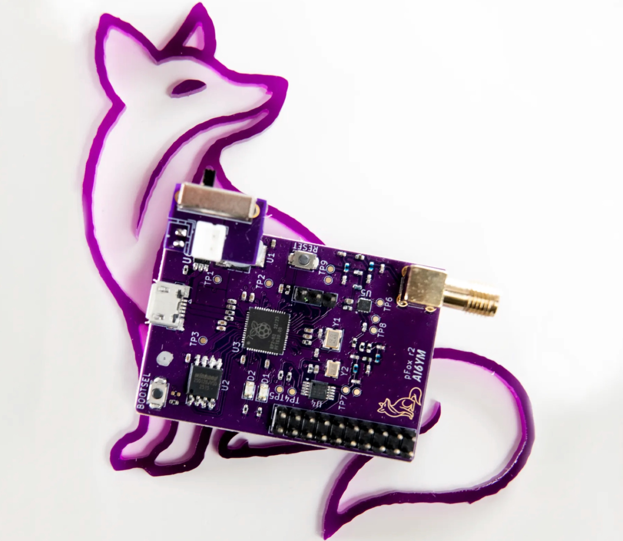 The PicoFox is a versatile fox transmitter for 2-meter ham radio operators, built around the RP2040 microcontroller. With open-source hardware and software, it can be customized to suit your needs, from APRS to other digital modes. This fully assembled transmitter comes with a rechargeable battery and antenna, ready for use. The design allows for easy addition of features like sensors or interactivity. Modulation is handled in software for smooth FM output, with ample CPU, flash, and GPIO available. Configure your PicoFox by connecting it to a computer via USB and adjusting settings in a text file. Explore the possibilities of this innovative transmitter for your amateur radio projects.
 -
 This page provides a detailed guide on how to receive WWVB 60 KHz time signals using the Everset ES100 module with an Arduino Due microcontroller. It explains the background of time standards and the significance of WWV radio stations in maintaining these standards. The content is useful for ham radio operators interested in time synchronization, scientific research, navigation, and radio communications. The article is written by Keith Greiner, who shares his project inspired by his passion for the subject. For more projects by the author, visit the provided links.
 -
 An **Arduino LC Meter** provides an accessible solution for precisely measuring inductance and capacitance values, crucial for RF circuit design, filter tuning, and troubleshooting in amateur radio applications. This project details the construction of a low-cost, accurate instrument using readily available components, making it an attractive alternative to commercial units for hams and electronics enthusiasts. The build process involves assembling a resonant circuit, integrating an Arduino microcontroller for frequency measurement, and displaying results on an LCD. Key components include an Arduino Uno, a 16x2 LCD, a 74HC14 Schmitt trigger inverter, and a few passive components. The design leverages the Arduino's processing power to calculate L and C values from resonant frequency shifts. Calibration procedures are outlined to ensure measurement accuracy, which is vital for critical RF work. The project includes schematics, a parts list, and the necessary Arduino code, enabling hams to construct a functional LC meter for their workbench.
 -
 The resource details the construction of a 433 MHz LoRa APRS iGate and a tracker, both built around _TTGO T-Beam v1.1_ microcontroller boards. Each board integrates an OLED screen, WiFi, GPS, and an SMA antenna connector, powered by an 18650 3.7 V lithium-ion battery or microUSB. The iGate operates on 433.775 MHz, with its status verifiable on aprs.fi, demonstrating practical implementation of LoRa-based APRS solutions. The methodology involves programming the modules using Visual Studio Code with the PlatformIO plugin. This process loads the necessary firmware and a JSON configuration file, which includes the operator's callsign and WiFi credentials for the iGate. The guide emphasizes the ease of programming and provides specific steps for configuration. Initial testing of the iGate and tracker, including smart beaconing configuration, is documented. The low power output of approximately 200 mW from the LoRa board's transmitter is noted, with suggestions for range extension through improved antennas or RF amplification. The author, N4MI, plans to deploy a higher-gain 70cm antenna for the iGate.
 -
 The DIY Power Meter project utilizes the _INA226_ high-side power monitoring chip, paired with an ATtiny85 microcontroller, to measure voltage, current, and power, displaying the results on a 128x32 OLED screen. The INA226 communicates via an I2C interface and is programmed with a calibration factor based on the shunt resistance and current register LSB. The project is designed to handle a maximum current of 500mA using a 0.16ohm shunt resistor, which can be adjusted to a 0.2ohm resistor, reducing the full-scale current range to 409mA with a resolution of **12.5uA**. The shunt resistor dissipates only 33mW at maximum current, making 1/4 watt resistors suitable for the setup. The PowerMeter.ino sketch configures the shunt resistance and maximum design current, automatically calculating the calibration factor. The project can be prototyped on a breadboard using an Arduino Uno, employing the Wire library for INA226 and OLED communication, and the u8g2lib library for the OLED display. For the ATtiny85 version, the Adafruit-TinyWireM and Tiny4kOLED libraries are used. The power meter is independently powered by a 3V CR2032 cell, with power switching options including manual switches or DC switched jacks. The low-side n-channel MOSFET switch configuration is tested but introduces voltage drop issues, making manual switching a more reliable option until a suitable DC switched jack is found. DXZone Technical Profile: INA226 | ATtiny85 | OLED Display | Power Meter
 -
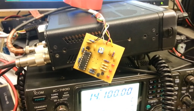 This project details an automatic roger beep circuit for VHF/UHF contests. Built around a Microchip PIC microcontroller, the design detects PTT (Push-To-Talk) activation and generates a brief tone upon release, mimicking a "roger beep" to signal the end of transmission. The circuit utilizes readily available components and includes downloadable resources for PCB layout and firmware.
 -
 This project outlines a simple Lead Acid/SLA battery monitor, designed to alert users when battery voltage falls below 10.6V. The monitor, based on a PIC16F1827 microcontroller, checks the voltage of up to five batteries and triggers an alarm if any drop too low. The system operates in various modes, including self-test, monitoring, and alarm. This updated version improves upon the original 1999 design, offering a more modern microcontroller and extended functionality for workshop use, with minimal impact on battery charge.
 -
 A versatile digital VFO design utilizing the Silicon Labs Si5351a oscillator chip and Nokia 5110/3310 graphics LCD display, operating from 1-160MHz with dual VFO capability. This microcontroller-based system, powered by an ATmega328 processor, features rotary encoder tuning, selectable step sizes, RIT control, and comprehensive band memory functions. Drawing less than 40mA at 3.3V, it significantly improves upon previous DDS designs' power consumption while offering advanced features like S-meter display, VFO lock, and programmable BFO/CIO offsets. The design achieves flexible functionality through simple hardware implementation and efficient software architecture, making it particularly suitable for QRP and portable amateur radio applications.
 -
 The project aims to create a remote control system for the VK5RSE beacons located near Millicent, South Australia. The beacons on 144.550, 432.550, and 1296.550 MHz can interfere with nearby amateur radio operations, particularly for EME work on 1296 MHz. The remote control system uses a DTMF decoder and PIC microcontroller to allow turning the beacons on and off individually or in combination. The system is housed in a diecast box and powered from 5-8V. The password-protected control allows authorized users to manage the beacon operations remotely, helping mitigate interference issues for local amateurs.
 -
 The W6PQL 23cm Beacon Project describes a **1296 MHz** beacon designed for microwave propagation studies and equipment testing, capable of 30 watts output. It utilizes a PIC 16F628A microcontroller to generate CW and FSK keying for a crystal oscillator, followed by a series of frequency doublers and triplers to reach the target frequency. The final power amplification stage employs a Mitsubishi M57762 module, providing a robust 10-watt RF output. The design emphasizes stability and reliability for continuous operation, with the microcontroller code, written in assembly, provided for customization of the beacon's callsign and message. Originally located in CM97am and aimed at 140 true, the beacon used four 4-foot Yagis stacked vertically for a total ERP of 3kW. The article includes schematics, parts lists, and construction notes to guide builders, along with antenna pattern measurements. Although the beacon itself is no longer in service as of August 2010, the detailed documentation remains a valuable reference for amateur radio operators interested in building similar **microwave** projects or understanding beacon operation.
 -
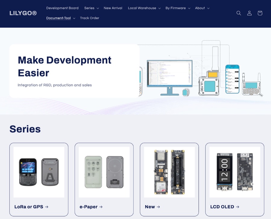 LILYGO specializes in the research and development of IoT solutions, offering a diverse range of development boards. Key products integrate LoRa and GPS capabilities, alongside various display options such as LCD and OLED. Specific examples include the _T-SIM / T-A Standard Series_, _T5 E-Paper S3 Pro Lite_, _T-Halow P4_, _T-Dongle C5_, and _T7-C5_. The company also provides the _T-Solar Kit_ and _T-Sim Shield_, catering to diverse project requirements. Hot sales items feature the _T-Display S3_, _T-Embed CC1101_, _T-Deck Plus_, _T-Embed CC1101 Plus_, _T-Deck Plus Meshtastic_, _T3 LoRa32 V1.6.1_, and _T-Display S3 AMOLED_. These boards often incorporate ESP32 microcontrollers, facilitating wireless communication and display functionalities essential for amateur radio digital modes and data telemetry applications. LILYGO provides entry-level sample code for most products, aiding learners in rapid prototyping and deployment. They also offer customization support for specific customer needs, demonstrating a commitment to supporting both individual makers and larger-scale integrations. The company actively participates in events like Maker Faire Rome, showcasing open-source solutions to the global maker community.
 -
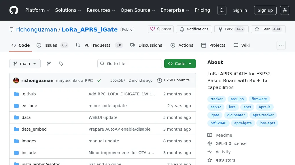 Demonstrates firmware for microcontrollers like the _ESP32_ to implement a LoRa APRS iGate and Digipeater. This project leverages LoRa for packet radio communication, allowing amateur radio operators to bridge the gap between LoRa-enabled APRS stations and the global APRS-IS network via WiFi. It details the setup for both iGate and Digipeater modes, including features like transmitting APRS-IS packets over LoRa to local stations and a 30-second buffer in digipeater mode to prevent packet storms. This firmware offers an Ultra Eco Mode, achieving current consumption between **7mA** and **13mA**, making it suitable for remote, battery-powered deployments. The integrated WebUI simplifies configuration and management, providing an accessible interface for hams to deploy and maintain their LoRa APRS infrastructure. It supports sending weather telemetry packets and adheres to APRS protocols, released under the GPL-3.0 license.