Search results
Query: 80m antenna
Links: 137 | Categories: 2
Categories
-
 Top Loaded Vertical Antenna 3,5 MHz 80m and a 14 MHz Trap for the 20m band. The weight of this portable vertical antenna is less than 1 kg, including the ground network. The weight of the telescopic fiberglass fishing rod is another 1kg. The rod expands from 1.5 meters to 8 meters.
 -
 Homemade receiver for 80 meters band. The receiver works very well (in fact better than some of its successors), especially the AGC makes listening to 80m QSOs a real pleasure. Sensitivity is not cutting-edge, but on a full-size short-wave antenna it is by fare sensitive enough.
 -
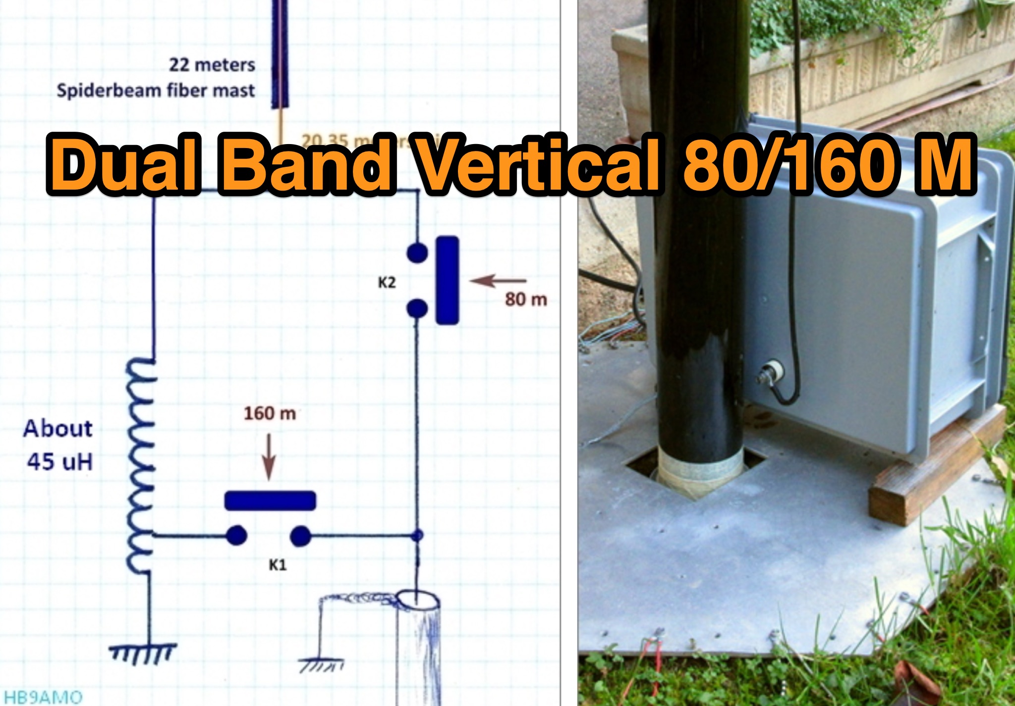
 A dual band vertical antenna for 160 and 80 meters band, on a 18m spiderbeam fiberglass pole. This vertical is a good compromise when you want good performance on these two low ham bands and don't have the space to install two seperate antennas.
 -
 Operating in a Single Operator Two Radios (SO2R) setup, especially with beverage antennas, often exposes the receiving radio's front-end to significant RF energy from the transmitting radio. This resource details a practical, homebrew receiver protection circuit designed to mitigate this risk. The core of the design involves a non-inductive 2W 22 Ohm carbon composition resistor in series with the RX antenna line, followed by two stacks of four fast-switching diodes (e.g., _1N914_) configured in opposite polarizations. This arrangement effectively clamps the incoming voltage to approximately 2.8 V peak-to-peak, safeguarding sensitive receiver input components. The series resistor plays a crucial role by absorbing excess power, preventing the diodes from exceeding their current ratings and potentially failing open, which would leave the receiver unprotected. The author, _N4KG_, measured up to 50 watts of coupled power between 80M slopers on the same tower, highlighting the necessity of such protection. The design is presented as a cost-effective solution to prevent damage to receiver input transformers, with the author noting successful protection of a receiver even after a resistor showed signs of overheating. This simple circuit can be integrated via a transverter plug, offering a robust defense against high RF input.
 -
 No matching adjustments needed. Directly perfect match to 50 Ohms using a remotely switched wideband transformer
 -
 A 3 band dipole antenna for 40-80-160 meter bands, It's made with easily available materials and is designed for inverted V mounting. The antenna is shortened for these bands, but still manages to make contacts in 80m and 160m with stations in Canada and the USA. The construction details are provided, including the dimensions of the antenna elements and the traps. The antenna is easy to build and provides good performance in all three bands. In Italian.
 -
 A dedicaed vertical antenna for 80 meters band based on a 40 meter vertical experiment
 -
 This antenna just requires about 24m of free space instead of 41m that a normal half wave 80m antenna needs to hang up. The so called loaded dipole uses a coil in every dipole arm to electrically lengthen the mechanical too short dipole arms. Every coil has an inductivity of 120 microHenry.
 -
 This article describes a simple yet effective multi-band vertical HF antenna design that performs exceptionally well across 80m to 10m bands. The antenna consists of a 13.4m wire mounted on a 12.4m Spiderpole, complemented by four 12m radials and a ground rod. Initially tuned with a manual LC circuit, it was later upgraded with a CG3000 remote auto ATU for convenient band switching. Despite antenna modeling software suggesting limited performance on higher frequencies, the system demonstrated excellent DX capabilities across all bands, outperforming more complex vertical antenna designs.
 -
 Listen to online WebSDR located in Andorra Europe. Four receivers on 60m, 20m, 40m, and 80m, connected to a dipole antenna direction East/West
 -
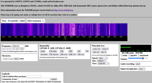 This WEBSDR runs on Raspberry PI4-8G, Afedri-Net RX for 160m, RTL-SDR stick with homemade SBL1 mixer upconverter and fullsize 160m Delta loop antenna 4m up. Operated from Ukraine by UR5WT, US5WE and UX5DH,
 -
 Experimentin wire antennas on top band using several type of aerials. This includes a 40 to 160 meters EndFed Half Wave kite antennas and 160m/80m loaded vertical antenna.
 -
 This page provides detailed information on various antenna designs specifically tailored for hams operating on the 80m and 160m bands. The article covers the pourpose and usefulness of each design, helping hams optimize their radio communication capabilities on these popular bands. Whether you are a beginner looking to improve your setup or an experienced operator seeking new ideas, this page offers valuable insights to enhance your ham radio experience on the 80m and 160m frequencies.
 -
 A dual band 40-80 vertical antenna on an 18m Spiderbeam Fiberglass Spiderpole, with monoband performance
 -
 This article documents the author's journey in building, modifying, and testing a DIY short vertical antenna for 40, 30, and 20 meters, with potential 80m capability. Initially inspired by Parks On The Air (POTA), the author explores pedestrian mobile operation and details various experiments to enhance antenna performance. The piece highlights challenges, SWR tuning, portability, and practical results, emphasizing a balance between efficiency and size. Ultimately, it showcases the adaptability of DIY antennas for portable ham radio applications.
 -
 The author reflects on expanding their antenna for 80m coverage during lockdown. They extend the End Fed Half Wave (EFHW) using a Spiderbeam pole and "cheating" by dog-legging across their garden. Despite challenges, they achieve coverage for multiple bands with minimal cost. Practical Wireless features EFHW antennas, including a pre-made 20m EFHW extended for 40m.
 -
 An Inverted-L with its long leg sloping to the ground. It will still work very good, even if the horizontal wire has to be sloped diagonally to the ground, as long as you have enough horizontal space to keep it at about a 45 degree angle or more from the pole.
 -
 Dipole for 40m band. It is a simple linear loaded dipole feeded with 450-Ohm openwire feedline. Designed it for resonance at 7.050 MHz, can be tuned on 30m and 80m bands with an external antenna tuner. Build with simple electrical copper wire (2.5 mmq/13 awg) and two fishing poles with size of about 7 m/23 ft.
 -
 The 80-meter Skyloop antenna, a top-performing HF antenna, excels in weak signal work, low-noise operation, and omnidirectional coverage. Ideal for fixed stations, it delivers strong performance at low power, outperforming many alternatives, including 80m half-wave end-fed antennas. Requiring significant space for deployment, it’s well-suited for NVIS and groundwave use. Though not portable, it’s cost-effective and durable, with minor maintenance needs. Tuning may require adjustments for optimal resonance. It’s a standout for base stations, though a lighter portable version could enhance its versatility.
 -
 How to Design and Build a Field Expedient End-Fed Half-Wave Antenna for 20m, 40m and 80m. This Shorty 80m EFHW comprises a 49:1 autotransformer (to match the very high impedance at the end of a half-wave wire), a half-wavelength wire for 40m (also a quarter-wavelength for 80m), a loading coil and a short tail wire. The coil and the short tail wire (about 6 feet) make up the other quarter wave on 80m.
 -
 Learn how to design and analyze a folded trifilar antenna for the 80-meter band. Based on a description from RAF antennas between 1940 and 1970, this article provides step-by-step guidance on modeling the antenna, calculating resonance frequency, adjusting dimensions, and verifying performance. Perfect for hams looking to improve their antenna setup for better transmission and reception on the 80M band.
 -
 Schemaric diagram for a 80m, 40m, 30m, 20m EFHW Antenna Antenna Tuner. The tuner has been designed for an antenna length of 41m and the counterpoise 7.5m.
 -
 Integrating a **160-meter vertical wire antenna** with an existing 80-meter Yagi system presents unique challenges for Top Band operation. This project outlines the author's experiences with seasonal antenna removal and reinstallation, a necessary task for agricultural land use. It details specific issues encountered, such as incorrect coil sizing and relay configuration problems, providing practical insights into common pitfalls. The article describes the iterative tuning process, comparing **NEC model** predictions with actual on-air performance. It emphasizes the importance of precise measurements and adjustments to achieve optimal resonance and impedance matching. The author shares lessons learned from troubleshooting, including the impact of ground system integrity and feedline considerations. Concluding with an antenna checkup, the resource addresses long-term maintenance aspects, including galvanic corrosion prevention and general upkeep for reliable operation.
 -
 This is a FULL SIZE quarter-wavelength vertical made on a 18m Spiderbeam fiberglass telescoping Spiderpole
 -
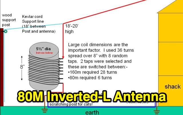 80m Inverted-L Antenna, Base-loaded for 160m antenna. This antenna is not a good DX antenna however within small garden where true DX antennas would be impossible it has performed very well.
 -
 WB8LZR details the construction and initial field results of a multi-band vertical wire antenna, designed to complement his existing horizontal loop for improved DX on 80 meters. The antenna utilizes a 67-foot vertical wire, configured as a quarter-wave radiator on 80m, and employs a 1:1 current balun for RF isolation on 80m, 30m, and 17m. For bands like 40m, 20m, and 10m, where the wire acts as a half-wave or full-wave radiator, an additional impedance transforming _unun_ is integrated to manage the significantly higher feedpoint impedance and voltage. The author notes the vertical's performance as a receiving antenna, observing reduced noise compared to his main horizontal loop, particularly on 80m, and even hearing some long-path signals the loop missed. Initial QRP contacts, including a **1-watt** QSO with a _VP2 station_ on 30m, demonstrate its transmit capability. While the radial system is currently rudimentary, the project outlines practical considerations for multi-band vertical deployment and impedance matching.
 -
 A half wave wire that is tuned for resonance on 80m will NOT be resonant on 40m despite a precise harmonic relationship between the two bands. The End Effect is caused by a capacitive coupling between an unterminated wire end and the ground.
 -
 The Butternut HF2V, originally a two-band vertical antenna for 80m and 40m, was enhanced by the user to include 30m and 20m bands for better digimode DX work during the solar minimum. The additions used components adapted from the HF6V and innovative methods for the 20m addition, either through a parallel vertical element or a lower-mounted independent element, minimizing band interaction. This modified four-band antenna now supports high power across popular HF bands using a single feedpoint.
 -
 From March 2 to March 11, 2018, a Norwegian team operated as Z2LA from Zimbabwe, focusing on 160m through 10m bands using SSB and CW modes. The operation, described as "holiday style," aimed to provide contacts for DXers worldwide seeking a rare DXCC entity. Key equipment included a SUNSDR PRO II, an Elecraft KX3, and an Icom 706 MK2G as a spare radio, supported by two Juma 1000 amplifiers for robust signal output across the bands. Antenna systems were tailored for multi-band operation, featuring an Inv L for 160m and 80m, sloping dipoles for 30m/40m, and a _Hexbeam_ from SP7IDX Technology covering 20m to 10m. For improved reception, the team deployed a SAL 30, two reversible BEV antennas from remoteqth.com, and a BOG from K1FZ, enhancing their ability to hear weak signals. QSL information directs operators to Clublog for log search and M0OXO Charles for OQRS, explicitly requesting no bureau cards. The team comprised LA7THA Rune, LA7WCA Arne, and LA9VPA Thor, successfully making numerous contacts and contributing to the DX community's pursuit of _Zimbabwe_ as a DXCC entity.
 -
 This article details the development of an 80-meter antenna within the confines of a restrictive covenant community. Faced with limited space, the author explores various options before implementing a clever hybrid design: a short 30-foot vertical wire running discreetly down the building's exterior combined with a capacitive top hat installed in the attic. Computer modeling confirmed the superiority of capacitive loading over inductive loading, increasing radiation resistance from 6 to 14 ohms. The perimeter wire top hat, naturally supported by the attic structure, resonates effectively at 3.5 MHz. The system is completed with four buried 60-foot radials installed "after dark" to maintain compliance with community restrictions.
 -
 The LKJ Wednesday Night Special Antenna, designed by John Whiteman K5LKJ, is a compact 50-foot coil-loaded dipole for 80-meter operation, ideal for space-limited hams in residential areas. Using two 1-inch diameter PVC coils with 87 turns of #16 magnet wire each—placed 10 feet from the center—it tunes to 3.910 MHz for local nets like BVARC Rag Chew. Constructed with #14 wire, ceramic insulators, and Mini-8X feedline, it handles 1000W, performs well at low heights for NVIS, and requires a tuner for bandwidth. Collaborative tuning by club members ensured success.
 -
 The tri-band trapped delta loop antenna design operates on 80 meters (3.5–4 MHz), 40 meters (7–7.3 MHz), and 30 meters (10.1–10.15 MHz) using a single triangular wire loop. This configuration eliminates the need for an external antenna tuner or band-switching relays. The antenna's physical perimeter, approximately 270 feet, establishes 80M as the fundamental band, with specific trap placements enabling resonance on 40M and 30M. Trap design and placement are critical, with 30M traps positioned inboard of 40M traps within the horizontal element. Each slant leg measures approximately 80 feet. The resource references foundational information from the _ARRL Antenna Handbook_ and _ON4UN’s Low Band DXing_ regarding full-wave loop behavior and feedpoint impedances. The project aims to provide multi-band HF operation from a single, fixed antenna structure.
 -
 Presents DJ5IL's personal amateur radio station, detailing his journey as a licensed operator since 1973. The resource covers his **shack setup**, including an Elecraft K4D, Icom IC-7610, and various vintage transceivers like the Drake 2-B, along with a SPE Expert 1K-FA amplifier. Antenna systems include a PRO.SIS.TEL RD1524T rotary dipole for 40/20/15/10m at 15m height, an 18m vertical dipole with an SGC SG-230 tuner for 3.5-30 MHz, and an inverted-V dipole for 80m. The site features a **QSL gallery** showcasing his custom card designs and outlines his QSL policy, emphasizing the exchange of unique, personalized cards over generic confirmations. It also includes a detailed operator's biography, tracing his early fascination with radio, obtaining his license at 16, and memorable QSOs, such as a contact with his blood-relative W3NZ. The resource also delves into the historical significance of amateur radio's role in pioneering shortwave communication following the 1912 International Radiotelegraph Convention, which initially relegated amateurs to wavelengths of 200 meters and shorter. DJ5IL's philosophy on "ham spirit" is discussed, stressing the unpolitical nature of amateur radio as a global fraternity.
 -
 This article from the July 1976 issue of Radio REF discusses the trend of large antennas for ham radio operators on the low bands. It specifically focuses on a Yagi 2 element antenna for the 80m band, detailing its construction and functionality. The author explains how the antenna can be switched between directing signals towards the West or East using a switch at the station. The article also provides technical details on the lengths of the director and reflector elements, and how they impact the antenna's performance. A useful resource for hams looking to build or understand Yagi antennas for the 80m band.
 -
 Details the construction and performance of a phase-controlled receiving array, specifically a **MicroSWA** variant, optimized for QRP low band fox hunting on 40M and 80M. The resource documents the author's iterative design process, addressing significant regional noise challenges encountered during 0100-0230 UTC fox hunt periods. Initial experiments involved a director wire on a 40M vertical, yielding limited improvement, prompting a shift towards advanced null-steering techniques. The project leverages concepts from Victor Misek’s "The Beverage Antenna Handbook" and Dallas Lankford’s extensive work on phased receiving antennas for urban lots. A key modification involved integrating a new passive phase control box and a push-pull **Norton common base preamp** using 2N5109 transistors, designed for high third-order intercept performance to maintain weak signal integrity amidst strong adjacent signals. The system incorporates Faraday-shielded transformers with RG174 primaries on -75 ferrite cores, housed in ABS plastic pipe. Performance tests confirmed the MicroSWA's ability to produce deep, steerable nulls, achieving approximately 30 dB noise reduction on 160M, 80M, and 40M. This enabled detection of QRP signals undetectable on conventional transmit antennas. The final unit includes front panel controls, a 10-11 dB preamp, and a robust power conditioner, demonstrating effective noise mitigation for challenging low band QRP operations.
 -
 This page provides a detailed example of the modeling and analysis of an 80m delta dipole antenna with a 600-ohm bifilar feedline. The model is based on antennas used by the RAF from 1940 to 1970. It covers the original model specifications, conductor mass calculations, resonance frequency observation, geometry adjustment steps, and final antenna dimensions. The content includes theoretical formulas, resonance frequency calculations, and practical steps for adjusting the antenna for optimal performance. Overall, it serves as a practical guide for hams looking to understand and optimize the performance of a delta dipole antenna for the 80m band.
 -
 The XW4DX DXpedition website documents the amateur radio operation from Laos, a country ranked #98 on Clublog's Most Wanted list. This resource provides insights into the planning and execution of a significant DXpedition, including antenna choices like _Hexbeams_ at 14m, a 4-square for 40m, and a top-loaded vertical for 160m. The team, comprising operators such as _F4BKV Vincent_ and _F2DX Patrick_, focused on challenging paths, particularly towards the North American East Coast, where Laos is #41 most wanted. Operational constraints included prohibitions on 6m, 30m, 60m, and 80m bands within Laos, necessitating a focus on other HF frequencies, especially 160m and 40m. The expedition utilized up to five stations simultaneously, with equipment transportation being a major logistical challenge, partially mitigated by direct shipments from _Spiderbeam_ and donor support. The expedition ran from November 16th to 27th, 2023, with the complete XW4DX log uploaded to LoTW by December 23rd, 2023. This site serves as a historical record of their efforts to put Laos on the air for DXers worldwide.