Search results
Query: beam 2
Links: 298 | Categories: 5
-
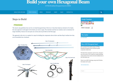 A web site dedicated to hex beam homebrewing. The hexagonal beam has become a wildly popular antenna. It is a directional antenna that provides great performance and does not require a full scale, expensive tower.
 -
 Exagonal Beam antenna cover 20-17-15-10 meters By KE4NU
 -
 A 6 dB gain Moxon rectangle antenna, designed for the 2-meter band, offers an excellent solution for hams seeking a compact, directional antenna for **SSB** operation, particularly in restricted spaces like an attic. This design emphasizes ease of construction using readily available materials such as 4mm OD brass tubing and plywood, making it an accessible project for many radio amateurs. The antenna's inherent characteristics, including a high front-to-back ratio of 37 dB and a 50-ohm feed impedance, contribute to its effectiveness in mitigating local noise and focusing radiated power. The project leverages the free MoxGen program for precise dimension calculations based on the desired frequency and wire size, and utilizes 4nec2 for pattern analysis, confirming a 3 dB beamwidth of 80 degrees. Construction involves bending brass tubing for the driven and passive elements, mounting them on an 800 x 350 mm plywood boom, and securing them with cable clips and epoxy resin. Initial SWR measurements at 144.3 MHz showed 1.6:1, which improved to 1.3:1 at 145.3 MHz across a flat band from 144.1 MHz to 145.5 MHz after adding a **coaxial choke** to mitigate common mode current.
 -
-
 This project details the construction of a **full-sized 40-meter vertical antenna**, born from a renewed interest in 7 MHz operation and a desire for improved effectiveness over simple dipoles. The author, K5DKZ, initially focused on VHF experimentation, which provided an inventory of aluminum tubing and fiberglass spreaders for this endeavor. Before this vertical, K5DKZ utilized an 80/40 meter inverted-vee trap dipole and a 40-meter broadband dipole, but now primarily uses a pair of full-sized, phased, quarter-wave verticals spaced 35 feet apart for serious 40-meter work. The construction involves a base-heavy design for stability, using a 44.5-inch section of 1-1/4 inch steel TV mast driven into 1-3/8 inch aluminum tubing, insulated by a 105-inch section of Schedule 40 PVC pipe. The assembly reaches 31 feet, close to the 32 feet required for a quarter-wavelength on 40 meters, with fine-tuning achieved by winding wire onto a fiberglass spreader. The design is explicitly presented as a foundation for a two-element 40-meter Yagi beam, outlining modifications like substituting aluminum for steel in the base and using an inductive hairpin match for the driven element. The article also discusses tuning considerations for a large 40-meter beam, noting the 100 to 200 kHz upward frequency shift when raised, and suggesting methods for installation on a tower. The author emphasizes the cost-effectiveness and good performance of the monopole approach, especially when multiple verticals are needed.
 -
 The Gizmotchy high performance horizontal and vertical beam antenna for 2/6/10/11 meter bands
 -
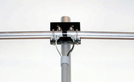 Design and build an 6 m dipole antenna from aluminum, tubing, that resembles the active element of a yagi beam antenna.
 -
 A fractional bandwidth of up to 30:1 characterizes spiral antennas, making them highly effective across a very wide frequency range, often from 1 GHz to 30 GHz. The resource details two primary types: the **Log-Periodic Spiral Antenna** and the **Archimedean Spiral Antenna**, defining each with specific polar functions and illustrating their planar configurations. It explains that spiral antennas are typically circularly polarized, with a Half-Power Beamwidth (HPBW) of approximately 70-90 degrees, and a peak radiation direction perpendicular to the spiral plane. The content elaborates on critical design parameters affecting radiation, including the total length (outer radius) for lowest frequency, the flare rate ('a' constant) for optimal radiation versus capacitive behavior, the feed structure (often an infinite balun) for high-frequency operation, and the number of turns (typically 1.5 to 3 turns). It also discusses the theoretical impedance of 188 Ohms for Log-Periodic spirals, derived from Babinet's Principle, noting actual impedances are often 100-150 Ohms. The article presents a simple construction method for an Archimedean spiral, demonstrating VSWR and efficiency measurements. Measurements from a constructed spiral antenna show a VSWR that is fairly constant across the band, albeit with a mismatch loss of about 3 dB. The antenna efficiency remains around -5 dB (31.6%) across its operating range, indicating a decent wideband radiator despite opportunities for optimization.
 -
 The AE6AC 17-meter Moxon antenna project details the construction of a wire beam using readily available materials. This design utilizes four 16-foot fiberglass crappie poles for support, joined at the center with 3/4-inch Schedule 40 PVC pipe and "T" slip fittings. Wire segment lengths for 18.135 MHz were calculated using _Moxgen_ software by AC6LA, with specific dimensions provided in feet and inches for precise cutting. Key construction decisions include joining the crappie pole bases into a central hub and attaching the 16-gauge silver-plated copper wire to the pole ends. Dacron cord with a fisherman's knot secures the wire to the pole tips, while small wire loops at the corners maintain antenna shape. Plexiglas pieces serve as insulators for sections "A" and "C." The finished antenna, weighing less than 10 pounds, mounts on a fiberglass windsurfer mast and incorporates a 1:1 current mode ferrite bead balun. Performance measurements with an _MFJ-259B_ show an SWR better than 1.5:1 across the 17m band, with good front-to-back ratio and reported signal strength improvements of 2-4 S-units over vertical dipoles. Initial contacts included VK2AXB, ZF6GS, and KL1M.
 -
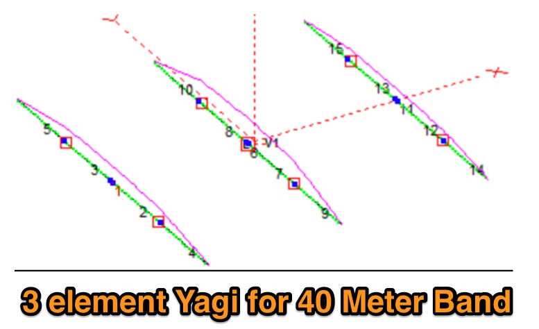 An homebrew project for a 3 element coil-loaded Yagi beam antenna for 40 Meter band
 -
 5-element antenna, with which G0JJL has worked lots of EU crossband, and won the RSGB Christmas Cumulatives 70MHz section twice in a row.
 -
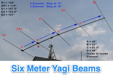 Article describing how to homebrew a yagi antenna for 50 MHz, includes plans for a four and five elements yagi beam and details how how match impedence with a gamma match
 -
 Antenna dealer, antenna masts, towers, mounts, antenna rotators, steppir and optibeam inrad dealer
 -
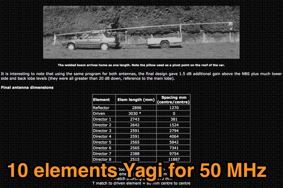 A homemade 10 element Yagi Beam Antenna for 50 Mhz by Rod Mackintosh, a NBS Yagi on a 13.2 metre boom.
 -

-
 Ground Plane - 1/4 wave vertical, J-Pole, 3 Element Yagi Beam and simple antenna supports
 -
 Fabricates baseplate components, and provides hardware kits for DIY hex beam, spiderbeam and moxon antennas.
 -
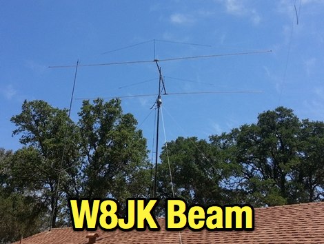 A compact 2 element W8JK beam antenna for 20M to 10M bands by AF6SA
 -
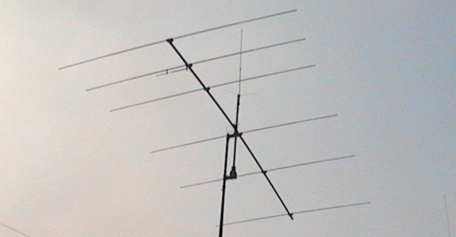 In this PDF article Zack Lau describe how to homebrew a four element yagi beam antenna for 50 MHz band, including how to build mounting blocks and tubing clamps to hold elements.
 -
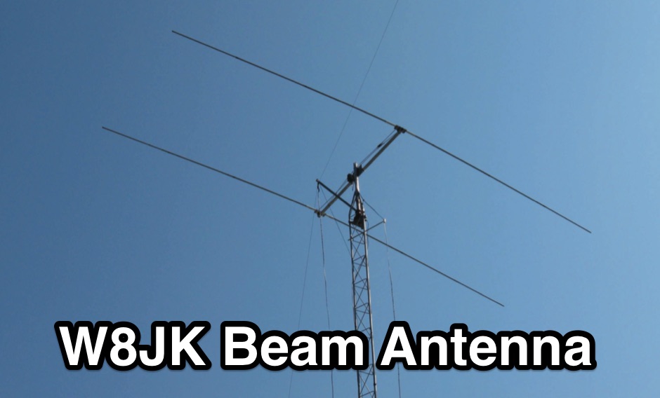 Examines the design and performance of a compact, efficient multiband beam antenna, based on a modified **W8JK array** by K5LJ. The author recounts his quest for a simple, compact, and reasonably efficient beam, initially using a single delta loop for 40 meters. He then details his modeling efforts with EZNEC, focusing on a W8JK array using 20-meter dipoles, noting its venerable design history in various Antenna Handbooks and QST. The resource explains how the classic W8JK array, composed of 0.5-lambda elements at the lowest operating frequency, uses a closely spaced phasing line to connect feedpoints, often 450-ohm ladder line. K5LJ's modifications, including offsetting the feedpoint on the phasing line, resulted in surprising gain and a somewhat unidirectional pattern on 20 meters, rivaling a full-sized Yagi. The article also delves into mechanical construction details, using nested tubing and PVC pipe for element isolation, and discusses the feedpoint impedance characteristics across multiple HF bands.
 -
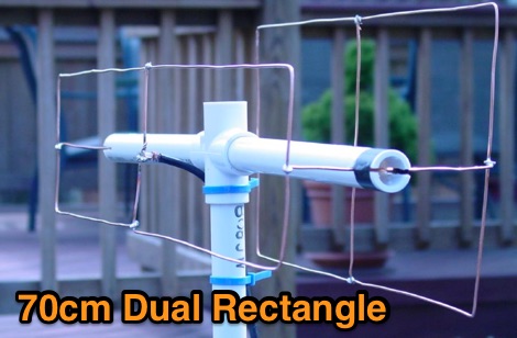 The antenna described here is a direct-connect dual-rectangle beam for use on 70 cm between 440 and 450 MHz
 -
 Constructing a compact, single-feed triband Moxon antenna for 20, 15, and 10 meters is detailed by DU1RZ, drawing from his personal experience with space-constrained antenna projects. Initially fascinated by cubical quads, the author transitioned to Moxon designs in 2005 after realizing his roof space was insufficient for a bulky quad. His first experimental monoband Moxon for 15 meters, built from repurposed materials, provided solid DX QSOs for seven years, despite being slightly below the 21 MHz band center. The project outlines the design process, including using the _MOXGEN Calculator_ for element dimensions and material selection, such as #14 AWG enamel copper wire and fishing poles for spreaders. DU1RZ shares insights from simulations with DL2GMS regarding insulated versus non-insulated wire performance, noting that insulated wire can shift resonant frequencies lower. The assembly instructions cover preparing wire elements, connecting feed points, and tuning the antenna, with initial SWR measurements taken at 10 feet and final readings on a mast showing excellent results: 1.0:1 on 14.225 MHz, 1.1:1 on 21.250 MHz, and 1.3:1 on 28.50 MHz. Transmission tests with 4F1BYN indicated a front-to-back ratio of approximately 2 S units with 10 watts output. The author emphasizes adaptability, encouraging builders to use readily available materials rather than strictly replicating his setup. Key observations from DU1RZ and DL2GMS highlight the antenna's strong performance across 20, 15, and 10 meters, good front-to-back ratio, full bandwidth on 20 and 15 meters, and its small turning radius of about 4.18 meters (13.54 feet), making it suitable for limited antenna space. Its lightweight construction and low wind load are also noted as significant advantages.
 -
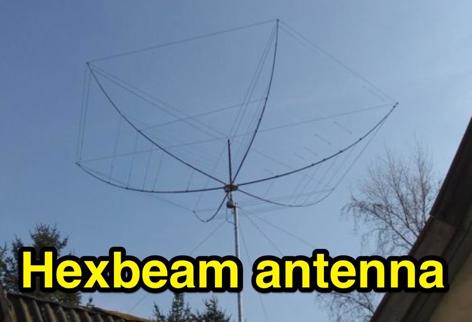 An HexBeam antenna project, a 2 full elements on six bands
 -
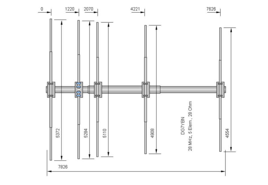 A 5 element yagi beam antenna for ten meters band with full dimentsions, eznec file and coax match informations for 50 ohms feed line
 -
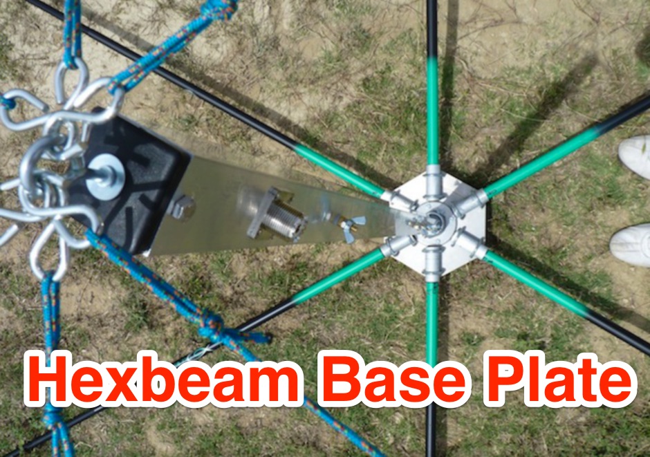 A 10mm thick aluminum plate serves as the foundation for a homemade hexbeam antenna, designed to support the central mast and six radiating elements. The construction details include precise drilling for the central mast and the six fiberglass spreaders, ensuring proper alignment and mechanical integrity. The author, FY8PE, shares insights from his experience, emphasizing the importance of robust materials for long-term outdoor deployment. The design incorporates a specific arrangement for the spreader attachment points, allowing for easy assembly and maintenance of the hexbeam's unique geometry. While specific performance measurements are not detailed, the focus on structural strength and material choice suggests an emphasis on reliability in various weather conditions. The project provides practical guidance for hams looking to build a durable hexbeam base.
 -
 Spider Beam antenna pictures in a youtube video
 -
 The broad band hexagonal beam (hexbeam) designed by G3TXQ and built by K4KIO
 -
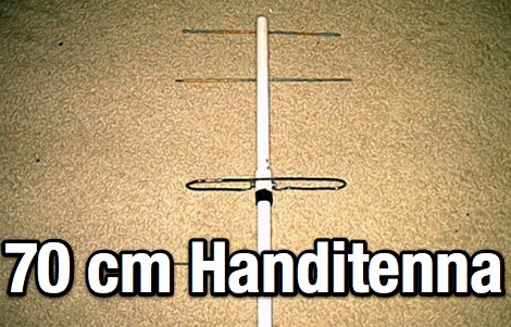 A homemade 70cm handitenna made with a PVC pipe
 -
 Ten essential tips and truisms for understanding HF antenna: Non-resonant wire dipole antennas fed with open-wire line and an antenna tuner can function effectively as multiband antennas, as detailed in "The Classic Multiband Dipole Antenna" by WB8IMY in March 2004 QST. Coaxial cable, unlike balanced parallel-wire feed lines, can cause RF to travel on the outer shield braid, leading to RF feedback to the station; a 1:1 balun at the dipole center can mitigate this by isolating the unbalanced coaxial feed line. Antenna gain is achieved by shaping and directing RF energy, with beam antennas concentrating power in a specific direction, and wire antennas also exhibiting shaped radiation patterns. An antenna tuner's primary role is to match the transceiver's 50-ohm output to the antenna system's impedance, allowing modern transceivers to deliver full power. Wire antennas do not always require center feeding; end-fed long wires or off-center-fed dipoles (like the Windom) can be used, though they often necessitate an antenna tuner and a counterpoise or radial network. Dipole antennas do not need to be perfectly horizontal; their legs can be bent or inclined, which affects feed point impedance and may require SWR experimentation with coaxial feed. Vertical antennas shorter than a half wavelength require an efficient ground system, typically comprising elevated or buried radial wires, with more radials generally leading to better efficiency. A 1:1 SWR indicates an impedance match but does not guarantee antenna efficiency; an inefficient vertical antenna with a poor ground system can show a low SWR while wasting most RF as heat. Investing in high-quality, low-loss feed line, especially coaxial cable, is crucial for maximizing RF signal transfer and overall antenna system performance.
 -
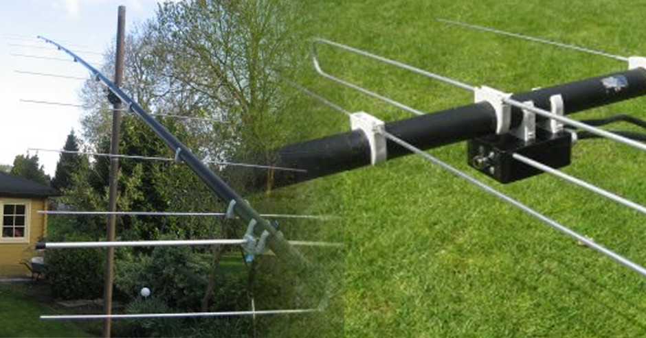 A ten element ultra-lightweight yagi beam antenna for 144 MHz based on YU7EF design concept
 -
 G/T (Gain-to-Noise Temperature) is a critical figure of merit for evaluating the receive performance of VHF/UHF antennas, particularly for weak-signal work like EME (Earth-Moon-Earth) or meteor scatter. This resource presents extensive simulation data for numerous 2-meter and 6-meter Yagi antenna designs, originally compiled by _VE7BQH_ (Lance Johnson). The lists, updated as of October 2017, include various antenna models from designers such as _DK7ZB_, G0KSC, and K1FO, providing key performance parameters. Each entry details the antenna's G/T value, gain, front-to-back ratio, beamwidth, and VSWR at specific frequencies like 144.1 MHz or 145.0 MHz. The data facilitates comparison of different Yagi configurations, including those with folded dipoles and varying intrinsic impedances, aiding radio amateurs in selecting optimal antennas for their specific operational needs on the 2-meter and 6-meter bands.
 -
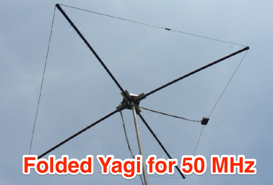 50MHz Collapsible 2 Element Mini Beam antenna, an overview the development of the 6MBA.
 -
 A multiband HF Vee Beam antenna at VK5SW. If you're lucky enough to have the room, perhaps you may like to put up a multiband Vee Beam antenna for the HF bands.
 -

-
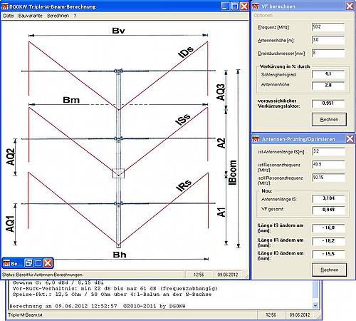 The Triple-M-beam calculation program is used for the calculation of Triple-M-beam antennas by DG0KW
 -
 The 60-page PDF document, "Antenna Systems and Theory For The Non-Technical Ham" by Jim Abercrombie, N4JA, provides a foundational understanding of antenna systems. It explains basic antenna theory, including how antennas work, electromagnetic wave polarization, and the role of frequency. The resource details various antenna types such as flat top dipoles, inverted-V dipoles, shortened loaded dipoles, G5RV dipoles, Carolina Windoms, and end-fed configurations. Vertical antennas, including ground-mounted trapped verticals and inverted-L verticals, are also covered. Directional beam antennas like monoband Yagis, cubical quads, and log-periodic arrays are discussed. Propagation modes, including ground-wave, direct wave, and skywave propagation, are explained in detail, with specific attention to the D, E, and F layers of the ionosphere and their effects on HF communication. Technical concepts such as standing wave ratio, decibels, resistance, and reactance are defined, along with calculations for half-wave resonant dipole lengths. The document addresses feed-line radiation, balun applications, and critical antenna and tower safety considerations. It aims to dispel common antenna myths and educate hams on making informed antenna choices.
 -
-
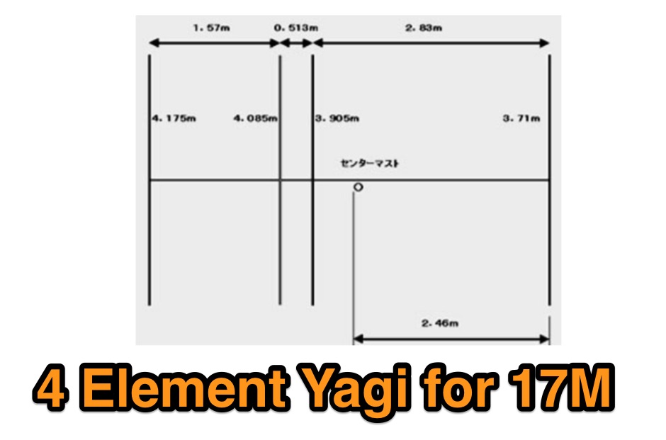 A 4 element yagi beam antenna for the 17 meters band with pictures and element dimension and spacing
 -
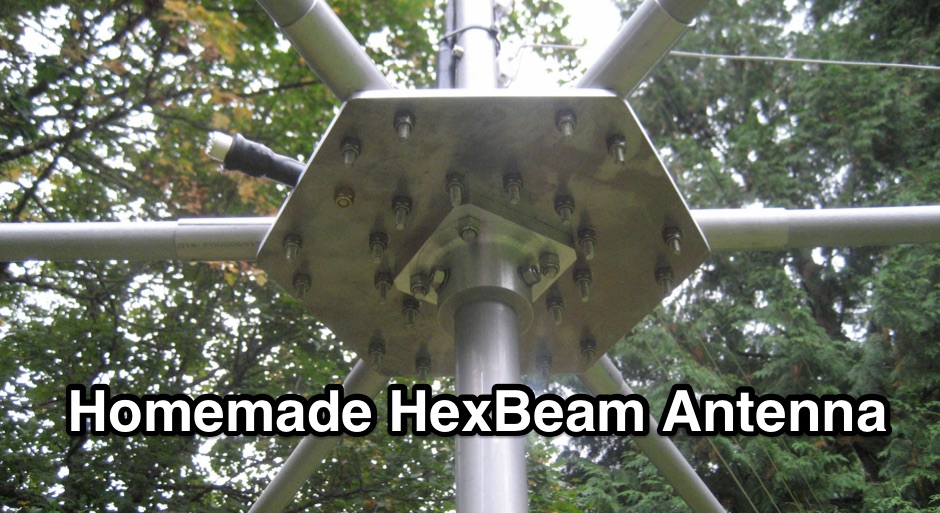 A long picture gallery of a homebrew hexbeam antenna project
 -
 Radio New Zealand International is a Shortwave Broadcaster. Our broadcasts are beamed to the island nations of the Pacific but can also be heard in other parts of the world.
 -
 This resource details the construction of a Moxon rectangle antenna, a two-element wire beam, drawing inspiration from a _QST_ article by Allen Baker, KG4JJH, and a project group led by KD6WD. It outlines the use of _AC6LA_ software for critical measurements (A-E) to design the antenna for specific bands like 17 meters, emphasizing the simplicity of adjusting frequency and wire size. The guide covers material selection for spreaders, such as telescoping fiberglass fishing poles, and various hub constructions, including aluminum tubing and PVC joints, with accompanying images. The author shares practical insights from building multiple Moxons for 10, 15, 17, and 20 meters, noting consistent 1:1 SWR at design frequencies and broadbanded performance. It describes the feedpoint assembly using a 1:1 Yagi current balun and wire nuts for robust, adjustable connections. The resource also discusses element insulators made from Lucite strips and attachment methods to spreaders using plastic wire ties and duct tape, ensuring precise element spacing. Performance observations include significant signal improvements (4-5 S units) over quad loops and a unique "DX-Vane" effect where the suspended antenna self-aligns with the strongest DX signal. The author also recounts an unsuccessful attempt at a dual-band 17/20 meter Moxon, concluding that the Moxon is inherently a monoband antenna, supported by _EZNEC_ plots for a 17-meter design.
 -
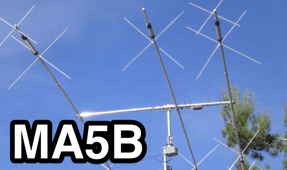 Cushcraft MA5B 20 / 17 / 15 / 12 / 10 Meter Beam Antenna assembly and installation manual
 -
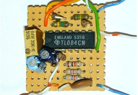 A sweep generator that produces a sawtooth waveform which sweeps the oscilloscope beam from left to right via its X input, and simultaneously the VCO frequency.
 -
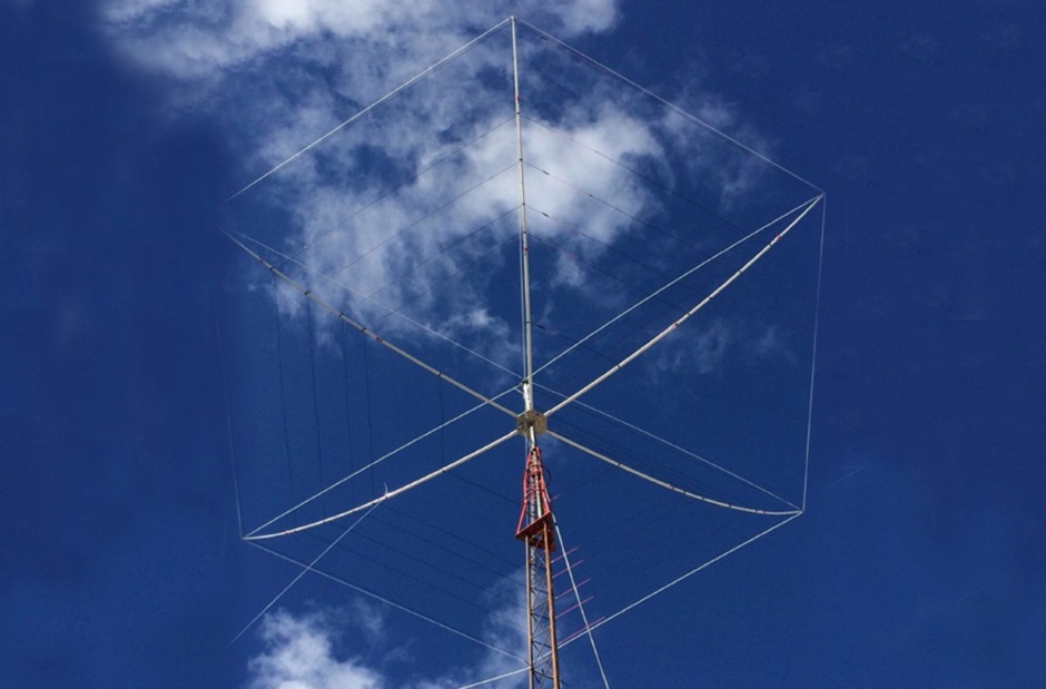 Spanish HexBeam antenna manufacturer, produce antennas kits, and part for HexBeam antennas
 -
 MW0JZE Manufacturer of the G3TXQ Broadband Hexagonal Beam - HexBeam Antennas
 -
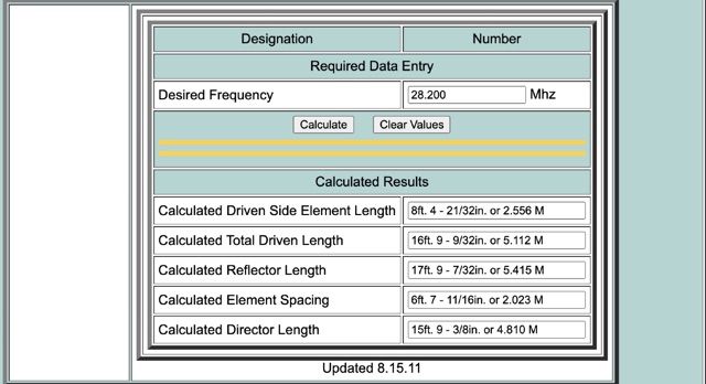 This calculator is designed to give the critical information of a particular beam antenna, in this case a three element Yagi, for the frequency chosen.
 -

-
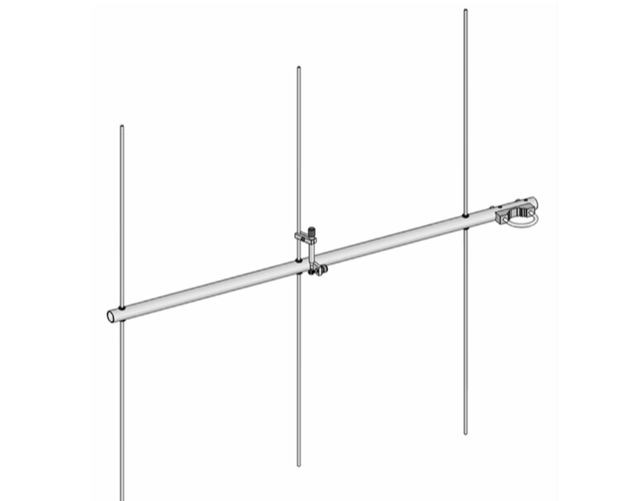 HF Beam Calculator for Amateur Radio and CB Communications
 -
 A 2x3-foot laminated world map product is detailed, offering customization for amateur radio operators. Each map features two distinct views: one centered on the operator's specific station location and another precisely centered on its _antipode_. Countries are clearly labeled, complemented by a tabular listing of all countries. The map integrates a standard latitude/longitude grid alongside concentric circles that delineate distance increments radiating outward from the operator's QTH. Personalization includes the operator's name, callsign, and location printed directly on the map. This custom mapping service provides a unique visual aid for DXing and propagation analysis, allowing operators to quickly ascertain beam headings and distances from their station. The dual-view presentation, particularly the antipodal centering, offers a practical reference for understanding long-path propagation and identifying potential DX opportunities. The inclusion of distance circles and personalized station data makes it a tailored tool for daily operating and contest planning, distinct from generic world maps.
 -
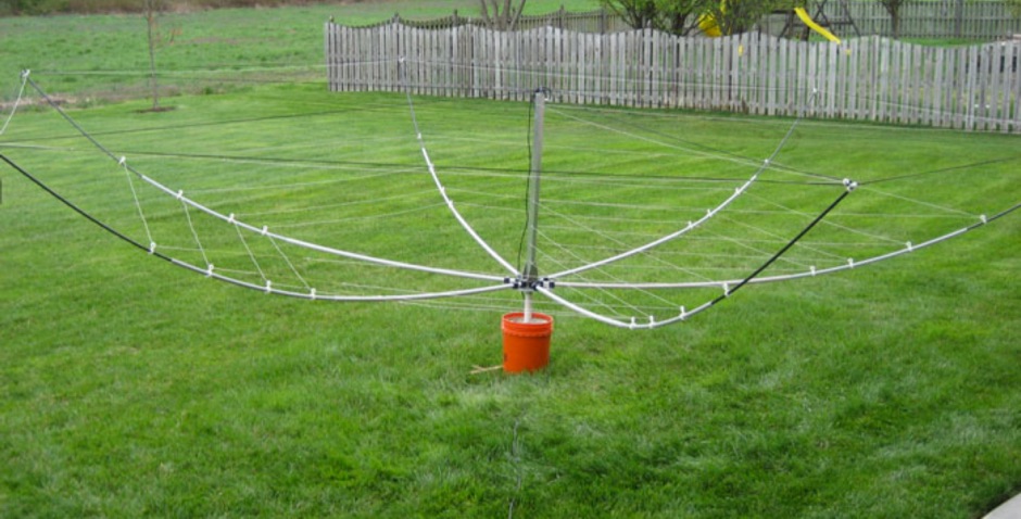 This version of the broadband hexbeam is based on the work of Hunt G3TXQ, HB9MCZ, and Shoemaker K4KIO. EZNEC model is based on a wider element spacing than the version published in QST by K4KIO