Search results
Query: 10m coax antenna
Links: 19 | Categories: 0
-
 Details the construction of a J-vertical antenna specifically for the 10-meter band, offering a practical alternative to a _Slim Jim_ design for 28 MHz. The resource outlines the use of aluminum tubing for the half-wave vertical section and coaxial cable for the quarter-wave matching section, providing specific calculations for element lengths based on frequency and coaxial cable velocity factor. It contrasts the performance of the J-vertical with center-fed dipoles and end-fed verticals, noting superior results in previous comparisons. The article further presents a more recent iteration of the J-vertical, constructed using a fiberglass pole and insulated wire, with updated dimensions for 28.8 MHz. It includes practical advice on weatherproofing connections and securing the antenna for durability against adverse conditions, referencing the survival of an original _J Vertical_ during 110 MPH winds in 1987. The SWR performance is reported as 1.1:1 at 28.6 MHz, maintaining below 1.5:1 across 28.3 to 29 MHz.
 -
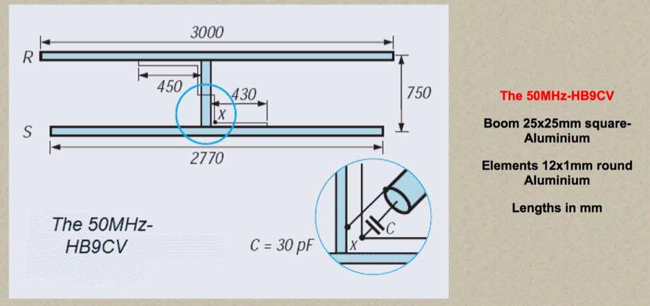 The HB9CV-Beam is a 2-Element-Yagi with two driven elements and was introduced by Rudolf Baumgartner, HB9CV in the 1950ies. This beam antenna is a coax-feeded version of the ZL-Special construction by DK7ZB for 2m, 6m and 10m
 -
 The Flower Pot Antenna project details a portable dual-band antenna primarily operating on 10 meters, with secondary resonance near the 30-meter band. Construction involves winding RG58 coaxial cable uniformly around a large plastic flower pot, approximately 70cm high with a 60cm top diameter. The design eliminates the need for radials, contributing to its compact and lightweight nature. Key construction steps include soldering the inner conductor to the shield at one end of the wound cable and connecting the wound cable's shield to the rig cable's inner conductor at the base. An LC network, comprising a variable capacitor (0-200pF) and an inductor (10 coils, 5cm diameter, 2mm wire), is inserted between the wound cable's inner conductor and the rig cable's shield. Tuning is performed with an antenna analyzer, adjusting cable length and the variable capacitor for optimal impedance on 10 meters. The antenna performs effectively when installed horizontally.
 -
 manufactures and distributes HF, VHF, UHF and SHF equipment covering 10MHz. - 47.0GHz. Our products include: Wireless LAN / WAN Bidirectional Linear Amplifiers, Low Noise Preamplifiers - LNA's, RF Linear Amplifiers, Relays, Transverter Systems, Frequency Translation Systems, Downconverters, Antennas, Parabolic Dishes, Coaxial Cable, Relays, Antenna Switches, Microwave Test equipment, PC controlled Receivers, Microwave Linear Amplifiers including models for Telemetry, Wireless, and CDMA applications.
 -
 Demonstrates the construction and performance of an updated ZS6BKW multiband dipole, a variant of the _G5RV_ antenna, specifically designed for HF operation. The article details a real-world installation using 13.5m copper wire elements and 12.2m of 450 Ohm ladder line, configured as a sloping inverted-V with the apex at 10m and ends at 4m above ground. It covers the critical aspect of impedance matching, incorporating an 8-turn choke balun at the feedline transition to RG-58U coax to mitigate RF common mode current. Measurements confirm favorable SWR readings below **1.3:1** on 7.1 MHz, 14.11 MHz, 18.06 MHz, and 24.8 MHz, indicating effective resonance across 40m, 20m, 17m, and 12m bands. The installation also shows usable SWR dips on 3.55 MHz (5:1), 29.02 MHz (2:1), and 50.84 MHz (3:1), extending its utility to 80m, 10m, and 6m with an antenna tuning unit. Initial on-air results report clear reception of stations over **5000km** away, validating its DX potential.
 -
 Constructing an HF End-Fed Half-Wave (EFHW) vertical antenna, the resource details the winding of a monoband matching unit, inspired by _AA5TB_, designed to provide a 50 Ohm impedance match without a ground plane or antenna tuner. It specifies the use of a _T200-2_ ferrite core for the transformer, outlining the 13-turn secondary and 2-turn primary winding process with enamelled copper wire. The document also describes the integration of a coax capacitor, whose length is critical for tuning and varies by band, with specific starting lengths provided for 20m, 17m, 15m, 12m, and 10m operation. The practical application section guides the builder through tuning the antenna using an antenna analyzer, emphasizing the iterative process of spacing secondary windings and trimming the coax capacitor to achieve resonance at the desired band frequency. It highlights the antenna's low angle of radiation, beneficial for DX, and claims up to 2 S-points improvement over a _G5RV_ or similar doublet when used as an omnidirectional vertical. A comprehensive shopping list, including specific part numbers from _Rapid Electronics_, is provided, along with advice on selecting fiberglass fishing poles for support and suitable antenna wire.
 -
 The 6 Band Inverted L Antenna MK3 is a versatile multiband antenna designed for amateur radio operators. This antenna covers 160m, 80m, 40m, 20m, 15m, and 10m bands, making it suitable for a wide range of HF communications. The design is based on a W3DZZ configuration, incorporating traps for optimal performance. The MK3 version features a sturdy 5/8th CB mast, replacing the original timber mast, which enhances durability against harsh weather conditions. The antenna's construction allows for effective operation, particularly on the 40m band, where it has been successfully used to contact distant locations including ZL, VK, and Antarctica. Constructing this antenna requires careful attention to detail, especially regarding the radials and grounding. The traps resonate at specific frequencies, and additional resources are available for building coaxial traps. The antenna is designed to work efficiently without an ATU on the lower bands, while higher bands may require tuning. This project is ideal for both beginner and intermediate operators looking to enhance their station with a reliable multiband antenna.
 -
 The ZS6BKW wire antenna, a variant of the G5RV, utilizes a specific 13m (42.6 ft) length of 450-ohm window line as its matching section, feeding a 28.5m (93.5 ft) flat-top element. This design aims for lower SWR on 40m, 20m, 17m, 12m, and 10m compared to a standard G5RV, often achieving SWR values below 1.5:1 on these bands without an antenna tuner. The feedpoint impedance transformation provided by the window line allows for direct connection to 50-ohm coax on multiple bands. F4FHH's experience involved constructing the ZS6BKW and evaluating its performance against an _OCF dipole_ (Off-Center Fed) on various HF frequencies. The article includes observations on SWR readings and operational effectiveness, highlighting the ZS6BKW's suitability for multi-band operation. The antenna's overall length, including the flat-top and window line, is approximately **41.5 meters** (136 feet), making it a significant wire antenna for fixed station use. Comparative analysis with the OCF dipole provided practical insights into the ZS6BKW's advantages and limitations, particularly concerning bandwidth and tuner requirements.
 -
 Demonstrates the design and construction of a compact, portable multi-band mini-delta loop antenna, specifically optimized for /P (portable) operations from remote locations like Scottish islands. The resource covers the theoretical underpinnings of half-wave loops, contrasting closed and open configurations, and then details the application of a folded dipole principle to achieve a 50-ohm match for direct coax feed. It presents empirical formulas for calculating element lengths, considering the velocity factor of common wire types, and provides a detailed example for a 20m (14.175 MHz) version. The article includes a comprehensive table of dimensions and allowances for a five-band (20m, 17m, 15m, 12m, 10m) mini-delta beam, along with construction hints for the central support and balun. It specifies a 1:1 trifilar balun wound on a ferrite rod and describes the antenna adjustment process using an _MFJ-259B Antenna Analyser_. Initial test results indicate an SWR of 1:1 at resonance and a bandwidth of approximately 240 kHz on 20m, even at a low height of five feet above ground. The distinctive utility lies in its focus on a practical, easily deployable beam antenna for portable DXing, offering a viable alternative to more complex or larger arrays.
 -
 Accurately determining an antenna's feedpoint impedance is crucial for optimal performance, especially when experimenting with new designs or making adjustments. While SWR meters provide basic information, a full complex impedance measurement reveals the resistive and reactive components, which are essential for proper matching. Modern antenna analyzers, like the _Palstar ZM30_ or MFJ259B, simplify this task, but measurements taken through a transmission line require careful interpretation due to impedance transformation. This resource details a calibration method to precisely account for the effects of the feedline. It explains how a transmission line can significantly alter the measured impedance, illustrating this phenomenon with a Smith Chart example where an 80m antenna's [22 + j6] Ohms feedpoint impedance transforms to [82 + j45] Ohms after a 10m line. The guide demonstrates using a transmission line calculator applet, such as the one by W9CF, to reverse this transformation. It outlines the process of calibrating a specific length of RG174 coax, showing how an initial 26ft estimate was refined to **25.85ft** to accurately predict a known 22 Ohm load, significantly improving accuracy over uncalibrated results.
 -
 A loop antenna made with common RG-213 coax and rests on a cross made of 6 mm fibreglass rods anf a 6.5- 30MHz tune
 -
 Optimizing a G5RV or ZS6BKW multiband wire antenna for HF operation often involves addressing common SWR issues and understanding feedline characteristics. This resource chronicles the construction and performance evaluation of a G5RV, initially built for 80m, 40m, 15m, and 10m bands, by a newly licensed Foundation operator. The author details the selection of materials, including 3.5 mm stainless steel wire for the doublet arms and enameled copper wire for the open-wire feeder, and the initial decision to omit a balun based on common online information. The narrative highlights the initial disappointing performance, characterized by high receive noise and poor signal reports on 80 meters, despite the transceiver's internal ATU achieving a 1:1 match. This led to experimentation with a coax current balun and further research into G5RV myths, such as SWR claims and the necessity of a balun. The author then describes modifying the antenna to the ZS6BKW configuration, which involves specific changes to the doublet and feedline lengths, and integrating a 1:1 current balun wound on a ferrite toroid. The modifications resulted in improved reception and transmit performance across the bands.
 -
 The X80 multi-band HF vertical antenna, a commercial iteration of the Rybakov design, exhibits a physical length of 5.5 meters, or approximately 18 feet, and is constructed from aluminum tubing. It operates as a non-resonant vertical, requiring an external antenna tuner for impedance matching across its intended operating frequencies. The antenna's design incorporates a 1:4 UNUN at its base, facilitating a nominal 50-ohm feed point impedance for the coaxial cable. Performance observations indicate effective operation on 40 meters, 20 meters, 15 meters, and 10 meters, with reduced efficiency on 80 meters and 160 meters due to its relatively short electrical length for these lower bands. Comparative analysis with a G5RV dipole and a half-wave end-fed antenna reveals the X80 offers a lower take-off angle, beneficial for DX contacts, particularly on the higher HF bands. Field tests conducted with an Icom IC-706MKIIG transceiver and an LDG AT-100ProII autotuner demonstrate the X80's ability to achieve acceptable SWR across 80m through 10m. The antenna's compact footprint and ease of deployment make it suitable for restricted spaces or portable operations, though its performance on 80 meters is noted as a compromise compared to full-size resonant antennas.
 -
 Constructing an End-Fed Half-Wave (EFHW) antenna offers a practical solution for HF operators seeking a multiband wire antenna without the need for extensive radial systems. This design typically employs a high-impedance transformer at the feed point, matching the antenna's inherent high impedance to a 50-ohm coaxial feedline. The article specifically details a 2012 approach, focusing on a transformer with a 49:1 turns ratio, which is a common configuration for EFHW antennas. The resource outlines the construction of a wire element cut for a half-wavelength on the lowest desired band, with specific coil arrangements enabling operation on harmonically related bands such as 40m, 20m, and 10m. It discusses the physical dimensions and winding details for the matching transformer, often utilizing a ferrite toroid core to achieve the necessary impedance transformation. The content provides insights into the operational principles and practical considerations for deploying such an antenna, including methods for tuning and optimizing performance across multiple amateur radio bands. While acknowledging that the presented information from 2012 may be superseded by newer insights, it serves as a foundational reference for understanding EFHW antenna theory and construction.
 -
 A 60-foot available space, for example, might necessitate a shortened multiband dipole array to cover 80, 40, and 15 meters effectively. This resource details the construction of such an antenna, combining full-size and coil-loaded dipoles on a single feedline. It addresses the common challenge of fitting multiple HF bands into restricted physical footprints, providing practical guidance for hams with smaller backyards or portable operations. The core of the offering is an interactive calculator that determines required loading coil inductance and dipole lengths for various amateur bands from 160m to 10m. Users input their available space, and the tool provides dimensions, coil turns, and an efficiency rating (Good or Fair) based on the antenna's electrical length relative to a quarter-wavelength. It also suggests suitable _PVC_ pipe diameters for coil forms. The article further illustrates a center feed-point assembly using an 18-inch section of 2-inch _PVC_ pipe, detailing eye-bolt spacing and coaxial connector installation. It emphasizes the importance of adequate spacing between parallel dipoles and offers customization options for the feed-point, including the addition of a _Balun_ for improved feedline isolation.
 -
 This article describes the construction of a simple dual-band VHF/UHF end-fed vertical dipole antenna designed for local repeater access using an Icom IC-705 radio. Built from a single piece of RG58U coaxial cable, the antenna consists of a 460mm exposed inner conductor, 450mm of intact coax, and a 9-turn choke balun wound on a 27mm former. Mounted on a 10m Spiderpole, the antenna achieves excellent SWR readings (<1.2:1 on 2m, <1.5:1 on 70cm) and provides effective coverage of local repeaters with unexpected reach into distant locations.
 -
 A 10-meter half-wave vertical antenna, designed by Thomas 4L/G8BAG, offers a practical solution for hams with limited space and materials. This "flower pot" design utilizes common hardware store items such as 60mm plastic drain pipes and 75 Ohm coax cable, demonstrating that effective HF operation doesn't require specialized components. The author details the coax preparation, including stripping the outer sleeve and braid at specific measurements like **2510 mm** and 2450 mm, and integrating it into the pipe structure. The construction emphasizes simplicity and low cost, providing an accessible path to getting on the air on the 10m band, especially when a horizontal beam is not feasible. The article notes an SWR of _1.5:1_ with 75 Ohm coax, managed by an MFJ 258 for impedance matching. This temporary solution proved robust, withstanding various weather conditions and achieving contacts across continents, including W, VK, BG, G, JA, and VR2, using 100W SSB from Georgia.
 -
 The author explores enhancing the performance of a 7-meter fiberglass squid pole wire antenna for amateur radio. The wire, resonant at 10MHz, poses impedance challenges on various bands. Experimenting with direct coax feed and UN-UN transformers, the LDG Z11-Pro2 auto-tuner is found effective but may show deceptive SWR readings. The author employs adjustable UN-UN ratios and introduces a custom "porcupine" coil to optimize the antenna's efficiency.
 -
 The resource details the construction of a J-pole vertical antenna specifically engineered for motorcycle mounting, addressing the common issue of interference with top cases. It outlines the fabrication process, beginning with an aluminum angle bracket for secure attachment to the lateral support, followed by the creation of the antenna's base from an 8mm threaded rod bent into a U-shape, approximately **40mm** wide. The article specifies the precise method for coaxial cable connections using eyelets and 3mm screws, ensuring robust contact. Further construction steps involve fitting a 10mm aluminum tube onto the threaded rod, with a screw securing the radiating element and establishing core contact. The design prioritizes mechanical stability against vehicle vibrations over fine-tuning SWR with sliding collars. Initial testing yielded a _SWR_ of **1.2** across a significant portion of the band, with improvements noted by optimizing the coaxial braid contact point near the support bracket. The document provides practical insights into material selection and assembly, emphasizing durability for mobile operation. It concludes with aesthetic options, allowing the builder to paint the antenna or retain its natural aluminum finish, making it a functional and adaptable solution for UHF motorcycle communications.