Search results
Query: 40m Moxon
Links: 18 | Categories: 0
-
 SM0DTK's 40-meter Moxon antenna project details the construction and deployment of a wire Moxon rectangle, specifically dimensioned for the 7 MHz band. The resource outlines the use of a _Moxon Rectangle Generator_ for calculating wire lengths and the fabrication of plexiglass supports for corners and the feeding point. It describes the practical challenges of elevating the antenna to approximately **14 meters** using an aluminum tube and fiberglass rod, emphasizing the adjustment process for achieving the correct rectangular shape. The article presents comparative results against a 60-meter long-wire and a full-size 40-meter ground plane antenna. The Moxon demonstrated significant directional gain towards the west, facilitating DX contacts in the Caribbean with **100 watts**, while simultaneously reducing QRM from strong eastern European stations. The SWR was reported as perfect without the need for an antenna tuner, validating the design's effectiveness for targeted signal enhancement and interference mitigation.
 -
 The resource details the construction and performance of a dual-band 40/30 meter _Moxon_ antenna, evolving from an initial single-band 30-meter design that failed in a storm. It specifies materials such as four 10-meter fishing rods, galvanized iron TV antenna support pipes, 1mm diameter PVC-covered copper wire, and a piece of 75-ohm TV satellite cable for feedline. The document outlines the iterative design process, including initial resonance measurements of 9.9 MHz for 30 meters and subsequent recalculations to shift the center frequency by 300 kHz using _Moxon software_. Initial testing on a roof yielded SWR readings of 1.4:1 at 7.200 MHz and 1.5:1 at 10.280 MHz. After installation atop a 30-meter tower, the final SWR measurements were 1.1 at 7.130 MHz and 1.4 at 10.230 MHz, with a notable 30 dB front-to-back ratio on 40 meters. The 30-meter performance, while good, showed a front-to-back ratio of approximately 15 dB, suggesting a slightly high resonance. The antenna's placement on a 700-meter hill, with a significant ground drop in certain directions, is noted as a potential factor in its excellent DX performance, enabling daily contacts with the USA West Coast on 30 and 40 meters with 100 watts.
 -
 This resource presents a detailed analysis of the W6NL 2-element 40-meter **Moxon Yagi** antenna, covering its design, construction, and measured performance characteristics. It outlines key specifications such as a free-space gain of 6 dBi, 11 dBi at 70 feet, and a direct 50-ohm feed. The document highlights the antenna's physical attributes, including 52-foot elements, a 27-foot boom, and a weight of 75 pounds, engineered to withstand 125 mph winds. Modeling was performed using **AO6** and K6STI software, with a focus on the unique functions of the transverse tip elements for Moxon coupling, physical balance, efficient capacitive loading, and reduced wind load. The presentation includes comparative data, showing the Moxon's superior front-to-back (F/B) ratio and wider bandwidth compared to traditional loaded Yagis. Performance graphs illustrate the SWR, gain, and F/B across the entire 40-meter band (7.0-7.3 MHz), comparing measured results against calculated values. Azimuth and elevation patterns demonstrate high F/B, with the antenna's pattern matching that of a full-size 3-element Yagi on a 30-foot boom. It also notes a gain difference of 1.5 dB down relative to a K3LR 4-element Yagi on a 50-foot boom, providing practical benchmarks for performance evaluation.
 -
 A 40-meter reversible _Moxon rectangle_ antenna project details its construction and performance, featuring 51-foot long sides and 7.7-foot turned-in sections. The design incorporates a 16.5-foot boom, with elements spaced 1.1 feet apart, constructed from #14 covered wire. It utilizes two double-pole relays for switching between NE and SW directions, achieving F/B ratios up to 40 dB on CW and 30 dB on SSB, with distinct reflector stub settings for each mode. This antenna replaced a full-size 2-element Yagi, demonstrating comparable forward gain while offering superior F/B ratios and directional flexibility. _EZNEC_ modeling indicates only 0.2 dB less forward gain than the Yagi. The system uses no baluns, relying on half-wave feedlines and switched stubs for impedance matching. The antenna is tree-supported at 45 feet, with its effective radiation height modeled at 80 feet due to local terrain, enhancing its performance over a nearby lake.
 -
 The "Largest YU Moxon" document details the design and construction of a substantial multiband Moxon antenna, primarily for 80m, 40m, and 20m operation. It presents specific design parameters derived from NEC-based simulations, including a 4-element 80m Moxon with 37 dB F/B and 7.81 dBi gain on a 47m boom, a 4-element 40m Moxon with a bidirectional pattern, and a 6-element 20m Moxon optimized for specific side lobes. The resource provides precise element lengths and spacing in meters for each band, alongside measured SWR results across the 3.650-3.800 MHz, 7.000-7.100 MHz, and 14.000-14.350 MHz segments. The construction narrative outlines the challenges and solutions encountered by the YU team, including the use of trees for support, the creation of "ugly" air-choke baluns from RG-58 cable wound on plastic bottles for each band, and the meticulous process of attaching wires to a rope boom. It documents the physical dimensions of the vineyard site (47 x 38m) and the azimuth orientation (340 degrees) chosen for the antenna. The document is distinctively useful for its practical insights into large-scale antenna deployment in a field environment, offering real-world SWR measurements and anecdotal performance reports from CQWW contest operations. It includes numerous photographs illustrating the construction process, the team members, and the finished antenna structure, providing visual context to the technical details.
 -
 W1ZY's 40-meter **Moxon** antenna project details nine months of experimentation, culminating in a reversible array built from No. 12 insulated wire. The design incorporates two RF current baluns and a unique two-wire element construction, where each element consists of two parallel wires spaced 3 inches apart. The resource provides specific dimensions for the first prototype, including A=50.98', B=7.87', C=1.25', D=9.3', and E=18.42', optimized for 7.050 MHz CW operation. It thoroughly explains the construction of custom two-wire insulators from Plexiglas semi-rods and the critical pre-tensioning process required to maintain wire separation and array integrity. The author, Bill, emphasizes the antenna's exceptional receive performance, noting a 30-35 dB front-to-back ratio, which allows for significant signal rejection from the rear. While the Moxon offers 5-6 dB gain on transmit, its primary advantage lies in its ability to radically reduce rear-facing signals on receive, a characteristic Bill believes is often overlooked in transmit-focused comparisons. The guide details a flexible tuning method using removable tail-end jumpers, enabling adjustments to both tail-end and parallel dimensions without re-soldering the feed point, a technique refined over three prototypes.
 -
 A 7 MHz vertical half-Moxon array, designed by F6IRF, is presented with its MMANA model, featuring a 20cm gap between the two horizontal elements. The design aims for a low take-off angle, crucial for DX work, and includes specific dimensions for the driven element and reflector, which are constructed from 2mm copper wire. The antenna's feedpoint impedance is approximately 50 ohms, allowing for direct coax feed without a matching network, and it is intended for portable or temporary installations. Field results indicate the antenna provides a **3 dB** gain over a quarter-wave vertical, with a front-to-back ratio of **10 dB** on 40 meters. The author notes successful DX contacts into _VK_ and _ZL_ from France, demonstrating its effectiveness for long-haul communication. The design emphasizes simplicity and portability, making it suitable for operators seeking a directional antenna solution for the 40m band without complex setup requirements.
 -
 Illustrates the construction of a compact _Moxon_ beam antenna specifically tailored for the 40-meter band (7 MHz). The resource details a homebrew project by W7XA, emphasizing its design for limited space while maintaining good bandwidth and directivity characteristics. It highlights the practical application of the _Moxon_ rectangle model to achieve performance on a lower HF band. The primary content is a downloadable PDF document titled "40-Meter-Mini-MOXON-Beam-Antenna.pdf," which provides comprehensive illustrations and technical specifications for replicating the antenna. This includes dimensions, materials, and assembly instructions, making it a practical guide for radio amateurs interested in directional antennas for HF. The project demonstrates how a relatively small footprint can yield a directional antenna suitable for DXing or contesting on 40 meters, a band typically requiring much larger arrays for similar gain and front-to-back ratios. The documentation supports hands-on construction.
 -
 The resource provides an in-depth analysis of the W6NL 40m _Moxon Yagi_ antenna, utilizing a NEC-2 model to simulate its performance. It details the antenna's design parameters, including element lengths and spacing, and explores critical operational aspects such as feedpoint impedance, SWR across the 40-meter band, and radiation patterns. The document systematically presents the model's setup and the methodology for evaluating the antenna's behavior in different environments, including free space and over real ground. Performance data derived from the NEC-2 model illustrates the antenna's forward gain, front-to-back ratio, and beamwidth. For instance, the model predicts a free-space gain of approximately **6.5 dBi** and a front-to-back ratio exceeding **20 dB** at resonance. Comparisons are drawn between free-space performance and operation at various heights above average ground, demonstrating the impact of ground proximity on take-off angle and overall efficiency. The analysis also touches upon the antenna's bandwidth characteristics, indicating its suitability for the entire 40-meter band with acceptable SWR.
 -
 The GW3YDX Super Moxon antenna design improves upon the standard Moxon Rectangle by incorporating additional directors in a rectangular configuration, yielding enhanced directivity and gain. For the 6m version, modeling with 4NEC2 and EZNEC+ indicated a 3dB gain increase and a 26.5dB front-to-back ratio, with VSWR below 1.5:1 between 50.0 and 50.3MHz when optimized for 50.1MHz. This design achieves a narrower -3dB power point beamwidth of 60° compared to the original Moxon's 80°, contributing to better QRM rejection. The boom length for the enhanced design is just under 2m, approximately double the original Moxon's, with no increase in wingspan. Construction details include tubing lengths for 6m, 4m, and 2m versions, with specific dimensions provided for elements A through M, measured to tubing centers. For instance, the 6m version uses a 2160mm element A and a 2140mm element H. The design maintains a 50-ohm feed impedance, with practical models showing VSWR plots consistent with simulations after minor adjustments to driven element lengths. The article also references Moxgen software for initial Moxon parameter calculation and NEC/EZNEC model generation. The 2m Super Moxon version measures approximately 30" x 25", demonstrating the compact nature of the design across different VHF bands. The article highlights the antenna's performance in real-world DX contacts on 6m, achieving contacts with over 80 stations in the USA from a modest QTH.
 -
 Constructing an effective directional antenna for the 40-meter band presents unique challenges due to its physical size requirements. This resource details the homebrew construction of a 2-element _Moxon_ Yagi antenna specifically designed for 7 MHz operation. The author, TA7OM, provides a visual guide to building this antenna, showcasing the boom, element mounting, and feedpoint connections through a series of high-resolution photographs. While textual descriptions are minimal, the imagery clearly illustrates the mechanical aspects of the antenna's assembly. The _Moxon_ rectangle design offers a compact footprint compared to a full-size Yagi, making it a practical choice for many hams with limited real estate. The visual documentation allows builders to replicate the antenna's structure, including the use of PVC pipe for element support and the method for spacing the driven and reflector elements. The project emphasizes practical construction techniques for achieving a directional pattern on a challenging HF band, suitable for DXing and contesting.
 -
 The W6NL Moxon Yagi is a high-efficiency two-element 40m Yagi that uses cross elements to provide both loading and Moxon coupling, addressing the challenge of deploying a directional antenna on the 40-meter band. This resource details the transformation of a _Cushcraft XM240_ Yagi into this Moxon configuration, replacing the original loading coil LCA sections with four new assemblies. The guide provides comprehensive instructions for building the boom and elements, including specific dimensions for new sections and tee loading elements, along with detailed drawings and a full parts list for the conversion. Performance data indicates the converted antenna achieves **10.73 dBi** gain at 7.050 MHz with 99.5% efficiency and a high front-to-back ratio. The VSWR bandwidth is over **300 kHz**, ensuring good performance across a significant portion of the 40m band. Construction involves reinforcing element sections, attaching tee loading elements with U-bolts, and implementing element guying using materials like _Phillystran_ to manage sag and maintain structural integrity.
 -
 The resource examines the operational characteristics and potential of Moxon Yagi antennas, drawing insights from Les Moxon's work and subsequent NEC modeling. It presents simulated current distributions and radiation patterns for a 40-meter Moxon, comparing its performance against a standard 2-element Yagi on the same band. Specific data points include forward gain, front-to-back (F/B) ratio, and feedpoint impedance, which are critical parameters for antenna design and optimization. Further analysis extends to a 20-meter Moxon, detailing its gain, F/B ratio, and SWR bandwidth across the band. The discussion highlights the Moxon's compact footprint and its ability to achieve respectable performance metrics, making it a viable option for hams with limited space. The content provides a technical assessment of the Moxon's advantages in terms of pattern purity and impedance stability compared to other compact directional arrays. The article also touches upon the practical considerations for constructing and deploying Moxon antennas, emphasizing the trade-offs between physical size and electrical performance. It includes graphical representations of antenna currents and radiation patterns, offering visual aids to understand the theoretical concepts discussed.
 -
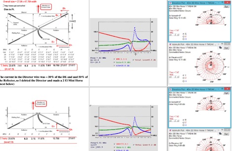 This page describes a comparison study on seven different beam antennas for 40 meters band. Yagi antennas, moxon antennas, mini horse all antennas are described with schema diagram , azimuth plot and SWR F/B Gain diagram
 -
 Constructing a directional antenna for VHF operations, particularly for 2-meter band contests or local communication, often involves balancing performance with ease of build. The Moxon rectangle, a compact two-element beam, offers a good front-to-back ratio and gain in a smaller footprint compared to a Yagi, making it suitable for portable or temporary setups where space is limited. This design typically uses a driven element and a single reflector, bent into a rectangular shape to achieve its unique radiation pattern. The article details the construction of a 2-meter Moxon antenna, specifically for 144 MHz, utilizing readily available materials like PVC pipe for the frame and copper wire for the elements. It outlines the dimensions for the driven element at 970mm and the reflector at 910mm, with a spacing of 140mm between them, and a 50mm gap at the element ends. The feedpoint is a direct 50-ohm connection, simplifying matching requirements. The project includes a parts list, a basic diagram illustrating the element layout and dimensions, and photographs of the completed antenna. The author notes the antenna's performance during a QRP contest, achieving contacts up to 100km with 5 watts, demonstrating its effectiveness for low-power VHF work.
 -
 Presents the construction and performance characteristics of the _Moxon Rectangle_ antenna, a compact, directional HF antenna design. It details the antenna's physical structure, emphasizing its robust build and ease of erection compared to traditional Yagis. The resource provides specific dimensions for building Moxons for the 10m through 40m bands, derived from _W4RNL_'s work, and discusses the critical element spacing for optimal performance. It also covers feeding the antenna with a simple choke balun and achieving a low SWR across the band. Compares the Moxon's performance to a two-element Yagi, noting its superior wind resistance and compact footprint. The author, _VK3BCY_, shares personal experiences with a 20m Moxon, reporting SWRs below 1.3 across the entire band and strong signal reports from DX stations with only 100 Watts. EZNEC Pro modeling data is included to illustrate gain and front-to-back ratios, confirming the antenna's high-performance claims. The article also briefly explores multi-band possibilities and reversible configurations.
 -
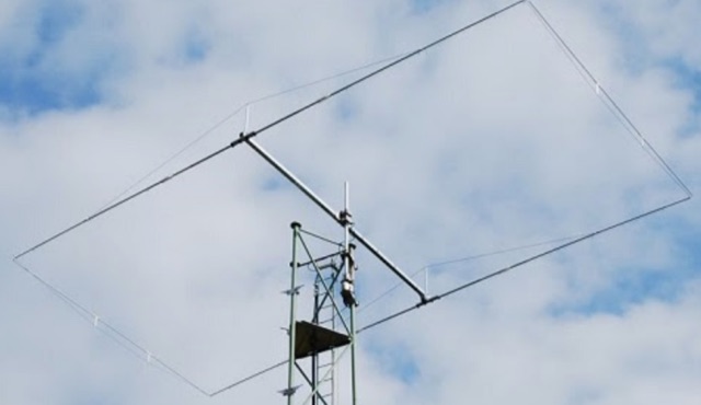 The author presents initial NEC model results for a reversible 40-meter Moxon antenna, comparing three distinct designs: a standard rectangle, a _W6NL short-tipped_ variant, and a T-hat configuration. All three models exhibit similar electrical performance, with gain figures around **5.5 dBi** and front-to-back ratios exceeding 20 dB. The primary differentiation among the designs lies in their mechanical construction and physical dimensions, which are critical for a 40-meter antenna. The rectangular Moxon requires robust support due to its element lengths, while the T-hat design offers enhanced structural integrity with slightly longer elements. The T-hat model is provisionally selected for further development, emphasizing the importance of mechanical considerations over minor electrical performance differences. Future work will focus on detailed mechanical design and construction aspects of the chosen T-hat configuration.
 -
 Optimizing directional gain on the 40-meter band often involves complex antenna designs; this resource details the construction and performance of a reversible _Moxon_ array. The design provides directional coverage from southeast to west, with a switching mechanism to reverse the pattern towards east to northwest. Key design considerations include precise element spacing, the critical role of coil inductance for proper resonance, and the use of _NEC5_ for accurate electromagnetic modeling, ensuring the antenna performs as predicted across the desired frequency range. The antenna's performance is evaluated through on-air contacts, demonstrating effective signal propagation to regions like the Caribbean, South/Central America, the US, and Europe. The article presents measured SWR plots and gain patterns, comparing them against the _NEC_ model predictions to validate the design's efficacy. Practical application notes cover mounting considerations and the benefits of its reversible pattern for targeted DXing on 40 meters, offering a robust solution for operators seeking enhanced directional capabilities without a full-sized rotating Yagi.