Search results
Query: antenna balun
Links: 160 | Categories: 2
-
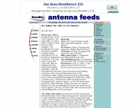
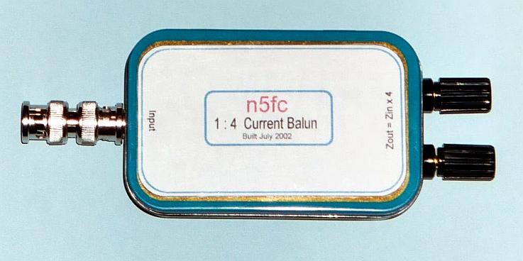
 I built a homebrew 75 meter Double Extended Zepp Antenna, And I needed a 4:1 Balun So I decided to Homebrew the Balun also. Here is how I did it!
 -
 The G5RV antenna, with an overall length of **31.10m (102ft)**, functions as a 3/2-wave on 20 meters when installed horizontally at 12m (39ft), exhibiting a resonant frequency of 14.150MHz and an approximate resistance of 80 ohms. Its 10.36m (34ft) stub line, designed as a 1/2-wave on 14.150MHz with a 0.97 velocity coefficient, acts as an impedance transformer across other bands, aiming for multiband operation without traps. On 20m and higher frequencies, the G5RV demonstrates improved gain compared to a standard dipole, attributed to the _collinear effect_ from multiple 1/2-waves along the wire. The original design sought a multiband solution for limited spaces, often requiring an Antenna Tuning Unit (ATU) for effective operation across bands like 80, 40, 30, and 20m, particularly with modern solid-state PAs. Variants, such as the F8CI modification, incorporate a 1/4 current balun at the stub line's base for symmetrical-to-asymmetrical transition, known as a _remote balun_. Proper flat-top or inverted-V installation is critical for maintaining symmetry and collinear gain, with inverted-V apex angles below 120° progressively diminishing higher-band performance.
 -
 MFJ manufacturer of ham radio antenna products, antenna tuners, antenna analyzers, morse code & CW, SWR wattmeters, antenna accessories , power supplies, audio filters, TVI filters, baluns, coax switches and more
 -
 A balun is a device that is used at the feedpoint of a balanced antenna when an unbalanced feedline is desired to feed the antenna. Balun is a contraction for BALanced to UNbalanced.
 -
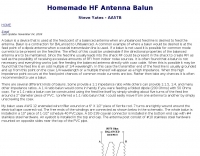
 Schema of a self made balun used to match randmon wire antennas, mainly for shortwave listening pourposes, in italian
 -
-
-
 Build a portable VHF yagi antenna for 2 meters. All you need is two rabbit ear antennas from Radio Shack, two CATV baluns, four feet of 3/4 CPVC pipe with one tee.
 -
 GM4JMU shortened dipole for 40 meters band. This article illustrates in detail how to build a resonant antenna for 7.030 MHz. Cut two 10.25-meter pieces of insulated wire, wind 40 turns of wire onto plastic tubing, and connect the wire to a central insulator using a choke balun built of RG174AU coax and a ferrite toroid. Once built, the antenna is adjusted by altering the wire length to produce the lowest Standing Wave Ratio (SWR) for best performance. The guide emphasizes careful building and adjustment for the best results.
 -
-
 Which balun to use? The hybrid balun promises advantages over both voltage and current baluns by ZS1AN
 -
 End-Fed antennas are NOT balanced systems; but neither are verticals, ground planes, discones, windoms, zepps, Marconis, half-slopers, et al. Additionally, the low-impedance antenna port of your transmitter/receiver is not balanced.
 -
 Presents a practical design for a **crossed-dipole turnstile antenna** specifically engineered for 2-meter Amateur Radio Direction Finding (ARDF) events. The author, WB6RDV, details a robust, omnidirectional, horizontally-polarized antenna, addressing the international ARDF rules requiring such characteristics at a height of two to three meters above ground. This contrasts with the vertical polarization often used in Southern California, highlighting the design's adherence to specific event requirements. The electrical design employs a classic crossed-dipole with a 75-ohm phasing section, resulting in a slight impedance mismatch and an SWR of approximately 1.3:1 with a 50-ohm feedline. Construction utilizes readily available and inexpensive PVC plumbing components and 1/8-inch bronze welding rod for elements. The guide provides step-by-step instructions for mechanical assembly, including drilling element holes at precise 90-degree spacing and preparing the RG-179 matching section. WB6RDV shares insights from his own build experience, discussing the use of plated brass versus aluminum spacers for element attachment and the effectiveness of crimping as an alternative to soldering. The document also covers final assembly, including the integration of ferrite beads as a choke balun and options for weatherproofing and alternative mounting configurations, emphasizing the adaptability of the design for other VHF bands through scaling.
 -
-

-
 The 80-meter loop antenna, measuring 86 meters (282 feet) of wire, effectively operates across 8 HF bands from 80 through 10 meters, despite its length being a compromise for specific bands. This design prioritizes a "low enough" SWR across multiple bands, aiming for lower SWR values on higher frequencies due to increased feedline losses. A 200-ohm feedpoint impedance provides a workable SWR on every band, with feedpoint impedances ranging from 100 ohms for lower bands to 300 ohms for higher bands. Radiation patterns for the 80-meter loop, mounted at 15 meters high, show a maximum gain of 7.6 dBi at a 90-degree takeoff angle on 80 meters, and up to 12.9 dBi at a 10-degree takeoff angle on 12 meters. This configuration supports regional contacts on 80 meters and provides good DX performance on higher bands. Practical construction notes emphasize using robust supports like trees, ensuring wire slack with _egg insulators_ for wind resilience, and employing an oversized 2 kW 4:1 _balun_ to safely handle higher SWR conditions, even with 100W transceivers. Feedline losses are minimized using _LMR-400_ coax or ladder line, with power transfer efficiency between 80% and 95%. Antenna simulations were performed using _xnec2c_, and the provided NEC file is compatible with other NEC2 derivatives. The antenna is tunable on 6 of 8 bands with an internal ATU and all 8 bands with an external autotuner like the LDG AT-200 Pro.
 -
 DIY Basic Electronic Theory, Basic Antenna Theory with Antennas built from common materials. What does SWR really mean. Baluns from transmission line.
 -
 This drawing shows a simple 10 meter wire J-pole antenna designed for 28.4 MHz. It is a vertical, end-fed Zepp-style antenna made from common materials and intended for easy home construction. The main radiating element is a straight length of stranded copper wire, either 14 or 18 gauge, cut to about 16.5 feet. At the top, the wire is supported by an insulator, allowing the antenna to be hoisted vertically. The matching section is made from 450-ohm ladder line, approximately 7 feet 9.5 inches long, and shorted at the bottom. This matching stub transforms the impedance so the antenna can be fed with coaxial cable. The feed point is tapped about 6 inches above the bottom of the stub, with the shield and center conductor connected at the proper points. A choke balun is formed with five turns of RG-58 coax in a 4-inch diameter loop to help reduce unwanted RF on the feed line. The drawing notes that this antenna has about 0 dBd gain, similar to a dipole, but offers an omnidirectional pattern and low-angle radiation when installed high. Its main advantage is practical performance, simple construction, and effective coverage for 10 meter operation.
 -
 Receivers, Antenna Tuners and accessories, antenna analyzers, dummy loads, wattmeters, shortwave radio receivers, baluns, filters
 -
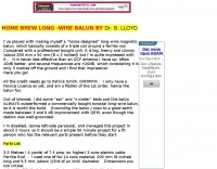
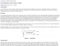 A cost effective current-mode 1:1 balun can be constructed from a length of coax and a rod typically used for a broadcast antenna loop-stick, some electrical tape, cable ties, a length of PVC water-pipe and some connectors.
 -
 The Double Bazooka Dipole is a very efficient single band antenna which is very quite, and does not require the use of a balun. This antenna consists of coax (RG58) or other 50 ohm type with the shield split at the center and the feedline attached to the open ends
 -
 Demonstrates the construction and performance of an updated ZS6BKW multiband dipole, a variant of the _G5RV_ antenna, specifically designed for HF operation. The article details a real-world installation using 13.5m copper wire elements and 12.2m of 450 Ohm ladder line, configured as a sloping inverted-V with the apex at 10m and ends at 4m above ground. It covers the critical aspect of impedance matching, incorporating an 8-turn choke balun at the feedline transition to RG-58U coax to mitigate RF common mode current. Measurements confirm favorable SWR readings below **1.3:1** on 7.1 MHz, 14.11 MHz, 18.06 MHz, and 24.8 MHz, indicating effective resonance across 40m, 20m, 17m, and 12m bands. The installation also shows usable SWR dips on 3.55 MHz (5:1), 29.02 MHz (2:1), and 50.84 MHz (3:1), extending its utility to 80m, 10m, and 6m with an antenna tuning unit. Initial on-air results report clear reception of stations over **5000km** away, validating its DX potential.
 -
 The Windom is an Off-center wire multiband Antenna. The old version was fed just by a single-wire connected on 1/3 of antenna's overall length or with an open-line feeder (later versions). Here is another model with coaxial feeder, which is compatible with Solid States - 50 Ohm output transceivers .
 -
 RFI Kit, ferrite cores, baluns, loop antennas, antenna tuners and various accessories
 -
 Selecting an appropriate antenna system for shortwave broadcasting involves evaluating various types based on performance, cost, and operational parameters. This resource details the critical specifications for broadcast antennas, including average and peak power ratings, directivity, takeoff angle (TOA), horizontal beamwidth, and gain, emphasizing that a 100-kW transmitter requires an antenna rated for 150 kW average and 400 kW peak. It clarifies that low TOA signals travel thousands of kilometers, while high TOA is for local coverage, and nearly all modern shortwave broadcast antennas are horizontally polarized. The article explores specific antenna types, such as Log-Periodic Antennas (LPAs), which offer wide frequency ranges (e.g., 2-30 MHz) and directional patterns with 11 dBi gain, costing from $20K to over $100K for multi-curtain versions. Dipole arrays, also known as curtain antennas, are prevalent in international broadcasting, featuring steerable beams (±15° and ±30°) and mode-switching capabilities to alter TOA, with high/low pairs costing over $1 million. Fan dipoles are noted for omnidirectional patterns, smaller size, and lower cost for low-power applications, while rhombics, though simple, require resistive termination and incur several dB of I2R losses. Balun considerations are crucial, as most communications baluns are not rated for the higher average and peak powers of AM broadcast transmitters. Modern shortwave antennas utilize durable materials like Alumoweld wire rope for radiators and support elements, avoiding copper, fiberglass, or materials prone to stretching or deterioration. Feeder systems for high-power stations often require tapered-line baluns to convert 50-ohm unbalanced power to 300-ohm balanced for connection to the antenna.
 -
 One common challenge in antenna systems is mitigating common-mode current on the feedline, which can distort radiation patterns and introduce RF in the shack. This project details a 1:1 balun design that ingeniously avoids traditional ferrite beads, often a costly component, by substituting them with steel wool. The steel wool, when integrated into the balun's construction, effectively attenuates unwanted RF on the outer braid of the coaxial cable, ensuring that the antenna radiates efficiently and as intended. The construction involves winding coaxial cable through a PVC former, with the steel wool strategically placed to provide the necessary common-mode impedance. This method offers a practical and economical alternative for hams looking to build effective baluns without the expense or availability issues associated with ferrite cores. The design principles focus on creating a balanced feed to the antenna, crucial for optimal performance of dipoles and other balanced radiators. Experimentation with such designs can lead to improved field results, particularly for those operating with limited budgets or seeking innovative solutions for their antenna systems. The simplicity of using readily available materials like steel wool makes this a compelling build for many radio amateurs.
 -
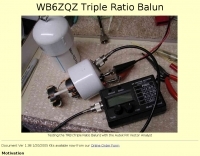 Builing a triple ration balun, that match resonant antennas from 9 ohms to 75 ohms with 1.5:1 or less SWR
 -
 A complete documentation with pictures and design of a deltaloop antenna and 1:2.5 balun
 -
 French manufacturer (F5MSU) of antennas and accessories since 1999 : Yagi, Delta-loop, dipoles, T2FD, verticales, EFHW, baluns, ununs, etc.
 -
 A 1:4 balun suitable for folded dipole antennas
 -
 Why a vertical antenna or longwire antenna might require a balun
 -
 A 40-meter reversible _Moxon rectangle_ antenna project details its construction and performance, featuring 51-foot long sides and 7.7-foot turned-in sections. The design incorporates a 16.5-foot boom, with elements spaced 1.1 feet apart, constructed from #14 covered wire. It utilizes two double-pole relays for switching between NE and SW directions, achieving F/B ratios up to 40 dB on CW and 30 dB on SSB, with distinct reflector stub settings for each mode. This antenna replaced a full-size 2-element Yagi, demonstrating comparable forward gain while offering superior F/B ratios and directional flexibility. _EZNEC_ modeling indicates only 0.2 dB less forward gain than the Yagi. The system uses no baluns, relying on half-wave feedlines and switched stubs for impedance matching. The antenna is tree-supported at 45 feet, with its effective radiation height modeled at 80 feet due to local terrain, enhancing its performance over a nearby lake.
 -
 K4TR Manufacture and sell simple dipoles, half square 2 wire phased vertical arrays, end fed zepp antennas, G5RV antennas. 1:1 baluns
 -
 This PDF document, authored by KT4QW in October 2004, details the construction and modeling of a dual-band, horizontally polarized hanging rectangular loop antenna for **10 and 17 meters**. The design, adapted from *The ARRL Handbook*, utilizes _NEC4WIN95_ software for scaling and optimization, targeting a 50 ohm feedpoint impedance. The resource includes a bill of materials, step-by-step construction instructions, and a discussion of the antenna's radiation characteristics. It presents NEC-generated elevation and azimuth patterns, comparing the loop's performance to a half-wave horizontal dipole at the same height and frequency. The 17-meter element is centered at 18.140 MHz for low SWR across the phone band, while the 10-meter element is centered at 28.500 MHz. Construction involves 14-gauge stranded copper wire and Schedule 40 PVC spreaders, with the total wire length calculated by the formula: Length in feet = 1005/MHz. The feedpoint impedance can be adjusted by modifying the rectangular aspect ratio. The document specifies hoisting the antenna to at least a half-wave above ground for testing. It notes that a balun was tested and found to have no measurable effect on SWR or radiation characteristics. A 2-meter scale model is presented to illustrate the physical design, and a "rotator" string is incorporated for directional adjustment up to 90 degrees.
 -
 The Buddipole website showcases a range of portable amateur radio antenna systems, including the **Buddipole**, Mini-Buddipole, Buddistick PRO, and BuddiHEX, designed for rapid deployment and multi-band operation from 40 meters to 2 meters. Each product page details specifications, operational modes (dipole or vertical), and compatible accessories like tripods, masts, and baluns. The site also features portable DC power management systems such as the PowerMini 2 and PowerPlus, which include integrated battery chargers and solar controllers, catering to off-grid or field day setups. Instructional videos demonstrate antenna assembly, tuning, and deployment techniques for various configurations, including the VersaTee vertical and Mini-Buddipole. Customer testimonials and DXpedition highlights, such as operations from Montserrat (VP2M) and Dominica (J38), provide real-world examples of the equipment's performance in challenging environments. The company, established in 2001, emphasizes modularity, versatility, and efficiency in its product line, all manufactured in the USA. Shipping information, a 30-day return policy with no restocking fee, and contact details for their Heber City, Utah facility are clearly presented. The site serves as a direct sales portal, offering a comprehensive catalog of antennas, power solutions, and components for portable amateur radio enthusiasts.
 -
 A multiband end-fed antenna that cover 3.5 to 30 Mhz using a 1:64 Balun based on a FT240-43 core
 -
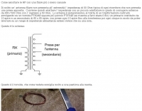
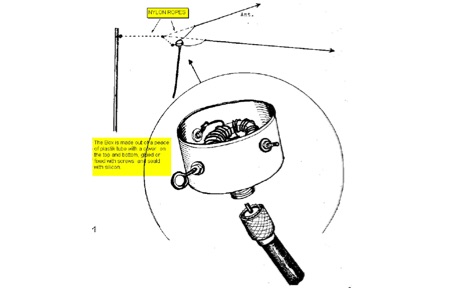
 This Magnetic Longwire Balun (MLB) makes it possible to efficiently use a coaxial lead-in cable with all forms of longwires, T-forms or other types of wire antennas, without the need for an antenna tuner.
 -
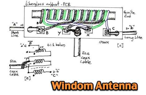 A windom multiband antenna project with pictures and diagram for the 6:1 balun
 -
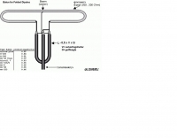
 This project is intended to aid in tuning a balanced antenna or feedline that has a high impedance 100-600 ohms
 -
 RF Choke to prevent hf currents on the feedline. This Magnetic Longwire Balun (MLB) makes it possible to efficiently use a coaxial lead-in cable with all forms of longwires, T-forms or other types of wire antennas, without the need for an antenna tuner.
 -
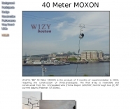 W1ZY's 40 Meter MOXON is the product of 9 months of experimentation. The final array is reversible and constructed from No. 12 insulated wire fed through two RF current baluns
 -
 The document details the optimization and construction of the _Maria Maluca_ antenna, a compact 6-band (20m-6m) directional beam. It presents a comparative analysis of shortwave antenna principles, highlighting the efficiency gains achieved by using an open feeder line and tuner as a resonant unit, contrasting this with the losses associated with traps or capacitive loads in multiband antennas. The resource specifically revisits an older South American 2-element design for 10, 15, and 20 meters, applying modern NEC-based software to develop a six-band version. Performance data is meticulously tabulated, showing impedance, free space gain, gain at 12m height, elevation angle, and front-to-back (F/B) ratio for each band from 20m through 6m. For instance, on 15m, the antenna achieves 5.1 dBd free space gain and 13.72 dB F/B ratio. The construction section provides practical guidance on element assembly using aluminum pipes and hose clamps, detailing the use of a heavy-duty glass fiber reinforced polyamide rod for electrical separation and bending strength. It also specifies the use of 450-ohm _Wireman_ line CQ 552 for the transmission line. The document includes diagrams for rod fixing, an air-wound balun, and a vertical elevation diagram for the 15m band, illustrating its DX qualification. It also discusses the antenna's suitability for portable and expedition operations, noting its compact transport dimensions (max 1.50m length, 12 lb weight) and quick assembly time (under 15 minutes). The author, Dipl.Ing. Helmut Oeller, DC6NY, is identified as a source for material kits.
 -
 Notes on homebrewing antennas by Chris G4CYA, from gamma matching, to phasing antennas, splitters and combiners, baluns and measuring techniques.
 -
 This Magnetic Longwire Balun (MLB) makes it possible to efficiently use a coaxial lead-in cable with all forms of longwires, T-forms or other types of wire antennas, without the need for an antenna tuner.
 -
 This resource details the computer-optimized design of the _ZS6BKW_ multiband dipole, an evolution of the classic _G5RV_ antenna. It begins by referencing the original 1958 RSGB Bulletin article by Louis Varney G5RV, explaining the operational principles of the G5RV's flat-top and open-wire feedline on 20m and 40m, noting its impedance transformation characteristics for valve amplifiers of that era. The article then transitions to the rationale for optimizing the design for contemporary solid-state transceivers requiring a 50 Ohm match. The core of the project involves using computer modeling to determine optimal lengths for the flat-top and matching section, aiming for a VSWR of less than 2:1 on multiple HF bands. It discusses the process of calculating feedpoint impedance based on antenna length and frequency, referencing professional literature from Professor R.W.P. King at Harvard University. The analysis also considers the characteristic impedance (Z(O)) of the open-wire line, identifying a broad peak of adequate values between 275 and 400 Ohms. Specific design parameters for the improved ZS6BKW are presented, including a shorter flat-top and a longer matching section compared to the original G5RV, with a velocity factor of 0.85 for the 300 Ohm tape. The article confirms acceptable matches on 7, 14, 18, 24, and 28 MHz bands when erected horizontally at 13m, and also discusses performance in an inverted-V configuration, noting frequency shifts. The author, Brian Austin ZS6BKW, emphasizes the antenna's suitability for modern 50 Ohm coaxial cable without a balun.
 -
 This project outlines the construction of a 3-element reversible quad antenna specifically designed for the 40-meter band. The materials required include pushup towers, pressure-treated posts, insulated wire, and various electrical components such as relays and a balun. The construction process is straightforward, beginning with the installation of the posts in a straight line, followed by the assembly of the antenna elements and their elevation to the desired height. The antenna's design allows for directional signal reception, making it ideal for operators looking to enhance their communication capabilities on the 40-meter band. The project includes detailed instructions on tuning the antenna for optimal performance, ensuring that operators can achieve the lowest SWR possible. Additionally, the design can be adapted for other bands by extrapolating dimensions, providing versatility for amateur radio enthusiasts. Overall, this reversible quad antenna project is suitable for both beginners and experienced operators, offering a practical solution for improving signal strength and directionality in 40-meter communications.
 -
 Antenna manufacturer from Poland, produce dipole wire antennas, W3DZZ FD4 Windom and long wires, baluns, dealer for toroids and connectors managed by Leszek Mlynarczyk SP1BKS
 -
 Antenna tuners, components, filters and baluns manufacturer based in germany
 -
 This is a popular antenna design as the performance is very good across the HF bands and requires little or no tuning. It is a dipole fed off center with a 4:1 current balun at the offset feedpoint. The antenna shown covers 80, 40, 20 and 10 meters with 15 meters and WARC bands
 -
 Some antenna manufacturers place baluns at the incorrect location in LPDA arrays, or tell you to route the cable incorrectly. This can cause substantial RFI and all sorts of weird problems like RF into house wiring.