Search results
Query: base loading
Links: 12 | Categories: 0
-
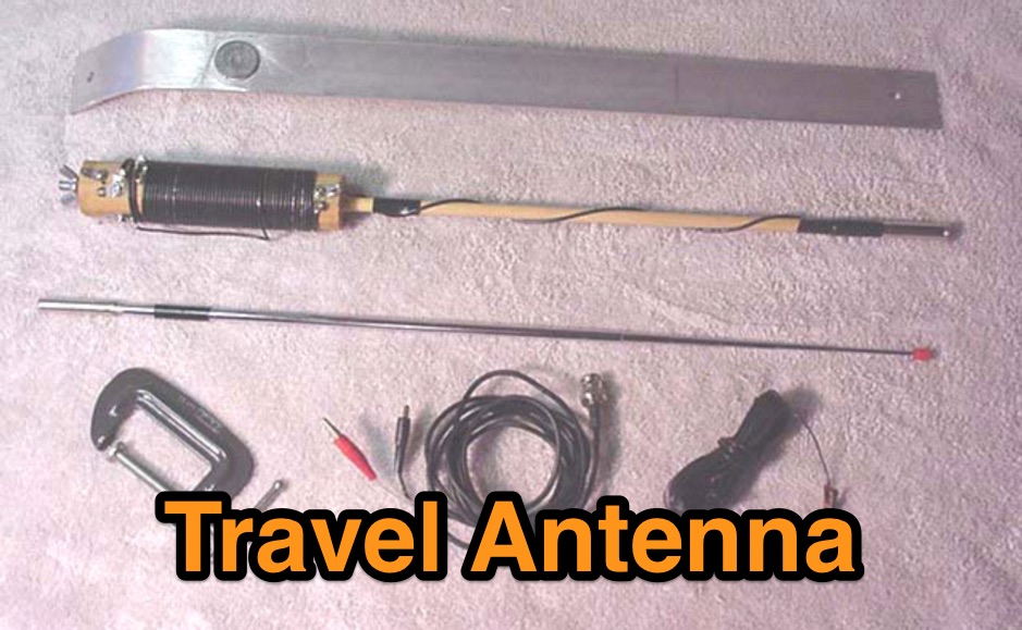 This is a low cost homebrew two band travel antenna for 20 and 40 meters. It is based on the B&W Travel Antenna concept with a telescoping whip and a loading coil
 -
 Calculations for determining the wind loading stress on an antenna mast. Link to a spreadsheet for calculating the mast bending stress based on wind speed and antenna cross sectional area.
 -
 This is a base-loaded vertical antenna that mounts on the car's roof. The loading coil is designed as a variable inductor, with a three-legged chariot that travels up and down inside the coil, with grooved brass wheels running on the coil turns, and driven by a slotted rotor tube.
 -
 A 160 meter antenna with a base loading coil used to tune the two lower frequency segments of the band.
 -
 A 40/80 meters dipole made with two loading coils based on a project by IK1ZOY
 -
 A Variable Base-Loading-Coil for use under a HF Mobile Whip
 -
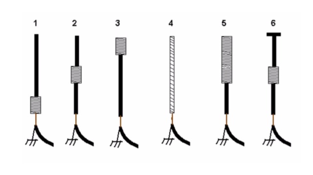 An interesting article on loading short vertical monopole antennas, representing six different methods. Base loading, Center Loading, Top Loading, Continuous loading, half and half loading and capacitive top loading.
 -
 A vertical antenna project for the 7MHz made with some spare parts. Based on a broken 20 foot fishing pole, it is based on a good ground system made with radials and a capacitive hat done to increase the global radiation resistance of the antenna. A custom loading coil is also included in this project to perfectly tune the antenna to the CW portion of the 40 meters band.
 -
 Demonstrating the construction of a short dipole antenna tailored for the 60 meter band, this resource provides detailed instructions for radio enthusiasts with limited space. The design incorporates inductive loading using two inductors (L1/L2) made from PVC tubes, allowing for effective operation on 5 MHz. The antenna consists of 12 meters of wire, divided into four sections, with specific dimensions and materials outlined for optimal performance. Results from users indicate that this antenna can significantly enhance DXing capabilities on the 60 meter band. Feedback from operators suggests that while the design is effective, adjustments may be necessary based on individual setups, such as coil diameter and wire gauge. Many users report successful construction and operation, with some experimenting with variations to improve resonance. The practical application of this antenna design has led to successful contacts and improved signal quality, making it a popular choice among 60 meter band operators.
 -
 The _G3TSO_ Mobile Antenna Page details construction and tuning methods for mobile antennas operating across **10 to 160 metres**. The content describes a Hustler-based design, optimized for RF performance and vehicle speeds, featuring centre loading. For optimal operation on various bands, the loading coil placement requires clearance from the vehicle body. Antenna resonance is critical for efficient mobile operation. A mobile antenna's base impedance may be as low as 27 ohms, requiring specific matching to achieve maximum radiation, as a minimum SWR at the transmitter does not always indicate resonance or maximum output. Tuning involves physical adjustment of antenna length to achieve resonance at the operating frequency. The _G3TSO_ page outlines a tuning procedure utilizing a low-power signal source and a field strength meter to identify maximum radiation before impedance matching. Loading coil placement, either at the base, center, or top of the antenna, influences radiation efficiency and mechanical stability for mobile installations. Centre-loaded whips, such as the Hustler design, offer a compromise between efficiency and stability, often for single-band operation. Helically wound antennas, including those for **28 MHz**, may present base impedances around 17 ohms, resulting in a 3:1 SWR at resonance. Low resistance grounding at the antenna base is also specified for optimizing performance and minimizing RFI during mobile operation. DXZone Focus: Mobile | Any | Antenna Tuning | HF
 -
 The article details the C-Pole antenna project, emphasizing its portability and ease of setup for amateur radio operators. Key features include its compact design as a vertical half-wave dipole that requires no radials, making it functional at various locations. The antenna employs capacitive loading to reduce physical length while maintaining efficiency. It includes practical advice on resonance tuning, impedance matching, and construction materials, along with a calculator for determining dimensions based on desired frequencies. Overall, it presents a user-friendly solution for portable ham radio communication.
 -
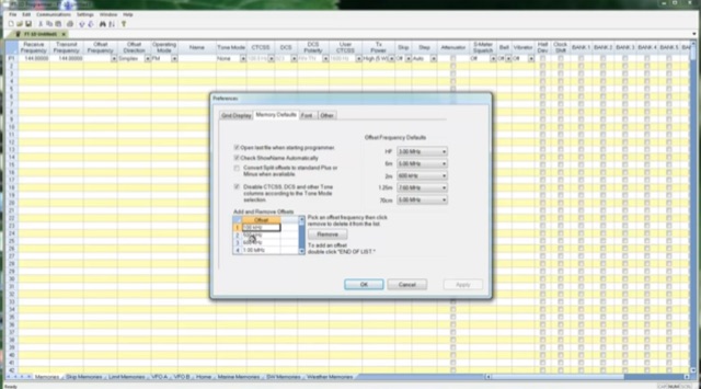 Manually programming a Yaesu FTM-100 with hundreds of channels can be very fustrating. In this article the author highlights the difficulty of entering data with small buttons and the need to look up information for each channel. To avoid this tedious process author used RT Systems software as a solution. This program simplifies programming by allowing selection based on the radio model, download of frequencies from resources like RFinder, and quick loading onto the radio. While paid unlike the free CHIRP software used previously, the author emphasizes the time saved compared to manual entry, making the cost worthwhile.