Search results
Query: crystal radio
Links: 33 | Categories: 1
-
 Circuits of SSB Transceiver, AM DSB Transmitter, Antennas, BFO, VFO, 807, FM Mike, Crystal filter and more.
 -
 Presents a crystal-controlled CW transmitter design for the 40-meter band, delivering 5 to 7.5 watts output power. The circuit innovatively employs an _IRF510_ power MOSFET in the final amplifier stage, diverging from conventional bipolar transistors. This design offers high gain, nearly 90% efficiency, and robust resistance to high SWR, allowing 30-second key-down operation into an open circuit without damage. A critical aspect is the precise adjustment of the MOSFET gate bias via a 10K trimmer pot, _R10_, to maintain quiescent current between 5 and 10 mA, preventing thermal runaway inherent to bipolar devices. The prototype was constructed on a _Radio Shack universal board_ and achieved immediate operational success. The design requires a 15-volt Zener diode to protect the MOSFET gate from overvoltage. Component sourcing information is provided, including specific crystal frequencies (7.040 MHz or 7.122 MHz) available from _Dan’s Small Parts & Kits_ or Doug Hendricks. The fixed frequency can be slightly adjusted with a trimmer capacitor. A complete bill of materials, including resistor values, capacitor types, toroid specifications, and transistor part numbers, is detailed, alongside a clear schematic diagram.
 -
 PA3FWM's software defined radio (SDR) page documents his extensive hardware and software development efforts between 2004 and 2009. Initial experiments utilized a direct conversion receiver with 90-degree phase difference, feeding a PC soundcard at 48 kHz sample rate, covering 24 kHz of spectrum around a 7080.5 kHz local oscillator. This setup, similar to AC50G's QEX 2002 article, allowed for basic I/Q signal processing to distinguish signals above and below the LO frequency. Limitations included fixed crystal frequencies, 16-bit dynamic range, and narrow bandwidth. Subsequent hardware iterations aimed for enhanced performance, incorporating external 24-bit ADCs with 192 kHz sample rates, connected via 10 Mbit/s Ethernet. A **MC145170-based PLL** and programmable octave divider provided a 58 kHz to 30 MHz tuning range. The **Tayloe mixer** was employed, with differential outputs feeding a PCM1804 ADC. An ATmega32 microcontroller handled serial data conversion to Ethernet frames, though without CRC calculation due to processing constraints. Later designs integrated AD7760 2.5 Msamples/second ADCs and a Xilinx Spartan-3 FPGA, enabling direct reception of 0-1 MHz spectrum and eventually 2.5 MHz bandwidth across the shortwave spectrum. Software was refactored to use an initial 8192 non-windowed FFT for efficient high-bandwidth processing. The project culminated in a two-way QSO on 21 MHz using the developed hardware and software, demonstrating transmit capabilities with a D/A converter. The system exhibited a 2.5 MHz wide spectrum display and a zoomed 19 kHz display, capturing signals like ionospheric chirp sounders and RTTY contest activity. Challenges included noise leakage from digital circuitry and cooling for high-power dissipation components.
 -
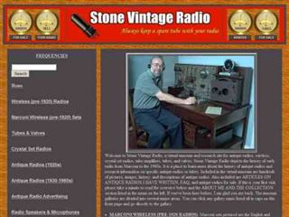 Stone vintage radio describes early radio from marconi to the 1960s. its covers antique radio, wireless, tubes, valves, crystal sets, and battery radios. included in the virtual museum are hundreds of pictures, images, and descriptions of antique radios, articles, faq, sell, and buy a radio.
 -
 Modifying the _ICOM IC-706MKII_ transceiver for out-of-band transmit capability involves specific surface-mount device (SMD) removal on the main circuit board. This procedure enables transmit functionality from 0.5 MHz to 200 MHz, excluding the commercial FM-Wide broadcast band, significantly expanding the radio's operational frequency range. The modification requires careful handling of small components and a fine-tipped, low-wattage soldering iron. Prior to beginning, all programmed memories and initial setup configurations must be noted, as the modification process will erase them. The instructions detail the necessary tools, preparation steps, and the precise location of the two SMD diodes to be removed. These diodes are situated near an oblong crystal can and a test point labeled _CP3_ on the main board. Successful completion returns the unit to its default configuration, necessitating manual reprogramming of memory channels and initial settings. This project is suitable for operators with experience in SMD work and fine soldering.
 -
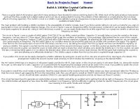 Restoring vintage amateur radio gear often presents challenges with accurate dial calibration due to the non-linear characteristics of analog tuning capacitors. This resource details the construction of a 100 kHz crystal calibrator, a crucial tool for precisely setting the frequency of older rigs lacking digital readouts. The design cleverly circumvents the scarcity and cost of 100 kHz crystals by utilizing a readily available 8 MHz microprocessor crystal, such as a _HC49U_ type, in conjunction with common _CMOS ICs_ like the 74HCT00 quad NAND gate and 74HCT393 dual 4-bit binary ripple counter. The circuit employs a two-stage frequency division process: the 8 MHz crystal oscillator output is first divided by 16 to yield 500 kHz, then further divided by 5 to achieve the desired 100 kHz output. A 5.1-volt Zener diode, _1N4733A_, regulates the power supply for the HCT series logic. The article also provides a modification to produce a 50 kHz calibrator by altering the counter reset logic. Installation involves feeding the output to the receiver front end, ensuring it's post-TR relay to prevent RF damage, and incorporating an ON/OFF switch for the 12V supply line.
 -
 Wholesale distributor of CB radios, parts, antennas, microphones, power supplies, crystals, echo boards, expanders, meters and CB accessories.
 -
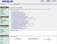 Supplier of custom designed, high performance quartz crystal filters for communications receivers and transceivers, for Yaesu Icom Kenwood and Collins radios
 -
 Details Guglielmo Marconi's foundational contributions to radio communication, highlighting his 1898 Patent **7777** which introduced tuning circuits for independent simultaneous communications. Chronicles the historic transatlantic reception of the Morse code letter 'S' on December 12, 1901, from Poldhu, Cornwall, to St. John's, Newfoundland, a distance of over _3,500 kilometers_. The exhibit showcases early Marconi 10-inch spark transmitters, identical to those used on the _Titanic_, alongside Canadian Marconi crystal detector models. It also features high-end commercial receivers like the IP501, weighing **87 pounds** and originally priced at $595.00, demonstrating the robust construction and technological advancements of the era.
 -
 Your source for weather radios, communication headsets, 14 channel radios, M&M groovy radios, smithsonian crystal radio and weather station kits, line restrictors, antennas,ham radio accessories, and battery products.
 -
 Roger, G3XBM, shares his extensive experience in **QRP** (low-power) amateur radio operation, detailing various aspects of transmitting with minimal power. The resource provides insights into VLF (Very Low Frequency) reception techniques and the construction of simple **crystal radio sets**, reflecting a foundational approach to radio experimentation. It includes links to external resources covering QRP clubs, online receivers, manufacturers, and technical references, offering a curated collection for enthusiasts. His page serves as a hub for those interested in the challenges and rewards of QRP, often comparing the efficacy of different low-power setups. The practical application extends to understanding basic radio principles through hands-on projects like crystal sets, which G3XBM has explored. The collected links provide a starting point for further research into specific QRP equipment or operating practices, drawing on G3XBM's long-standing engagement with the QRP community.
 -
 Presents a QRP AM/CW transmitter project specifically designed for the 10-meter band, utilizing a crystal oscillator and a collector-modulated AM oscillator. The design employs a 2N2219(A) transistor in a Colpitts configuration, generating 100 to 350 mW of RF output power depending on the 9-18 Volt supply voltage and modulation depth. Frequency stability is maintained by a 28 MHz crystal, with fine-tuning possible via a Ct1 trimmer capacitor for approximately 1 kHz adjustment. The resource details the RF oscillator stage, implemented with a 2N2219 NPN transistor, emphasizing frequency stability and low power dissipation. It also covers the amplitude modulation stage, managed by a 2N2905 PNP transistor, which impresses audio information onto the carrier. Selective components (C3, C4, C7, C5) enhance voice frequencies within a +/- 5 kHz bandwidth, and modulation depth is controlled by R2 and R3. The project includes a 3-element L-type narrow bandpass filter (Ct3, L3, C10) to suppress harmonics and ensure a clean output signal. The project provides a complete schematic diagram, a comprehensive parts list including specific capacitor, resistor, and inductor values, and construction notes for the coils (L1, L2, L3). It also offers practical advice on enclosure requirements, suggesting an all-metal case or a PVC box with graphite paint for RF shielding. Operational parameters such as current draw (27mA@9V to 45mA@16V) and input impedance (50 Ohms) are specified, alongside guidance on antenna matching and the importance of a valid amateur radio license for 10-meter band operation.
 -
 Sherwood Engineering Inc. (SEI) offers a repository of technical presentations and white papers focused on optimizing amateur radio transceiver and receiver performance. Content includes detailed analyses of _roofing filters_, transmitted IMD, and receiver characteristics, with specific discussions on products like the Drake R-4C and Icom IC-781. Presentations from events such as Dayton Contest University (2008-2014) cover topics like "How To Optimize Rig Performance," "Transceiver Performance: 10 Years of Change," and "Choosing a Transceiver: Far from Simple." Additional white papers address HF mobile antenna efficiency, ground screen alternatives to buried radial systems, and common receiver problems with solutions. The site also provides historical product information for items like the SE-3 MK IV synchronous AM detector and various 455 kHz mechanical and crystal filters, though many products are no longer in production. Receiver test data and alignment tips for the R-4C are also available, offering insights into rig modifications and performance enhancements.
 -
 Over 45 years of dedicated work by Robert Sherwood, NC0B, culminated in a wealth of technical insights, particularly concerning **receiver performance** and the intricacies of transceiver design. The site provides access to numerous presentations from events like Dayton Contest University and W4DXCC, covering topics such as optimizing rig performance, the evolution of lab testing, and the impact of roofing filters on transmitted IMD and receiver characteristics. These resources offer detailed analyses and practical advice for serious operators and contesters. While product manufacturing, including the SE-3 MK IV synchronous detector and various Drake R-4C accessories like roofing filters and cooling kits, has ceased, the legacy of technical documentation remains. The site details specific products like the Icom IC-781 and R-9000, and offers insights into 455 kHz mechanical and crystal filters, along with DSP protection strategies. Crucially, the site features extensive receiver test data, allowing radio amateurs to compare the performance of various transceivers. This data, often presented in white papers and slide shows, includes detailed measurements and explanations of key performance metrics, serving as a valuable reference for understanding and selecting high-performance HF gear.
 -
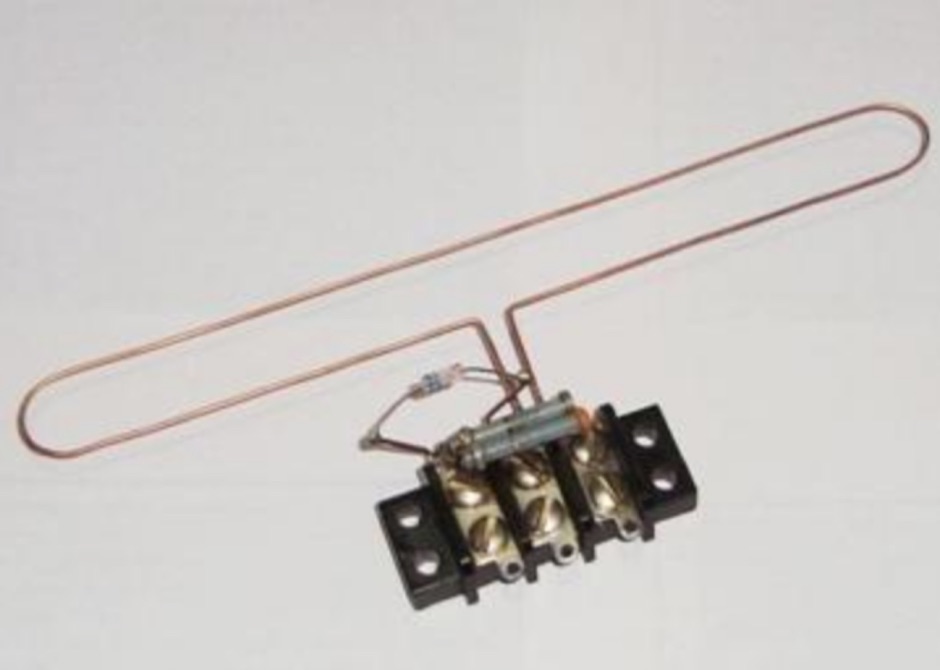 A simple UHF Crystal Radio wired up to check for reception of VHF/UHF signals in the vicinity of the shack.
 -
 A DIY Automatic Band Decoder (ABD) project, designed for dual-radio operation, addresses the common challenge of integrating band data with older transceivers lacking dedicated outputs. This particular build utilizes an AVR AT90S8515 microcontroller and a 16x2 Liquid Crystal Display (LCD) to provide band information, specifically targeting Kenwood rigs via a computer's LPT port. The design aims for cost-effectiveness while maintaining functionality, offering a solution for hams seeking to add automatic band switching capabilities to their station without significant expense. The project outlines the core components required, including the microcontroller, LCD, and an enclosure, noting that the Printed Circuit Board (PCB) fabrication and AVR programming might present challenges for some builders. It details the input requirements, such as a four-pin input and PTT for each radio, along with a 13.8V DC power supply. The decoder provides 2x6 outputs capable of sinking 500mA, suitable for controlling external devices like antenna switches or filters. Despite the original unit being damaged by a lightning strike in 2004, the author confirms its successful operation prior to the incident and mentions plans for a revised version. The resource includes a schematic in PDF format and images of the finished PCB and assembled unit, demonstrating the practical implementation of the design.
 -
 Collection of several Crystal Radio receiver circuits with schematics diagrams and pictures
 -
 Crystal receivers, construction projects and plans, old-time crystal sets, hints, crystal receiver store.
 -
 The Kenwood TS-870S HF transceiver features two state-of-the-art 24-bit 20 MIPS DSP chips, providing over 100dB out-of-passband attenuation and CW bandwidth adjustable to 50 Hz. It operates across 160-10 meters with 100 watts output, incorporating digital filtering, a beat canceller, and 100 memory channels. The radio also includes a transmit equalizer, RX antenna input, and a K1 Logic Keyer, enhancing signal processing and operational flexibility for amateur radio operators. Advanced capabilities include IF stage DSP, dual noise reduction, and an auto notch filter, all contributing to superior signal reception and clarity. The TS-870S offers a variable AGC, voice equalizer, and an RS-232C port for computer control, with Windows™ software supplied. Its built-in automatic antenna tuner functions on all bands for both transmit and receive modes, streamlining station setup and operation. Available accessories such as the DRU-3A digital recording unit, SO-2 high stability crystal oscillator, and VS-2 voice synthesizer option further extend the transceiver's utility. The unit requires 13.8 VDC at 20.5 Amps and is supplied with an MC-43S hand microphone, making it a comprehensive station component.
 -
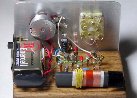
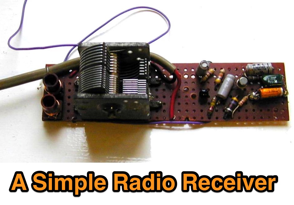 A very simple experimental short wave radio receiver. This is basically just a crystal radio with two stages of transistor amplification afterwards made with scrap components.
 -
 Crystal radio home made projects by DL2XM
 -
 VU2NAN Nandu's Crystal Radio Pages
 -
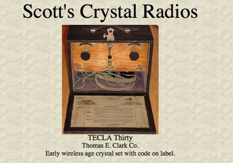 The TECLA Thirty, an early wireless age crystal set, is featured among a gallery of over 100 collectible headphones, with detailed close-up photos of vintage models. Several pages offer vintage headphones for sale, including Brandes, Baldwin, and Western Electric, suitable for crystal set use or collecting. Construction details are provided for a reproduction KILBOURNE AND CLARKE crystal set, built with vintage 1920s parts and featuring a miniature variable condenser for fine tuning. The resource also presents a project for a simple crystal radio and a 1-tube amplifier, complete with a schematic and component diagram, suitable for driving a horn speaker or amplifying weak signals for headphones. Instructions for mounting argentiferous galena detector crystals are included, along with information on MRL Handbooks covering crystal detectors and modern diodes. Additional projects include a 2A3 single-ended triode tube amplifier and two stereo tube amps using 12AX7, 6V6, 5Y3G, 6SN7, VT-25, and 5U4G tubes.
 -
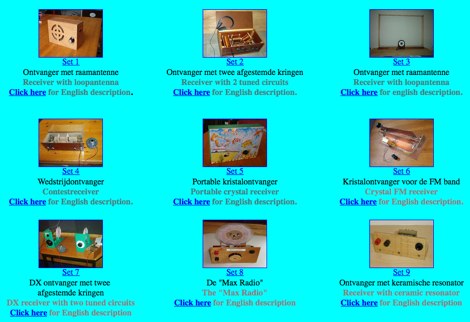 Crystal receivers are radio receivers that work without a power supply or batteries. Gallery of some crystal radio projects
 -
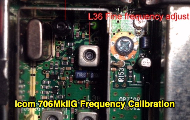 Unlike older radios, the 706 uses only one crystal oscillator (called the Master Oscillator). All other frequencies in the radio (L.O., 3-4 I.F. stages, VFO, and CW-offset) are computer-derived from the Master Oscillator. This makes it relatively simple to frequency-align the radio, so that it agrees with the Frequency Display in all modes.
 -
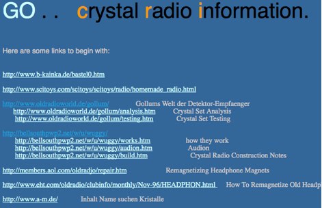 A list of links on Crystal Radio projects and related reources
 -
 Recently, at the Ballarat Hamfest, the author acquired an old Marine transceiver for just $10, charmed by its sturdy construction and waterproofing. Made by Findlay Communications in Sydney, this crystal-controlled transceiver had been dormant but was reinvigorated with minor fixes. A manual was sourced, and further repairs were made, including an ingenious crystal oscillator replacement using an Si5351a controlled by an Arduino. The refurbished radio, complete with a fresh coat of paint and added customizations, is now operational for 160m AM and 30m SSB. A successful and cost-effective restoration.
 -
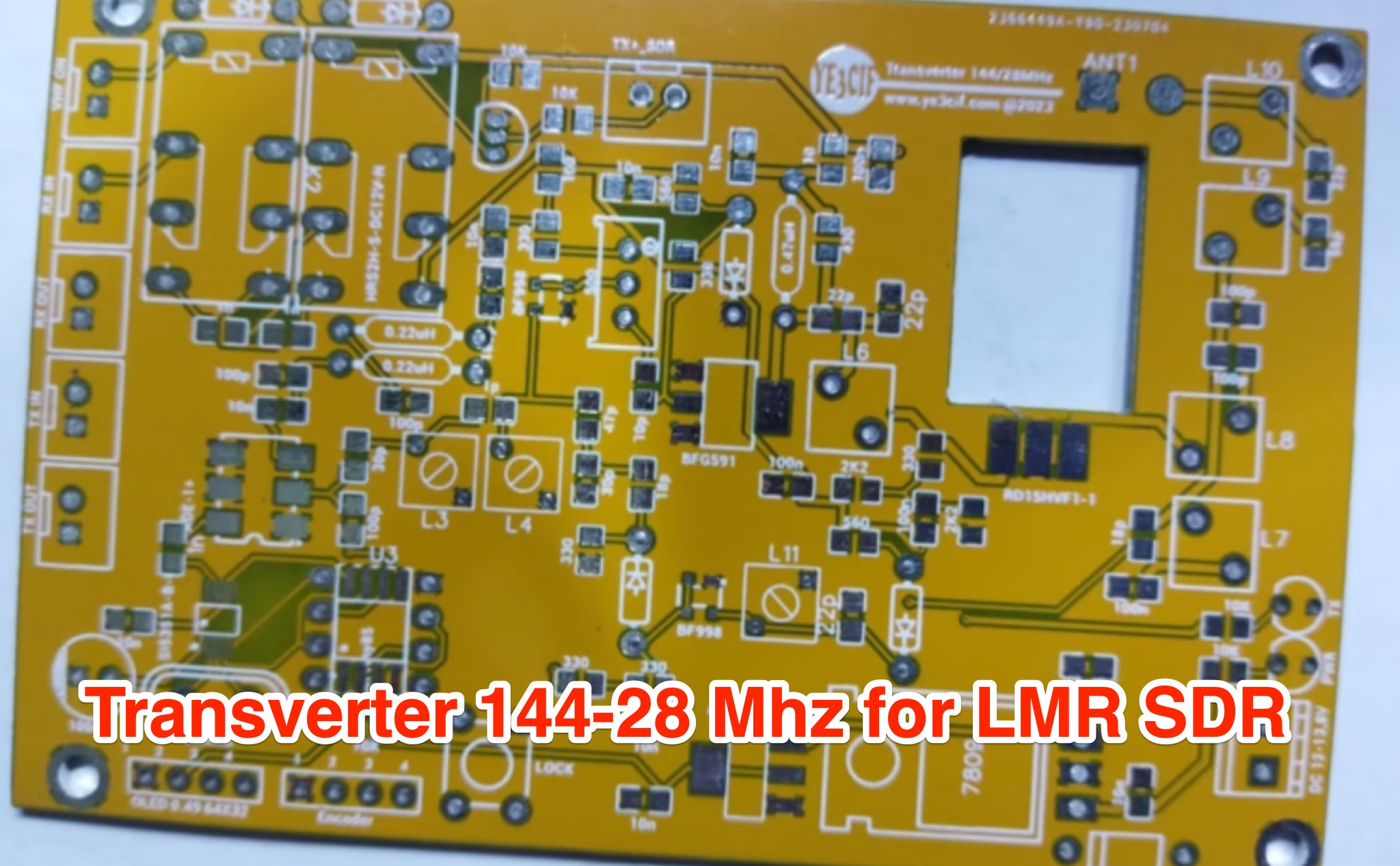 Learn how to build a VHF 144MHz transverter connected to an LMR SDR radio using easily accessible components. The transverter works by mixing the 144Mhz input frequency with a 116 MHz local oscillator frequency. Explore the challenges of finding a 116 MHz crystal and the solution of using a programmable Si5351A oscillator. Follow the provided schematic for the RX and TX sections. The transverter design is still a work in progress, with ongoing trials to achieve optimal results.
 -
 This program simplifies the complex jumper calculations for the PRF1520 radio, which can be a pain to determine manually. It supports common crystal frequencies and channel spacings, advising if a desired frequency is achievable. A recent feature allows determining unknown frequencies of a newly obtained radio by setting the jumper positions and other parameters.
 -
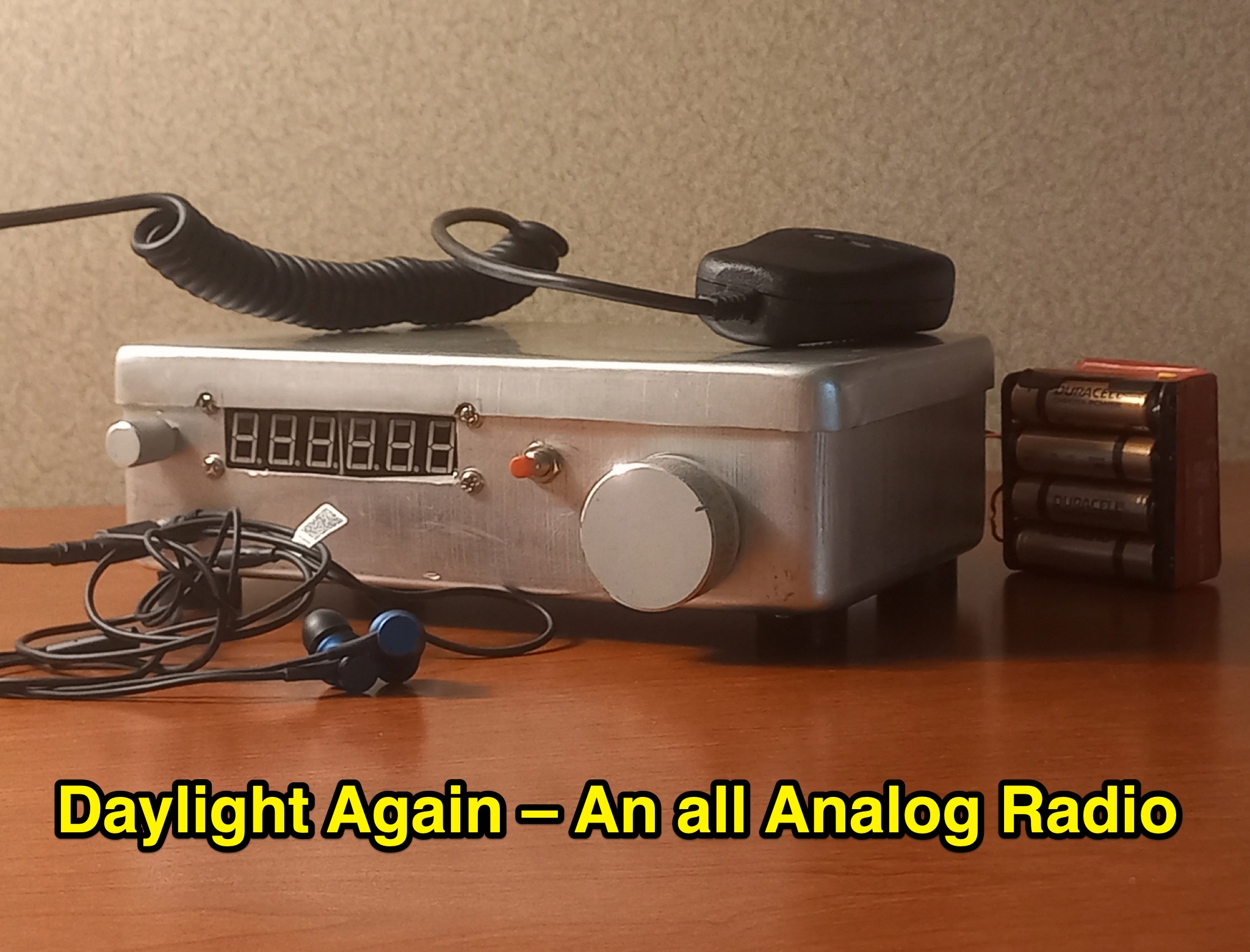 This article discusses a high performance, 7MHz, 5 watt SSB rig, the Daylight Radio, an all-analog radio design from the 1980s that includes a full circuit diagram, IMD NR60 calculations, QER crystal filter, bandpass filter, receiver portion, and more. The author explores the design, components, and functionality of this analog radio for hams interested in vintage or homebrew radio projects.
 -
 This page describes a project involving repurposing the Weathalert receiver for controlling a radio club's beacon system remotely. The author details the modifications made to the receiver, including changing the crystal frequency and adding a DTMF decode chip and PIC for remote control. The project aims to enable the turning off of beacons to prevent interference, with plans to control each beacon and the Packet Radio digi. The article provides insights into the technical aspects of modifying the receiver and showcases the author's experimentation with different crystals for optimal performance.
 -
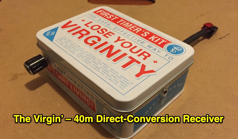 Demonstrates the construction of 'The Virgin', a **direct-conversion receiver** specifically designed for the 40m amateur radio band. This project, completed in February 2016, features a fixed operating frequency determined by a crystal oscillator, requiring a physical crystal change to alter the reception frequency. The design incorporates two integrated circuits and a power regulator, emphasizing simplicity with a single control knob. The author details the initial design, subsequent modifications to the front end, and troubleshooting steps addressing common issues like audio motorboating and power supply instability. The resource presents the final design of the receiver, reflecting the author's first experience building such a unit between December 2015 and February 2016. It offers practical insights into basic circuit construction and the iterative process of refining a homebrew radio project. The content is particularly relevant for those interested in fundamental receiver principles and hands-on **QRP** transceiver building.
 -
 The W6PQL 23cm Beacon Project describes a **1296 MHz** beacon designed for microwave propagation studies and equipment testing, capable of 30 watts output. It utilizes a PIC 16F628A microcontroller to generate CW and FSK keying for a crystal oscillator, followed by a series of frequency doublers and triplers to reach the target frequency. The final power amplification stage employs a Mitsubishi M57762 module, providing a robust 10-watt RF output. The design emphasizes stability and reliability for continuous operation, with the microcontroller code, written in assembly, provided for customization of the beacon's callsign and message. Originally located in CM97am and aimed at 140 true, the beacon used four 4-foot Yagis stacked vertically for a total ERP of 3kW. The article includes schematics, parts lists, and construction notes to guide builders, along with antenna pattern measurements. Although the beacon itself is no longer in service as of August 2010, the detailed documentation remains a valuable reference for amateur radio operators interested in building similar **microwave** projects or understanding beacon operation.