Search results
Query: dc grounding
Links: 8 | Categories: 0
-
 A 90-foot vertical antenna constructed from **aluminum irrigation tubing** is detailed, focusing on its innovative raising and lowering mechanism. The resource describes a **45-foot ginpole** system, allowing a single operator to erect or lower the antenna in minutes. It covers the mechanical design, including the pivot base, insulated joints for the tubing sections, and guy wire attachment points. The antenna consists of two 30-foot sections of 4-inch tubing and one 30-foot section of 2-inch tubing, stacked with the smaller diameter at the top. The electrical design incorporates PVC "condulet" boxes at the 30-foot and 60-foot points, housing relays to change the effective height for multi-band operation on 160, 80, 40, and 30 meters. Ferrite rod inductive chokes are used for DC control and to tune out gap capacitance. The antenna is fed with 1000 feet of open wire line, connected to a matching transformer comprising stacked toroids and a coaxial/toroidal balun. Grounding is achieved with a 3x3 foot grid of 16-gauge tinned copper wires with soldered crossovers.
 -
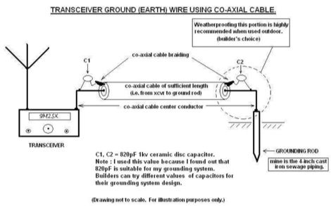 Improper grounding or earthing system can cause several unwanted RF interferences (RFI) to television sets, broadcast receivers, hi-fi sets and telephone sets. In this Article the author explain how to setup a proper radio shack grounding using coaxial cable and ceramic disc capacitor
 -
 Radio frequency systems require robust protection against transient voltage events, which can severely damage sensitive equipment. This resource details a range of **RF surge protection** devices, including models with DC Pass, DC Block, Bias T, and Ultra Low PIM characteristics, designed to safeguard critical infrastructure. It also presents various RF filtering solutions and interconnect components, emphasizing their role in maintaining signal integrity and operational continuity across diverse applications. The site provides information on products engineered for both RF and data line protection, highlighting their utility in preventing downtime and equipment loss. Specific product categories encompass coaxial protectors, grounding items, and fiber optic solutions, indicating a broad scope of application from amateur radio installations to industrial and telecommunications networks. Furthermore, the resource mentions the availability of NOM-certified products and offers same-day shipping for many items, underscoring a commitment to rapid deployment and compliance with industry standards.
 -
 The Elecraft K2 transceiver requires specific modifications for optimal soundcard digital mode operation, particularly for PSK31. The original article, circa 2001, details initial challenges with manual PTT and speech compression settings. A key modification involves adding headphone audio and a compression disable signal to the K2's microphone jack, utilizing pins 4 and 5. The **COMP0** signal, active low, is shorted to ground via a non-inverting open collector switch circuit, comprising two resistors and two transistors, mounted on the SSB board near U3. This circuit provides effective control of an analog signal line with good noise immunity. The switchbox itself repurposes a computer COM port switch, using only two of its original connectors and four of the nine poles. It integrates a microphone preamplifier, a PTT circuit built with 'flying leads' construction, and RCA jacks for soundcard connections. A trimpot adjusts the audio drive to the K2. The central DB9 connector links to the K2's mic connector via a shielded RS232 serial cable, ensuring proper grounding and signal routing. An external footswitch PTT jack is also included. Further enhancements include a **noise-canceling microphone** preamp based on a QST December 2000 article, adapted for Heil mic elements. This preamp, built with pseudo-Manhattan style construction, provides a gain of approximately 2 by changing emitter resistors (R9 and R16) from 680 ohms to 330 ohms. A 10-ohm series resistor and 47 µF capacitor on the +5V supply mitigate noise spikes.
 -
 Mitigating RF noise in a mobile operating environment, particularly within a _Jeep TJ_ vehicle, presents unique challenges due to the vehicle's electrical system and chassis characteristics. This resource details practical methods for identifying and suppressing various forms of radio frequency interference (RFI) that can degrade receiver performance for both CB and amateur radio transceivers. It covers common noise sources such as ignition systems, alternators, fuel pumps, and computer modules, explaining how these components generate broadband or specific frequency noise that impacts radio communications. The guide offers actionable solutions, including proper grounding techniques, the strategic use of ferrite beads and toroids on power and data lines, and the installation of bypass capacitors. It discusses the effectiveness of different filtering strategies for DC power lines and antenna feedlines, illustrating how a clean power supply and shielded cabling can significantly reduce conducted and radiated noise. The information presented helps operators achieve a lower noise floor, improving signal-to-noise ratio and enabling clearer reception of weak signals, which is crucial for effective mobile DXing or local ragchewing.
 -
 Operating a ham station often involves encountering radio frequency interference (RFI), RF feedback, or RF burns, which are frequently misattributed to poor equipment grounding. This resource meticulously dissects these assumptions, asserting that RF grounds on the operating desk often merely mask more significant system flaws. It identifies five primary causes for RF problems, including antenna system design flaws, proximity of the antenna to the operating position, DC power supply ground loops, equipment design defects, and poorly installed connectors or defective cables. The content emphasizes that issues like "hot cabinets" or changes in SWR when connecting a ground indicate substantial RF flowing over wiring or cabinets, a phenomenon known as common-mode current. The article provides detailed explanations of common-mode current generation, particularly from single-wire fed antennas like longwires, random wires, and OCF dipoles, which inherently present high levels of RF in the shack. It also illustrates how vertical antennas, lacking a perfect ground system, can excite feed lines with significant common-mode current. Through simulations, the author demonstrates how a dipole without a proper _balun_ can cause RF problems at the operating desk, showing current patterns and voltage distributions on feed line shields. The discussion extends to the proper application of _RF isolators_ and _ferrite beads_, clarifying their role in modifying common-mode impedance on cable shields and cautioning against their use as a band-aid for fundamental system defects. The resource advocates for correcting the actual source of RF problems, such as antenna system issues or poor connector mounting, rather than relying on internal shack grounding or isolators. It highlights that properly functioning two-conductor feed lines, like coaxial or open-wire lines, should result in minimal RF levels at the operating position, even without a desk RF ground. The author shares personal experience, noting that his stations since the late 1970s have operated without RF grounds at the desks, relying instead on proper antenna system design and feed line integrity.
 -
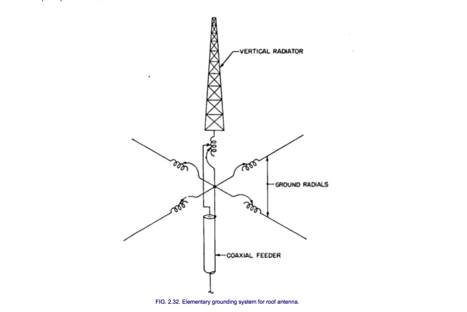 When a broadcast antenna is to be placed on top of a building, there are special problems of feeding and grounding. The radiator is usually electrically short, that is, much less than one-quarter wavelength high.
 -
 The Terminated End Fed Vee Antenna (TEFV) is a travelling wave antenna with constant current distribution. Unlike traditional resonant antennas, TEFV operates without standing waves, using a terminating resistor for broadband efficiency. With a combination of vertical and horizontal polarization, it offers wide bandwidth from 1.8 MHz to 30 MHz, eliminating the need for a tuner. Key components include a 9:1 unun transformer and a 500-ohm terminating resistor. Grounding and counterpoise enhance performance, and it can handle power losses of up to 30%. TEFV provides an effective, versatile antenna solution for amateur radio and broadcast applications.