Search results
Query: diy swr meter
Links: 12 | Categories: 0
-
 The project details a DIY SWR/Wattmeter designed around an _Arduino Uno_ shield, providing capabilities to measure RF power from 2 to **200 watts** and Standing Wave Ratio (SWR) for HF amateur radio bands. This construction features a compact design, integrating the measurement circuitry directly onto a custom PCB that interfaces with the Arduino Uno microcontroller. Key components include a directional coupler for sensing forward and reflected power, precision rectifiers, and analog-to-digital conversion for processing RF signals. The Arduino firmware handles calibration, calculations, and displays the results on an integrated LCD, offering real-time feedback on antenna system performance. The design prioritizes simplicity for homebrewers. Performance specifications indicate accurate readings within the **2-200W** power range, suitable for typical QRP to medium-power HF operations. The project provides schematics and a basic overview of the software logic.
 -
 Constructing a **2-meter** J-pole antenna from readily available copper plumbing components offers a robust and cost-effective solution for VHF operation. This design, dubbed the "Plumber's Delight," functions essentially as a half-wave dipole fed by 50-ohm coax via a **gamma match**. It incorporates a quarter-wave copper tubing support, which, when affixed to a metal mast or tower, enhances forward power in the direction of the radiating elements. The original configuration utilized a small ceramic trimmer capacitor for the gamma match, suitable for up to 10 watts. A subsequent modification replaced this with a 50 pF variable capacitor housed in a plastic enclosure, accommodating higher RF power and improving weather resistance. The antenna elements are secured using a copper "T" fitting, and an SO-239 connector mounts directly to this fitting. Performance includes gain away from the support mast, and tuning is straightforward by adjusting the gamma match capacitor for a 1:1 SWR. The total cost for materials, excluding the capacitor and coax, can be under $10.
 -
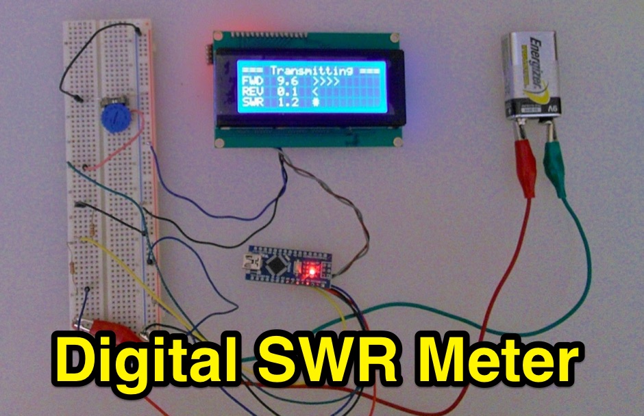 Inline RF Power & VSWR Meter. A DIY meter 0 to 30 Watt with Average and Peak. Circuit Description, Arduino Nano software code and part list to DIY your own Digital SWR Meter
 -
 An home made SWR meter for 2.4 GHz. A DIY SWR meter that allow precise measurements and calibration of any WiFi antenna. This is test equipment everyone who build wifi antennas should have in their shack. Article is in french and include some videos.
 -
 The circuit is based on two AD8307 log amplifiers, which are connected to the forward and reflected ports on a directional coupler
 -
 Demonstrates the construction and tuning of a **20-17-15 meter fan dipole** using 12-gauge PVC insulated copper wire and an Alpha-Delta C kit feedpoint. The project details the use of 14-inch pine dowels with 6-inch spaced holes to maintain wire separation for the parallel elements. Initial tuning was performed at shoulder height, with final adjustments made after elevation to 38 feet, accounting for frequency shifts observed between ground-level and elevated antenna positions. SWR analysis graphs are presented, showing performance below 1:3 across the entire 20-meter band, below 1:2 for 17 meters, and below 1:3 for 15 meters. The author notes significant RX improvements of +3 to +9 dB, occasionally exceeding +20 dB, compared to a commercial Alpha Delta DX LB Plus. The total hardware cost for this DIY antenna project was approximately $90, with the author emphasizing the utility of an **antenna analyzer** like the RigExpert AA54 for precise tuning. The fan dipole also exhibits tunable resonance on 12, 10, and 6 meters, though with reduced efficiency. Performance comparisons on 20 meters showed the fan dipole outperforming the Alpha-Delta on long-path north-south DX contacts.
 -
 A 7 dB directional gain is reported for this portable VHF Yagi antenna design, which utilizes cut metal tape measure sections for its elements. The resource details the construction process for a 2-meter band antenna, emphasizing its ease of build and portability. It specifically mentions the design's suitability for radio direction finding (RDF), fox hunting, and communication with satellites and the International Space Station (ISS), highlighting its practical applications for amateur radio operators. The construction cost is estimated at under $20, with potential for even lower expense if salvaged materials like old tape measures and PVC pipes are used. The article references _Joe Leggio's_ (WB2HOL) original design, noting specific alterations made by the author. It also compares this design to other DIY Yagi antennas, including _FN64's_ 2-meter band and _manuka's_ 70-cm band tape measure Yagis, underscoring its unique combination of simplicity, portability, and effective performance with a 1:1 SWR achievable on the 2-meter band.
 -
 1500 watts PEP SSB is the power handling capability of the MFJ-989C HF Antenna Tuner, a popular choice among amateur radio operators. Users have shared a wide range of experiences, with some praising its durability and performance over decades of use, while others criticize its build quality and accuracy. The tuner features a built-in dummy load, SWR-wattmeter, and a balun for balanced line feeders, making it versatile for various antenna setups. However, discrepancies in RF power readings and SWR measurements have been noted, with some users finding the dual scale meter to be off by about 20% compared to a Bird wattmeter. Long-term users report that the MFJ-989C performs well with proper antenna setups, but caution against tuning at high power without initial adjustments at lower power levels. Some have experienced issues such as arcing when exceeding 400 watts, while others have had no problems even at higher power levels. The roller inductor and capacitors are functional, though some users have had to perform maintenance like tightening screws or cleaning components to ensure reliable operation. Despite mixed reviews, the MFJ-989C remains in production, suggesting continued demand. It's a tuner that requires careful handling and possibly some DIY fixes to achieve optimal performance.
 -
 This article documents the author's journey in building, modifying, and testing a DIY short vertical antenna for 40, 30, and 20 meters, with potential 80m capability. Initially inspired by Parks On The Air (POTA), the author explores pedestrian mobile operation and details various experiments to enhance antenna performance. The piece highlights challenges, SWR tuning, portability, and practical results, emphasizing a balance between efficiency and size. Ultimately, it showcases the adaptability of DIY antennas for portable ham radio applications.
 -
 Presents a detailed construction guide for a 9 dB, 70cm collinear antenna, utilizing readily available _RG58/U_ coaxial cable and PVC pipe for housing. The resource outlines the critical calculations for ½ wavelength sections at 444 MHz, incorporating the coaxial cable's velocity factor of 0.66, which yields a section length of 223 millimeters. It specifies the preparation and soldering of eight such half-wavelength sections, each cut to 231mm to allow for trimming, forming the core of the array. Further instructions detail the integration of a ¼ wave element (169mm #16 solid wire) at the top and a ¼ wave aluminum tube (160mm, 5/16 inch) at the bottom, crimped to the feed point's braid. The guide also addresses RF common mode current suppression by suggesting the use of _FT50-43_ toroids on the feedline. Final assembly steps cover mounting the antenna within ¾" PVC pipe using a wooden dowel, waterproofing connections, and initial SWR checks. The article also discusses scaling the design for different element counts and other VHF/UHF bands.
 -
 The 1/4 wavelength vertical antenna project, initially designed for 20 meters, has evolved into a versatile portable solution covering 10 through 60 meters. K0BXB details its construction, emphasizing a bottom-loaded design with a tapped loading coil and four 10-foot counterpoise wires. The author shares personal experiences and field results, including **18 QSOs** during a park activation on 17m and 30m with 10 watts, and a **2,435-mile** contact with a contest station in Bonaire on 20m using 5 watts. Comparisons are drawn to commercial offerings like the _Wolf River Coils TIA_ and _QRPGuys Triband Vertical_, highlighting the DIY antenna's small footprint, light weight, and ease of tuning for POTA activations. The resource includes insights into using test equipment such as the _NanoVNA_ for SWR optimization and discusses various radiator lengths, from 17-foot wire to a 102-inch whip, demonstrating adaptability for different portable setups. Construction tips cover coil winding, tap placement, and connecting feedlines and radials using common components.
 -
 Fifty-one MHz operation, often called the "magic band," benefits significantly from a well-designed antenna, and this resource details the construction of a rigid 6-meter _Moxon antenna_ using common DIY store materials. The author, 4L/G8BAG, shares his experience with the 6m band, highlighting its potential for long-distance contacts, with single-hop sporadic E propagation enabling QSOs up to **2,500 km** and multi-hop contacts reaching **10,000 km**. The project emphasizes cost-effectiveness and durability, utilizing yellow gas pipe with an internal stainless steel lining for the antenna elements. The article provides specific dimensions for the Moxon rectangle, derived from the 12mm internal diameter of the gas pipe's steel core, rather than the outer plastic. It also details the use of white PVC water pipe for insulators and mounting, ensuring a tight fit with the yellow gas pipe. Initial testing with an MFJ antenna analyzer showed an excellent 1:1 SWR across the 50-52 MHz range, even when using 75 Ohm satellite cable as a feeder. The construction process is straightforward, involving cutting and bending the gas pipe, fitting insulators, and connecting the feedline. The author's successful on-air results, including a 1000 km contact with a temporary vertical, underscore the effectiveness of the 6m band and the Moxon design. The resource concludes with a note on exploring heavier gauge gas pipe for future 10m antenna projects.