Search results
Query: horizontal loop
Links: 38 | Categories: 0
-
 The antenna is a 10 - 160 meter horizontal loop fed with 450 ohm ladder line all the way into the ham shack to an Palstar AT1500BAL balanced line antenna tuner
 -
 Details the construction and optimization of antenna systems for amateur radio satellite operations, focusing on practical, homebrew solutions for VHF/UHF bands. It covers building _groundplane antennas_ from salvaged materials, recycling old beam antennas into new configurations like a 2-meter crossed yagi, and constructing a 10-meter horizontal delta loop. The resource also explains antenna matching techniques, including folded dipole driven elements and quarter-wave transformers, along with the importance of accurate SWR measurements and minimizing coax loss. Demonstrates how to achieve a **1:1 SWR** by carefully trimming elements and adjusting radial angles on groundplane antennas. It provides insights into selecting appropriate coax and connectors, highlighting the benefits of Belden 9913 for low loss and the proper installation of _N-connectors_. The article also addresses RFI mitigation from computer birdies and presents a design for a silent triac antenna control circuit, offering practical solutions for common satellite station challenges.
 -
 Examines the operational differences between **quad** and **Yagi** antenna designs, focusing on their respective performance characteristics for amateur radio applications. The document highlights key metrics such as forward gain, front-to-back ratio, and bandwidth, which are crucial for effective DXing and contesting. It discusses how element configuration, boom length, and material choices impact the efficiency and radiation patterns of each antenna type across various HF bands. Practical considerations for antenna builders are addressed, including structural integrity, wind loading, and overall weight, particularly when using fiberglass spreaders for quads. The resource also covers precipitation static reduction in quads due to their closed-loop design and their ability to operate efficiently at lower elevations compared to Yagis. It provides insights into dual-polarization feed systems for quads, offering independent vertical and horizontal feed points for enhanced operational flexibility.
 -
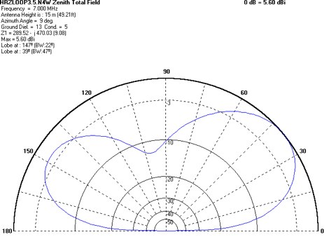
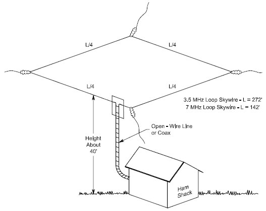 An horizontal full wave wire loop antenna for the 80 meters band by W4HM
 -
 These omnidirectional antennas offer Horizontal polarization, and about 2.1 dbd of gain. They are much quieter than a dipole or a vertical, have a broader bandwidth and will usually out perform a dipole antenna.
 -
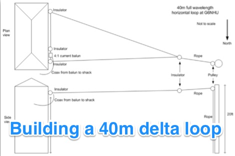 Building a 40m (7MHz) horizontal delta loop wire antenna in the backyard that is easy and quick to setup
 -
 This PDF document, authored by KT4QW in October 2004, details the construction and modeling of a dual-band, horizontally polarized hanging rectangular loop antenna for **10 and 17 meters**. The design, adapted from *The ARRL Handbook*, utilizes _NEC4WIN95_ software for scaling and optimization, targeting a 50 ohm feedpoint impedance. The resource includes a bill of materials, step-by-step construction instructions, and a discussion of the antenna's radiation characteristics. It presents NEC-generated elevation and azimuth patterns, comparing the loop's performance to a half-wave horizontal dipole at the same height and frequency. The 17-meter element is centered at 18.140 MHz for low SWR across the phone band, while the 10-meter element is centered at 28.500 MHz. Construction involves 14-gauge stranded copper wire and Schedule 40 PVC spreaders, with the total wire length calculated by the formula: Length in feet = 1005/MHz. The feedpoint impedance can be adjusted by modifying the rectangular aspect ratio. The document specifies hoisting the antenna to at least a half-wave above ground for testing. It notes that a balun was tested and found to have no measurable effect on SWR or radiation characteristics. A 2-meter scale model is presented to illustrate the physical design, and a "rotator" string is incorporated for directional adjustment up to 90 degrees.
 -
 Antenna data, and design note for this horizontal loop antenna resonating on 80 Meters by K0ZE
 -
-
 A copper pipe Hentenna for 144 MHz. The Hentenna, a compact, high-gain loop antenna developed in Japan in the 1970s, offers approximately 5.1 dBd gain, comparable to a three-element Yagi. Adapted for 2 meters, it is crafted from copper pipe for simplicity, affordability, and broadband performance. Requiring no feed-point tuning, its construction involves soldering standard copper fittings. Installation demands non-conductive materials to minimize signal disruption. Versatile for vertical or horizontal polarization, it is ideal for FM, repeater, SSB, or CW applications. This design emphasizes practicality and performance for amateur radio enthusiasts
 -
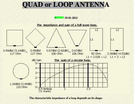 Quad and loop antennas comparisons, evaluating the impedance and gain of both antennas and considerationso n horizontal loop antennas for low bands by PA0FRI
 -
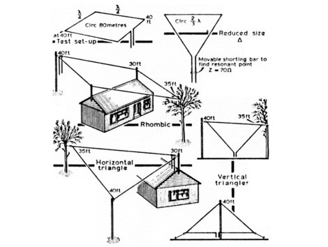 Theory of horizontal loop antennas, as discovered by G2PL using a lowered quad antenna and theorized by ZS6AKA
 -
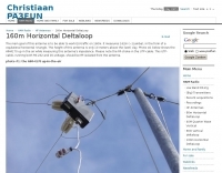
 A Wire resonant loop antenna for 160 meters band article by N4KC
 -
 This PDF document details the construction of a **70 MHz** Big Wheel antenna, a horizontally polarized omnidirectional array. The design utilizes three full-wave loops, each approximately **2160 mm** in diameter, arranged in a triangular configuration. The resource provides mechanical dimensions for the antenna elements and a comprehensive bill of materials, specifying component quantities and types, such as M8 stainless steel bolts, 15x15x1.5 mm square aluminum tubing for spacers, and 8 mm aluminum rod for the arcs. The central hub is constructed from two 160x160x8 mm aluminum plates, with four 40 mm long polyamide insulators supporting the radiating elements. The feed system incorporates a 50 mm diameter aluminum pipe for mounting and a matching stub constructed from a 120x20x2 mm aluminum sheet, connected via M8x10 mm bolts. The resource includes a diagram illustrating the mechanical dimensions and assembly points, including the N-connector fixing point and the center conductor attachment. The project was published on May 25, 2011, by Peter OE5MPL and Rudi OE5VRL. DXZone Focus: PDF | 70 MHz Big Wheel | Mechanical Dimensions | **2160 mm** loop diameter
 -
-
 The HF horizontal loop has been around for many years now. This article includes a YouTube video and discusses the reasons for looking at this antenna, its design, and its installation. There are some on-air comparisons against three regular double bazooka (coax) dipoles and the Par SWL End-Fed antenna.
 -
 The **136kHz Vertical Antenna** at G3YMC employs a Butternut HF2V structure, standing 10m tall. It integrates a 6.5mH loading coil to achieve resonance, with a matching transformer for impedance adjustment. The antenna's configuration includes top loading via a 12m horizontal wire, enhancing capacitive impedance. Initial measurements indicated a high impedance of around 300 ohms, necessitating a transformer for a 50-ohm match. Despite challenges with ground losses, the vertical antenna has shown improved performance in specific directions, filling nulls present in the previous loop antenna setup. The tuning remains broad, with variations due to environmental factors affecting the matching. Ongoing adjustments and comparisons with the loop antenna will continue to refine its effectiveness.
 -
 Simple 6 Metre DX Antenna based on an article by LB Cebick in QST May 2002 on a Quad Turnstile antenna. This antenna is basically two full wave loops mounted at right angles fed 90 degrees out of phase to produce an omni-directional horizontally polarized pattern
 -
 Such kind of omnidirectional antenna gives the possibility to be QRV with horizontal polarisation, as commonly used for the CW and SSB section of the 2m band. This actual design shows a 1.3:1 bandwidth of about 150kHz, centered to 144.200MHz.
 -
 This wire antenna for 40 and 20 meter band feature a good SWR. Horizontal side of the antenna is placed at two meters above the ground. Impedance of the antenna are depending by the height of the base from the ground and conditions of the ground
 -
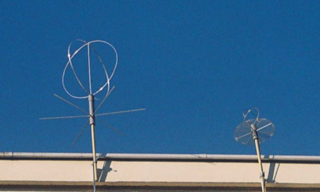 This antenna was conceived mainly for high-speed digital transmission via satellite. The antenna is made of two full waves loops , mounted at right angles to each other. Then coupled together, 90 degrees out of phase over a horizontal circular reflector. With this configuration the antenna is omni directional and circularly polarized.
 -
 An experimento of a 40 meter delta loop antenna both in horizontal and vertical polarization and several elevation angles with interesting notes about the effect of the radial field under the antenna.
 -
 This project is a full wavelength, horizontal, loop antenna for the 40 metre Amateur Radio band, built using insulated copper wire in a diamond shape, supported by egg insulators, tethered to 4 masts, each 6.5m high
 -
 This page presents an online calculator tool for determining the dimensions of various HF wire antennas operating between 1.8-30 MHz. Users input their desired resonant frequency to obtain precise measurements for four popular antenna types: standard flat-top dipole, inverted Vee, quad loop, and equilateral delta loop. The calculator provides comprehensive measurements including leg lengths, minimum heights, horizontal spreads, and feedpoint distances. Accompanying the calculator are detailed technical explanations, construction notes, and installation guidelines for each antenna type, making it a practical resource for amateur radio operators building their own antennas.
 -
 This is very common W7IUV Flag Antenna design is based on the PY3AGD antenna because it uses the antenna mounted horizontally and nd it is perfect for my small city lot installation.
 -
 WB8LZR details the construction and initial field results of a multi-band vertical wire antenna, designed to complement his existing horizontal loop for improved DX on 80 meters. The antenna utilizes a 67-foot vertical wire, configured as a quarter-wave radiator on 80m, and employs a 1:1 current balun for RF isolation on 80m, 30m, and 17m. For bands like 40m, 20m, and 10m, where the wire acts as a half-wave or full-wave radiator, an additional impedance transforming _unun_ is integrated to manage the significantly higher feedpoint impedance and voltage. The author notes the vertical's performance as a receiving antenna, observing reduced noise compared to his main horizontal loop, particularly on 80m, and even hearing some long-path signals the loop missed. Initial QRP contacts, including a **1-watt** QSO with a _VP2 station_ on 30m, demonstrate its transmit capability. While the radial system is currently rudimentary, the project outlines practical considerations for multi-band vertical deployment and impedance matching.
 -
 This project explores the construction and performance of an Alford Loop antenna as an alternative to a round loop. The Alford Loop, symmetrically fed at opposite corners, behaves like a small loop despite its larger size. Built using PVC pipes and secured with tire wraps, the antenna integrates an LZ1AQ active amplifier for optimal performance. With deep nulls in its horizontal radiation pattern and improved resonance characteristics, this design has significantly outperformed previous active antennas in reception quality.
 -
 This study details a reception comparison between vertical and horizontal active loop antennas, specifically two identical _Wellgood active loop antennas_, on various HF bands. The experiment, conducted in a densely populated QRM-prone area, monitored FT8 signals over a 24-hour period using two identical receivers. The methodology involved direct comparison of signal reception across the HF spectrum, aiming to identify performance differences based on antenna orientation. The results indicate that vertical loops demonstrated superior performance on higher bands (10m, 15m, 20m), while horizontal loops excelled on lower bands (30m, 40m, 160m), particularly for receiving long-distance (DX) signals. The horizontal loop's advantage on lower bands is attributed to potentially better low-angle performance and reduced sensitivity to man-made noise, yielding a **2-3 S-unit** improvement on 160m. The study provides practical insights for optimizing antenna placement in challenging urban environments, noting that the horizontal loop consistently showed a **10-15 dB** signal-to-noise ratio improvement on lower bands.
 -
 An cheap and efficient wire antenna for lower HF bands. This closed loop antenna, radiates perpendicular to its plane with a bi-directional radiation pattern. With a gain of 2 dB over a diplole it is a low noise sensible antenna. Requires a tuner if you want to use as a multiband antenna.
 -
 Discover the success story of creating a 4-meter Delta Loop antenna, ideal for improving radio communication. This horizontally polarized antenna offers efficient performance when mounted at VHF heights, catering to both HF and VHF characteristics. A simple, DIY project suitable for portable setups, providing versatile options for radio enthusiasts.
 -
 This is a 50 MHz WebSDR receiver, located in Ashford, CT, USA FN31VU using a deltaloop turnstile horizontally polarized omnidirectional antenna.
 -
 A vertical delta loop is a practical antenna for low bands, popular for its simple design requiring just one support. Its shape, an equilateral triangle in free space, yields optimal gain and radiation resistance. Deviating from this shape lowers performance. The delta loop can be polarized either horizontally or vertically based on the feed point location. In vertical polarization, it acts as two quarter-wave verticals with the baseline feeding one side. This design minimizes radiation from the baseline while maintaining effective operation.
 -
 Learn how to design a Hentenna antenna, a portable asymmetrical double-loop antenna ideal for amateur HF or VHF bands. This page provides details on constructing and optimizing the antenna for maximum performance in DX communications. Discover how altering the antenna's vertical feed section can adjust the VSWR resonant frequency and how changing the support pole's position can alter the beam direction. Originally developed by Japanese 6-meter operators, the 'Hentenna' offers a unique design that allows for horizontal polarization when vertically oriented. Explore radiation patterns, VSWR charts, and antenna currents diagrams to optimize your antenna's performance for long-distance contacts.
 -
 Demonstrates the construction and portable deployment of a 40-meter horizontal loop antenna, often referred to as a "Sky Loop" or "DX-Buster." The design adapts a full-wavelength horizontal loop for field use, eliminating the need for traditional insulators by employing four 5-meter heavy-duty _squid poles_ and metal post bases for support. This setup facilitates rapid assembly, crucial for portable operations, with the antenna wire length specified at approximately 43-45 meters for optimal 40-meter band performance. The resource details the specific construction methodology, including winding the antenna wire around rubber caps on the squid poles and securing it with electrical tape. It provides a parts list and assembly techniques, focusing on minimizing components for ease of transport and quick setup. The article, originally published in the February 2013 edition of the Central Coast ARC "Smoke Signals" magazine, reflects practical experience. This documentation offers a field-deployable 40-meter loop antenna solution, utilizing readily available components like fiberglass squid poles. It presents a practical approach for operators seeking a robust, portable antenna for the 40-meter band, emphasizing simplicity and efficiency in its design and deployment.
 -
 Cloverleaf antenna is a circular polarized antenna which is way better than the cheap dipole antenna that comes with video transmitters and receivers. The Cloverleaf is a closed loop antenna which the signal and ground wires are connected. The cloverleaf antenna has 3 loops at 120 degree apart, and they are titled at 45 degree to horizontal plane.
 -
 The tri-band trapped delta loop antenna design operates on 80 meters (3.5–4 MHz), 40 meters (7–7.3 MHz), and 30 meters (10.1–10.15 MHz) using a single triangular wire loop. This configuration eliminates the need for an external antenna tuner or band-switching relays. The antenna's physical perimeter, approximately 270 feet, establishes 80M as the fundamental band, with specific trap placements enabling resonance on 40M and 30M. Trap design and placement are critical, with 30M traps positioned inboard of 40M traps within the horizontal element. Each slant leg measures approximately 80 feet. The resource references foundational information from the _ARRL Antenna Handbook_ and _ON4UN’s Low Band DXing_ regarding full-wave loop behavior and feedpoint impedances. The project aims to provide multi-band HF operation from a single, fixed antenna structure.
 -
 The K5USS 6 Meter Hentenna Project page on Hamuniverse provides detailed instructions on how to build a 6 meter directional antenna with 3.5 dBd gain. The project is presented with permission from K5USS, Charlie of Richardson, Texas. This directional antenna is a full wave loop on 6 meters, horizontally polarized but mounted vertically, with a 50 ohm impedance, ideal for 6 meter SSB operations. The page is useful for hams looking to construct their own directional antenna for improved performance on the 6 meter band.
 -
 This project involved designing a 7-pole Chebychev broadcast band filter to address severe interference issues caused by a new horizontal loop antenna on the KN-Q7A transceiver. The interference overwhelmed the transceiver’s front end, so a custom filter with a 3.5 MHz cutoff was built using silver mica capacitors and type 6 T130 toroidal cores. Encased in a diecast box with SO239 sockets, the filter blocks strong signals from the broadcast band, achieving over 100 dB attenuation. Tested up to 100W, it reduces interference effectively while maintaining low insertion loss across HF bands.