Search results
Query: lower side band
Links: 16 | Categories: 0
-
 Demonstrates the construction of **magnetic loop antennas**, detailing both multi-turn and single-turn designs. It covers a 30-inch diameter multi-turn loop for 80 meters, based on a February 1996 QST article, and an octagon single-turn loop made from 15mm copper tube with a 4.8-meter circumference, operating from 7 MHz to 14 MHz. The document also presents a smaller 800mm diameter loop for 14 MHz to 28 MHz, emphasizing the importance of high-voltage tuning capacitors. Covers the design and construction of custom **butterfly capacitors** and piston capacitors, including a split stator capacitor with 140 pF capacitance and a 6000 Volt rating, and a butterfly capacitor with 5-65 pF and 7200 Volt rating. It explains why butterfly capacitors are preferred over split stator types for high power applications due to lower losses and direct series connection of rotors, reducing resistive losses from wiper contacts. Material recommendations include clear PVC for plates and brass or stainless steel for non-magnetic hardware. Addresses practical considerations such as feeding the loop with a shielded 1/5 Faraday loop made from RG213 or RG8 coax, achieving VSWR 1.1 across bands, and optimizing its placement 180° from the capacitor. It also discusses mechanical joint resistance, dissimilar metal oxidation prevention using Vaseline, and a simple method for determining radiation angle with a TL-light tube. The guide includes diagrams for rotor, stator, and end plate construction.
 -
 Examines the operational differences between **quad** and **Yagi** antenna designs, focusing on their respective performance characteristics for amateur radio applications. The document highlights key metrics such as forward gain, front-to-back ratio, and bandwidth, which are crucial for effective DXing and contesting. It discusses how element configuration, boom length, and material choices impact the efficiency and radiation patterns of each antenna type across various HF bands. Practical considerations for antenna builders are addressed, including structural integrity, wind loading, and overall weight, particularly when using fiberglass spreaders for quads. The resource also covers precipitation static reduction in quads due to their closed-loop design and their ability to operate efficiently at lower elevations compared to Yagis. It provides insights into dual-polarization feed systems for quads, offering independent vertical and horizontal feed points for enhanced operational flexibility.
 -
 5 Band 1/4 wave Telescopic Antenna. The 20m to 10m, antenna is simple and cheap to make, and has a performance that matches commercial antennas but at cost considerably lower. The design was purposely based on a telescoping fibre glass fishing rod as this allows it to be easily stowed away in the car.
 -
 JJ0DRC's HF multi-band delta loop antenna project, initially conceived during the waning peak of Cycle 23, addresses the common challenge of achieving effective DX operation from a small residential lot in Japan. Dissatisfied with a ground plane antenna's performance in SSB pile-ups, the author sought a beam-like solution without a tower, drawing inspiration from a JJ1VKL article in CQ Ham Radio Sep. 2000. The antenna, constructed in October 2000, employs two 7.2-meter fishing rods (37% carbon fiber, reinforced with cyano-acrylate glue and aluminum tape) and 1mm enameled wire, fed by an Icom AH-4 external antenna tuner. While the exact beam pattern remains unmeasured, JJ0DRC observed a significantly higher callback rate compared to dipole antennas, particularly on higher bands. The system's circumference length of 15-20m is crucial for maintaining a good beam pattern across HF bands, though performance on lower bands like 80m, 40m, and 30m becomes less directional as the length deviates from a full wavelength. Ongoing maintenance addressed degradation issues, including aluminum tape cracking and wire breakage at connection points due to strong winds (often exceeding 10-15m/s in winter). The author reinforced rod connections with IRECTOR PIPE SYSTEM components and INSU-ROCK ties, and improved wire attachment methods using Cremona rope and epoxy bond to enhance durability.
 -
 The document provides a detailed guide on modifying an inverted-L antenna to include the 160 meters band. This enhancement allows amateur radio operators to utilize the lower frequency effectively, which is crucial for long-distance communication, especially during the night. The inverted-L design is popular due to its compact size and ease of installation, making it suitable for various environments. By adding top band capabilities, operators can engage in DXing and contesting on 160m, expanding their operational range and opportunities. The guide includes practical tips and considerations for construction, ensuring that the antenna maintains its performance across the extended frequency range. It discusses the necessary adjustments and materials required for the modification, along with potential challenges and solutions. Whether you are a seasoned operator or a beginner, this project can enhance your station's capabilities, allowing for more versatile operations and improved signal quality on the 160m band.
 -
 Demonstrates the design principles and performance characteristics of **corner reflector antennas**, emphasizing their high gain and directional properties. It covers critical design factors such as the corner angle and the spacing between the radiating dipole and the reflector vertex. The resource explains how reducing the corner angle increases gain but lowers feed impedance, making matching more challenging. Practical angles of 90 degrees or 60 degrees are discussed, with 90 degrees offering easier impedance matching despite slightly lower gain. Details key design considerations, including reflector side length exceeding two wavelengths and reflector width greater than one wavelength for a half-wave radiator. It specifies reflector construction using wire netting, sheet metal, or parallel metal spines spaced less than 0.1 wavelength. The article provides a table with general dimensions for UHF and VHF bands, noting typical impedance values of 50 to 75 ohms and expected SWR of 1.7:1 on the lower band edge. Adjustable radiator-to-vertex spacing is highlighted as crucial for final tuning.
 -
 The resource details the construction of a homebrew 50-watt FET amplifier, based on Don W6JL's _QST Homebrew contest_-winning design from 2009. It functions as an afterburner for QRP transceivers, providing a **12dB** power lift. The amplifier utilizes IRFZ24N FETs and covers the 80, 40, 30, and 20-meter bands, with the 20m LPF extending to 17m. Key technical aspects include an FT37-43 transformer for the input network, a relay-switched 3dB pad for lower bands controlled by an _Arduino Nano_, and an RF-actuated T/R switch. The LPF board integrates four relay-switched filters rated for 50 watts, using capacitors with a minimum 250VDC rating. Performance measurements indicate a power gain ranging from **4.4dB** on 20m to 8.1dB on 80m, with a required drive power of approximately 5 watts. The article also discusses thermal management, current limiting considerations, and component sourcing.
 -
 Constructing a compact directional antenna for the 17-meter band, this resource details the build process for a Moxon rectangle, a two-element Yagi variant with folded-back elements. It covers the antenna's evolution from the _VK2ABQ beam_ and provides specific dimensions for a version built using fishing pole whips. The content includes a discussion of the antenna's radiation pattern, feedpoint impedance, and its inherent front-to-back ratio, which is often superior to a standard two-element Yagi. Practical considerations for element spacing and material choices are also addressed, alongside a visual representation of the antenna's physical layout. Performance data presented includes a comparison showing the Moxon rectangle's **2.5 dB gain** over a half-wave dipole and a front-to-back ratio of **20 dB**. The resource also touches upon the antenna's relatively wide bandwidth for a two-element beam and its suitability for portable operations due to its compact footprint. It offers insights into optimizing the design for specific operating conditions and discusses the advantages of its lower take-off angle compared to omnidirectional wire antennas, making it effective for DX contacts on the 17-meter band.
 -
 The dipole shown in this document is installed in an inverted Vee configuration, with two leg elements on each side held parallel to each other by 21cm spacers. The upper leg is for 40m and the lower leg for 20m. The spacers are made of 7mm plastic garden hose support for garden sprayers cut to 21cm.
 -
 The article, "Using 75 Ohm CATV Coaxial Cable," details methods for employing readily available 75-ohm CATV hardline in standard 50-ohm amateur radio setups. It addresses the inherent impedance mismatch and practical considerations, such as connector compatibility, for hams seeking cost-effective, low-loss feedline solutions. The resource specifically contrasts common 50-ohm cables like RG-8, RG213, and _LMR-400_ with 75-ohm hardline, highlighting the latter's lower loss characteristics, particularly at VHF and UHF frequencies. It explores two primary approaches to manage the impedance difference: direct connection with an acceptable SWR compromise and precise impedance transformation. The direct connection method acknowledges that a perfect 1:1 SWR is not always critical, especially when using low-loss coax. For impedance transformation, the article explains the use of half-wavelength sections of coax to reflect the antenna's 50-ohm impedance back to the transmitter, noting its single-frequency effectiveness. It also briefly mentions transformer designs using toroid cores and a technique involving two 1/12 wavelength sections of feedline for broader bandwidth. The content further clarifies the concept of _velocity factor_ for calculating electrical versus physical cable lengths, providing a generic formula for precise length determination. It notes that while half-wave matching is practical for 10 meters and above, it can result in excessively long runs for lower bands like 160 meters, potentially adding **250 feet** of cable. The article also mentions achieving a usable bandwidth of 28.000 MHz up to at least **28.8 MHz** on 10 meters with specific transformation techniques.
 -
 A monoband delta loop antenna for the 7 MHz. This vertically polarized DX Antenna is a full wavelength sngle side antenna and has a total length of 42.3 meters (137,1 inch) Can be easily setup with a flag pole or fishing pole as center top mast. For optimal performance lower side should be at 2 meter above the ground. This antenna offers a low radiation angle and 1 DB Gain.
 -
 F5NPV introduces a variant of the W8JK antenna design, employing the MOXON principle. With extended monopoles, it outperforms the Open-Folded W8JK, yielding a 1dbd gain improvement, enhanced performance on 30m and 10m bands, bi-directionality, and lower side attenuation. The design's focus on higher radiation impedance results in increased antenna efficiency and reduced losses. Despite these improvements, the bill of materials remains unchanged.
 -
 A vertical delta loop is a practical antenna for low bands, popular for its simple design requiring just one support. Its shape, an equilateral triangle in free space, yields optimal gain and radiation resistance. Deviating from this shape lowers performance. The delta loop can be polarized either horizontally or vertically based on the feed point location. In vertical polarization, it acts as two quarter-wave verticals with the baseline feeding one side. This design minimizes radiation from the baseline while maintaining effective operation.
 -
 Effective suppression of harmonics and parasitic radiation from HF transmitters is crucial, especially with the increasing sensitivity of VHF/UHF radio channels to interference. This project details a hybrid low-pass filter (LPF) designed to operate across the HF bands up to 51 MHz, making it suitable for 6-meter band operations while providing deep VHF/UHF suppression. The design addresses the challenge of modern interference landscapes, where even microvolt-level signals can disrupt wireless sensors and other simple VHF/UHF receivers. The filter utilizes a single elliptic link, combining high cutoff steepness with robust suppression in the hundreds of megahertz range. A key feature is the use of only two standard capacitor values, simplifying construction and component sourcing. The article provides a detailed schematic, performance characteristics, and _RFSim99_ model file, demonstrating a reflection coefficient S11 below 0.017 (VSWR < 1.03) across 1-51 MHz, ensuring minimal degradation to the antenna system. Construction notes include coil winding specifications and capacitor selection guidance, with recommendations for _FR-4_ assembly. Two capacitor sets are presented, with the first variant recommended for its lower RF current demands, keeping currents below 3 A at 1 kW passing power at 51 MHz. Fine-tuning involves adjusting frameless coils, with considerations for capacitor tolerance and high-frequency capacitance measurement accuracy.
 -
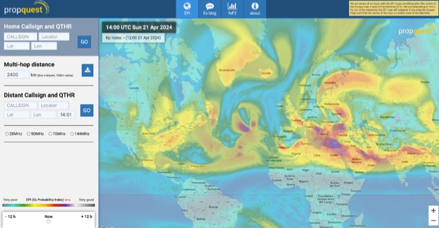 This website explains signal variations on a local radio net by tracking the foF2, a measure of ionosphere's ability to reflect radio waves. The website shows daily foF2 variations and how it affects Near Vertical Incidence Skywave (NVIS) propagation for local nets. It also considers D-layer absorption affecting lower bands and F2 MUF distance for long-distance communication. Additionally, the website tracks foEs for E-layer propagation and an EPI index for predicting Es chances.
 -
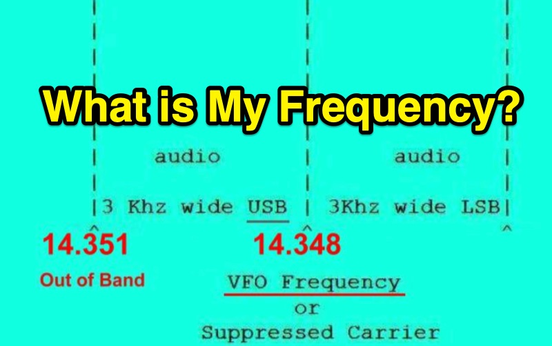 Single Sideband (SSB) operation requires careful attention to the relationship between a radio's displayed frequency (suppressed carrier) and the actual 3 kHz wide audio signal. This resource clarifies how Upper Sideband (USB) and Lower Sideband (LSB) signals occupy spectrum above or below the indicated frequency, respectively. It provides practical examples for General Class operators on the **20m** and **40m** bands, such as setting a VFO to 14.226 MHz for USB on 20m or 7.178 MHz for LSB on 40m, to maintain a safe margin from band edges. The resource emphasizes the critical importance of staying within allocated band limits to prevent out-of-band emissions, particularly when operating close to band edges. It includes relevant excerpts from **FCC Regulation Part 97**, specifically section 97.307, which details emission standards, necessary bandwidth, and spurious emission attenuation requirements. The text explains that unused sidebands are considered spurious emissions and notes that modern HF equipment typically exceeds the 43 dB spurious emission reduction standard, often achieving 60 dB or more.