Search results
Query: mast designs
Links: 10 | Categories: 1
Categories
-
 Demonstrates the iterative design and construction of a **tapped HF/VHF mobile vertical antenna** by K0EMT, detailing four generations of development. The antenna supports operation on 80m, 40m, 30m, 20m, 17m, 15m, 12m, 10m, 6m, and 2m bands. Initial designs, like Generation 1, featured a 3/8" x 24TPI bolt in a PVC end cap with a 1" aluminum tubing mast, resulting in a 9'9" overall length and resonance around 6.9 MHz with the full coil. Subsequent generations refined the mast and coil forms, transitioning from aluminum to copper tubing (Generation 3, found too weak) and eventually fiberglass for the coil form (Generation 4, in progress). Coil tapping points were adjusted to achieve resonance without an external tuner in Generation 2. The project outlines material costs, totaling approximately $25, and mentions a successful 28 MHz QSO with EA3XA using an ICOM IC-706 mk II at 100 Watts. For 80m operation, an external wire with the maximum coil setting is used, or a 56" extender below the coil for stationary use.
 -
 Presents a detailed construction guide for a **Quadrifilar Helix Antenna** (QHA) optimized for 137 MHz, specifically for receiving weather satellite transmissions. The resource outlines the author's experience building previous QHA designs, highlighting challenges with tuning and nulls, and then focuses on a refined design by John Boyer, documented by Steve Blackmore, which proved easier to build and yielded superior reception. The guide provides precise element dimensions, including 1.5m of 32mm PVC pipe for the mast and 8mm soft copper tubing for the helix elements. It specifies lengths for horizontal tubes (190mm, 90mm) and helix elements (903mm, 1002mm), along with instructions for drilling, assembly, and forming a **balun** by wrapping RG58 coax around the mast. The text emphasizes critical steps like ensuring elements are square and twisting in the correct direction to avoid phase issues. It includes references to original QST articles by Buck Ruperto (W3KH) and the WxSat program for decoding satellite transmissions, contextualizing the antenna's purpose. The article concludes with a sample NOAA 12 image from September 1998, demonstrating the antenna's reception capabilities.
 -
 Constructing a compact, single-feed triband Moxon antenna for 20, 15, and 10 meters is detailed by DU1RZ, drawing from his personal experience with space-constrained antenna projects. Initially fascinated by cubical quads, the author transitioned to Moxon designs in 2005 after realizing his roof space was insufficient for a bulky quad. His first experimental monoband Moxon for 15 meters, built from repurposed materials, provided solid DX QSOs for seven years, despite being slightly below the 21 MHz band center. The project outlines the design process, including using the _MOXGEN Calculator_ for element dimensions and material selection, such as #14 AWG enamel copper wire and fishing poles for spreaders. DU1RZ shares insights from simulations with DL2GMS regarding insulated versus non-insulated wire performance, noting that insulated wire can shift resonant frequencies lower. The assembly instructions cover preparing wire elements, connecting feed points, and tuning the antenna, with initial SWR measurements taken at 10 feet and final readings on a mast showing excellent results: 1.0:1 on 14.225 MHz, 1.1:1 on 21.250 MHz, and 1.3:1 on 28.50 MHz. Transmission tests with 4F1BYN indicated a front-to-back ratio of approximately 2 S units with 10 watts output. The author emphasizes adaptability, encouraging builders to use readily available materials rather than strictly replicating his setup. Key observations from DU1RZ and DL2GMS highlight the antenna's strong performance across 20, 15, and 10 meters, good front-to-back ratio, full bandwidth on 20 and 15 meters, and its small turning radius of about 4.18 meters (13.54 feet), making it suitable for limited antenna space. Its lightweight construction and low wind load are also noted as significant advantages.
 -
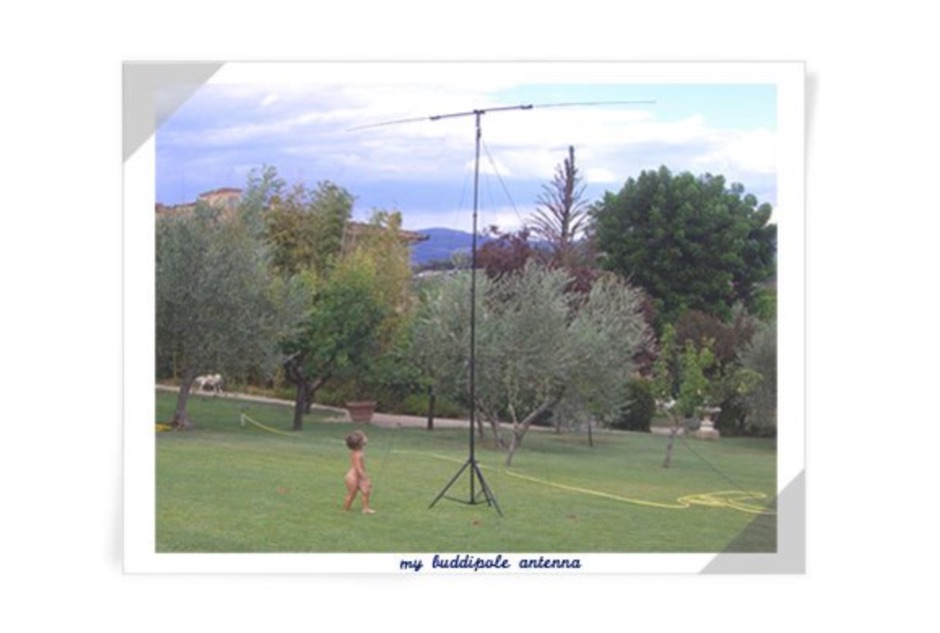 The Buddipole Deluxe, a portable HF/VHF antenna system, receives a practical assessment from IW5EDI after a month of field use. The author, constrained by antenna restrictions, highlights the system's crucial role in enabling portable operations, even managing sporadic digital activity from a balcony. Direct comparisons to a fixed 3-band dipole reveal surprisingly comparable signal reports on 15, 17, and 20 meters, underscoring the Buddipole's effectiveness in real-world scenarios. Tuning the Buddipole proves straightforward on bands down to 20 meters, though the review notes significant challenges with SWR on lower bands like 40 meters, where achieving better than 3:1 SWR was problematic. Observations also include SWR variations with dipole rotation and mast height, suggesting environmental factors play a role. The overall manufacturing quality of the antenna and its accessories, including the tripod and carry bag, is deemed good, despite a minor issue with a pole connector. Looking ahead, the author plans to construct a homemade Buddipole version, possibly optimized for the 30-meter band, specifically for PSK31 operations from an apartment. This personal project reflects a common amateur radio practice of adapting commercial designs for specific needs, further extending the utility of portable antenna concepts.
 -
 A 102-inch vertical whip, commonly a CB antenna, forms the core of this low-profile 10-meter antenna design, optimized for the 28 MHz band. The construction details specify three 8-foot radials made from scrap wire, connected to a common point. This simple yet effective setup is designed for ease of construction and deployment, making it accessible for operators with limited space or materials. The design emphasizes using readily available components, including PVC pipe for the mast and a SO-239 connector for the feedline, ensuring a straightforward build process for a resonant quarter-wave vertical. Field results indicate that this antenna provides good performance for local and DX contacts on 10 meters, despite its compact footprint. The author, N8WRL, shares practical insights into its construction and tuning, highlighting its suitability for temporary or permanent installations where a full-sized antenna might be impractical. Comparisons to more complex designs suggest that this low-profile vertical offers a respectable signal-to-noise ratio and effective radiated power for its size, proving that simple designs can yield satisfying on-air results.
 -
 Presents an alternative construction method for isolated element Yagi antennas, specifically for VHF/UHF operation. The technique utilizes commercially available vibration damping clamps (resin support blocks) to isolate 1/4-inch aluminum rod elements from a 1-inch square aluminum boom, simplifying the build process by eliminating the need for custom-machined insulators. This approach is demonstrated through the construction of 6-element Optimized Wide-Band (OWA) Yagis for the 2-meter, 1.25-meter, and 70-centimeter bands, which are well-suited for portable contesting arrays due to their light weight and decent gain. The document provides detailed specifications for element and boom materials, along with step-by-step procedures for cutting, drilling, and tapping. It also covers the fabrication of a feedpoint bracket for a direct 50-ohm SO-239 coax connection and discusses considerations for horizontal versus vertical polarization, including mast placement. The resulting 6-element models achieve an average free-space gain of 10.2 dBi and a 25 dB front-to-back ratio, with the construction technique being scalable for higher gain designs. Included are parts lists with sources, detailed mechanical drawings for each band, and EZNEC data for the 2-meter and 70-centimeter designs, showing both free-space and 30-foot elevation performance. The designs are optimized from W4RNL's original concepts using HAMCALC, ensuring good gain, passband characteristics, and front-to-back ratios for wideband Yagi operation.
 -
 A coaxial cable trap is a fundamental component in multiband antenna design, enabling a single radiator to resonate efficiently on multiple frequencies by electrically shortening or lengthening the antenna element. This project focuses on constructing such a trap for a vertical antenna operating on the 10 MHz (30m) and 14 MHz (20m) amateur bands, providing practical insights into its fabrication and integration. The article outlines the specific dimensions and winding techniques for the coaxial trap, emphasizing the use of readily available materials. It details the physical construction of the vertical element, including the mast and radiating sections, to achieve optimal performance across both target bands. The author shares personal experiences with similar trap designs, noting their effectiveness in previous horizontal dipole configurations. Key construction steps are illustrated with _original photos_, showing the assembly of the trap and its incorporation into the overall antenna structure. The design aims for a compact footprint, making it suitable for limited space installations while still delivering effective DX capabilities on the **30-meter** and **20-meter** bands.
 -
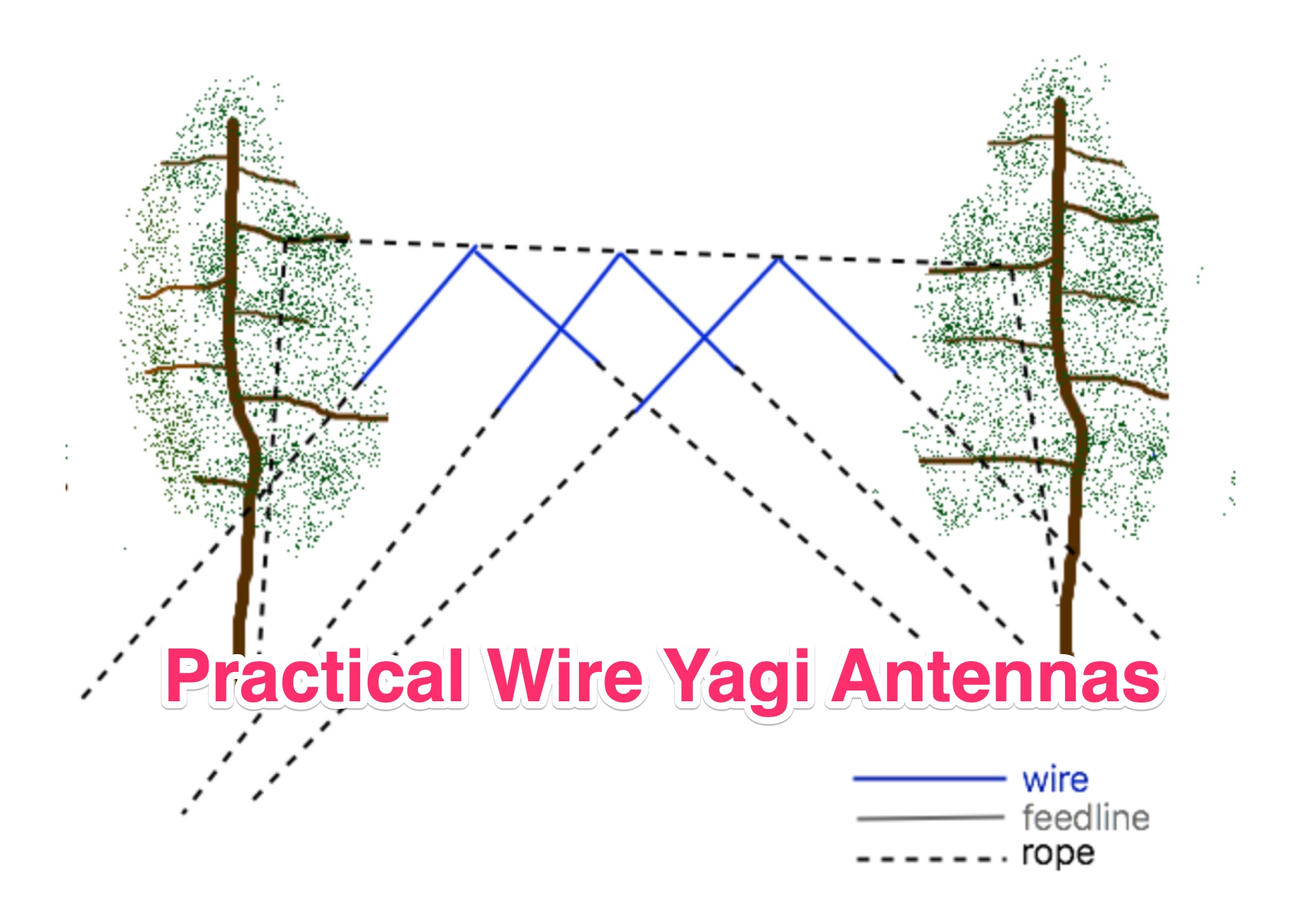 Learn how to build wire Yagi antennas for your ham radio setup. Discover how smaller wire elements can offer practical and portable options for temporary operations. Explore designs like the Hex Beam, Spider Beam, and Moxon that require less mechanical complexity and can be easily rotated or supported. Find out how to construct and hang wire Yagis from ropes, trees, or masts with inverted vees or horizontal elements. Get tips on element positioning, gain, and beamwidth considerations. Follow simple construction steps using a rope boom and marking element positions for efficient assembly. Enhance your ham radio experience with versatile wire Yagi antennas.
 -
 Constructing a double bazooka antenna for the UHF band, specifically tuned for 435 MHz, involves a straightforward process detailed with step-by-step imagery. The design leverages readily available _RG213 coaxial cable_, cut to precise lengths derived from formulas: 140.208 / F (MHz) for the radiating element and 99.06 / F (MHz) for the coaxial section. This approach yields a highly effective vertical polarization antenna, suitable for local ragchewing or repeater access. My own field experience with similar coaxial designs confirms their robustness and ease of deployment. The article emphasizes critical steps like short-circuiting cable extremities, interrupting the braid at the center, and securing an insulating support. It also covers preparing the definitive mounting with a quality feedline, noting that RG58 is acceptable for temporary use but better options exist for permanent installations. Weatherproofing is crucial for longevity, achieved through PVC electrician's tube, glue, and heat-shrink tubing. The final assembly is designed for mounting on a small aluminum mast, with the feedline routed internally. The reported SWR measurement is very satisfactory, showing approximately **+/- 3%** HF return, indicating excellent impedance matching at the target frequency.
 -
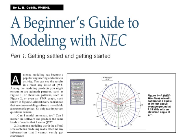 Antenna modeling is an essential technique for both amateur and professional engineers, enabling precise analysis of antenna performance. This guide, published on 4 different QST articles by L. B. Cebik, introduces NEC-2, a widely used public domain software for modeling antennas, focusing on its capabilities and practical applications. The series aims to demystify the modeling process, providing foundational knowledge and techniques for effective antenna design. Key concepts include understanding the method of moments and the importance of segmenting antenna elements. By mastering these principles, users can enhance their comprehension of antenna behavior and optimize their designs for improved performance.