Search results
Query: phasing system
Links: 7 | Categories: 0
-
 How to calculate "phasing line" lengths that actually work.
 -
 About beverage antennas, Enhanced F/B Beverages, Bandwidth of Directivity, arrays. This article describes two phasing systems for Beverage antennas that improve directivity and cancel rearward signals. These systems use lossy elements and require minimal components to achieve broadband performance.
 -
 Demonstrates the construction and implementation of a **two-element phased vertical array** for 40 meters, utilizing _Christman phasing_ techniques. The author, W4NFR, details the process from building individual 1/4-wave aluminum verticals to integrating them into a phased system. The resource covers antenna spacing of 32 feet, elevated radial design, and the critical steps for tuning each vertical to achieve a 1.1:1 SWR before combining them. It also provides insights into calculating precise coax lengths for feedlines and the phasing delay line, emphasizing the use of an MFJ-269 Antenna Analyzer for verification. The finished system exhibits good front-to-back nulls, with an overall SWR ranging from 1.6:1 to 2.2:1, which is managed by an antenna tuner. The project includes detailed photos of the relay box, showing 12 VDC relays capable of handling 5KV, and the control box in the shack for switching between three different antenna pattern configurations. Static bleed-off chokes are incorporated for protection, and the construction emphasizes robust weatherproofing for outdoor elements.
 -
 Antennas, Standard Delay Line Systems, Crossfire Phasing or Hybrids
 -
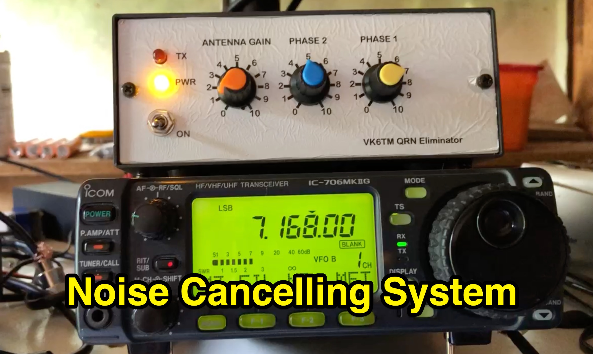 Learn how to improve reception on the hf bands by setting up a noise cancelling system that nulls out local interference. This article describes a system using a 'Main Station Antenna' to receive a wanted signal and associated QRM, and an 'Auxiliary Antenna' to pick up unwanted interference. Gain and phasing controls are used to reduce/remove interference, leaving only the wanted signal. Tips are provided based on the author's personal experience, applicable to commercial noise cancelling products, kit form, or homebrew setups. Discover the importance of configuring the 'Auxiliary Antenna' to optimize your system and improve readability of wanted stations.
 -
 Details the installation and operation of the DX Engineering TFS Series Transmit Four Square System Phasing Units, specifically models like the DXE-TFS4-160B, DXE-TFS4-80B, and DXE-TFS4-40B. It covers system components, required parts, and a discussion of vertical antenna selection, including a table of suitable DX Engineering Monoband Vertical Antennas. Installation procedures are outlined, encompassing site selection, four square layout, topographical considerations, and noise source mitigation. Specific instructions are provided for mounting the phasing unit, antenna feedline connections using 1/4-wave 75-ohm coaxial cables, and control wire routing. The document also includes details on radial system implementation, with a table of radial wire lengths for 160, 80, 75, and 40 meters, and procedures for tuning the vertical antennas for optimal performance. Operational aspects of the Four Square Control Console are described, including front and rear panel functions, control logic (Table 4), and typical transceiver/amplifier interconnections. The system enables directional control with approximately 5 dB gain over a single vertical element in four directions or an omni-directional pattern, achieving typical front-to-back ratios exceeding 20 dB. Lightning protection and initial system testing are also addressed, along with a 5 kW CW and 10 kW PEP SSB power rating and hot switching lockout feature.
 -
 DF6QV's 4-Square antenna analysis begins with a two-element array simulation, demonstrating azimuth and elevation plots for various phase differences, including a 75-135 degree range. The document then delves into the core components of a 4-Square system, such as radiators, couplers, phasing lines, and ground systems, referencing W1HKK's 1965 QST article on an 80m phased array. It explores the influence of ground conditions and element spacing on antenna performance, presenting EZNEC analysis for an 80m 4-Square with an elevated radial, showing how gain and beamwidth vary with spacing. Various 90-degree couplers, including the 3 dB hybrid coupler and the Reed Fisher coupler, are analyzed using LTSpice, detailing power splitting, phasing, and bandwidth characteristics. The resource quantifies power, voltage, current, and losses within a 4-Square system, addressing relays, capacitors, inductors, radiator radial systems, and cable losses. System impedance, bandwidth, SWR, isolation, and mutual coupling are discussed with practical construction aspects covering common mode chokes, phasing boxes, and remote control systems. Field test observations for 40m 4-Square antennas are included, with specific examples from DXpedition operations like 5A7A and VP6DX, providing real-world context to the theoretical and simulated results.