Search results
Query: rtl sdr receiver
Links: 16 | Categories: 0
-
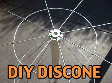 A DIY discone antenna project made to improve receiveing performance of an RTLSDR receiver.
 -
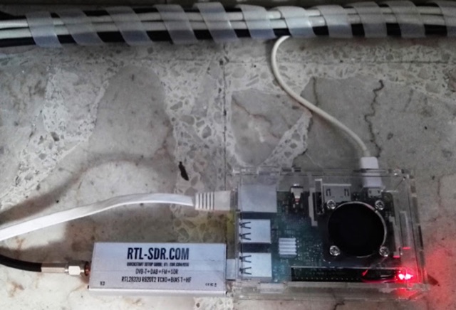
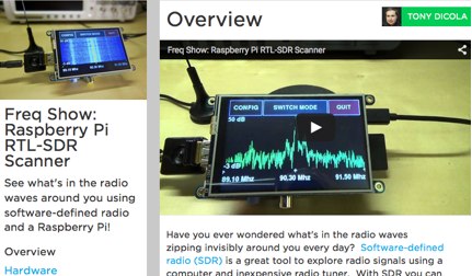 Get started with SDR using a Raspberry Pi and inexpensive RTL-SDR tuner.
 -
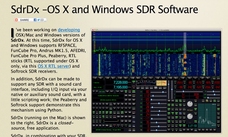 OSX/Mac and Windows versions of SdrDx. Supports RFSPACE, FunCube Pro, Andrus MK1.5, AFEDRI, FunCube Pro Plus, Peaberry, RTL sticks (RTL supported under OS X only, via this OS X RTL server) and Softrock SDR receivers.
 -
 Dodgy plans to make Archimedean spiral antenna for RTLSDR software defined radio receiver. Made of two equal lengths of coaxial cable seems to be the easiest circularly polarized antenna to make that will cover a broad range of the rtlsdr dongles E4000 tuners
 -
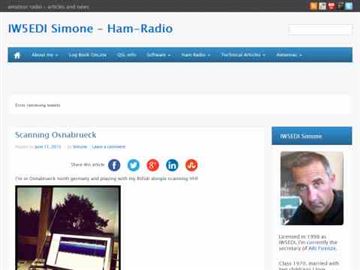 How to run an SDR Receiver on the Android Google Nexus 7 using SDR Touch App and an RTL-SDR dongle, review and costs by IW5EDI
 -
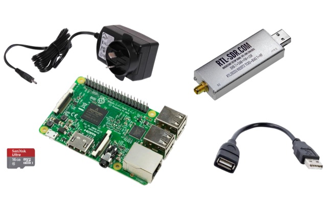 This project is a Software Defined Radio Receiver. It has a frequency range of 24MHz 1.2GHz. It can demodulate AM, FM, USB, LSB with selectable bandwidths of 600, 2400, 2800, 3200 and 6400Hz. Using a simple RTL-SDR Dongle and Raspberry Pi 3 computer using GNU RADIO
 -
 Amateur radio products,wire and yagi antennas, SDR Receivers, upconverters, pre-amplifiers, towers and RTL funcube dongles by CT1FFU
 -
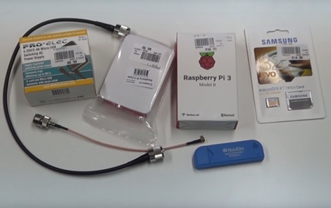 How to receive automatically NOAA wather satellite images with a Raspberry Pi and a RTL SDR. This project requires a Raspberry Pi 3 Model B a common NooElec SDR Dongle and a QFH Antenna in the attic. Article explains how to setup and configure software but no instructions on antenna.
 -
 A great page about RTL-SDR and GNU Radio with Realtek RTL2832U [Elonics E4000/Raphael Micro R820T] software defined radio receiver.
 -
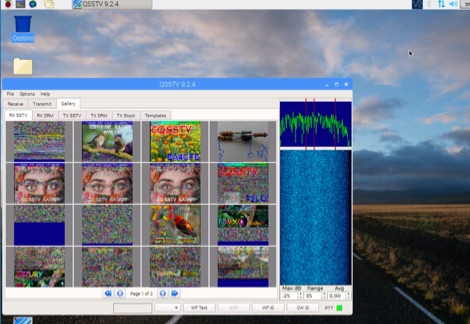 A tutorial on how to setup a receiver capable to decode SSTV signals with a small RaspberryPi version 2 and a RTL-SDR dongle. The author explains how to install the needed software to interface the RTL-SDR and a step by step guide to install the QSSTV software used to decode the signals.
 -
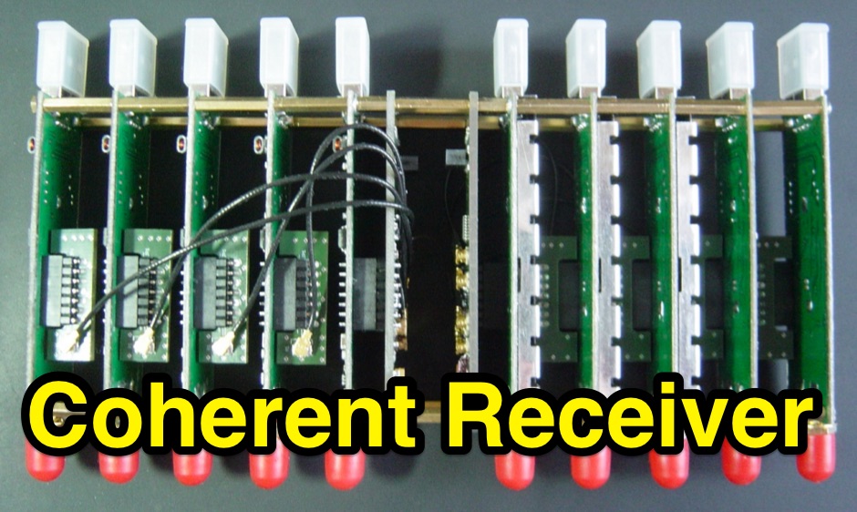 N-channel scalable coherent receiver that employs the RTL-SDR technology in order to create inexpensive multi-channel receiving systems.
 -
 Tutorial- WSPR receiver with Raspberry Pi and RTL-SDR
 -
 This project focuses on testing and comparing various antennas for receiving ADS-B (Automatic Dependent Surveillance-Broadcast) signals, utilizing software tools like RTL1090 and Virtual Radar with an RTL-SDR dongle. The goal is to evaluate the reception range ("ReceiverRange") and performance of different antenna types when tracking aircraft signals, particularly around the Amersfoort area. The project includes a comprehensive photo album documenting the antenna designs and setup processes, serving as a valuable resource for enthusiasts building ADS-B reception systems
 -
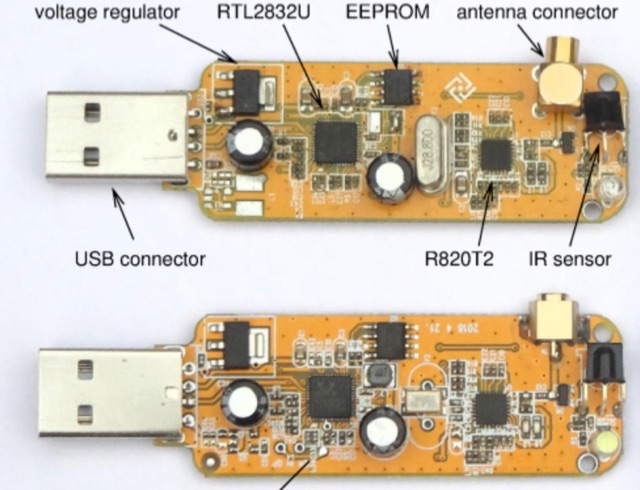 Since 2012, the RTL-SDR is the simple and cheap way to give Software-Defined Radio a try. For about 25 euro you get a receiver covering much of the VHF and UHF range, and by either adding an upconverter, or using the direct sampling option, also the HF bands. They are so cheap because they are mass-produced as DVB-T receivers.
 -
 The RTL-SDR tuner dongle is a popular tool for amateur radio enthusiasts, transforming a $10 device into a wide-band software-defined radio. This guide outlines using the RTL-SDR as a full-band pan-adapter for conventional receivers, focusing on hardware setup and software integration with HDSDR. Future sections will address RTL-SDR performance compared to native receivers, enhancing digital mode operations with virtual serial ports and audio cables.
 -
 The article discusses the construction of a UHF band-stop stub filter to protect an APRS receiver from potential damage during a balloon launch. The author, who communicates using a 441 MHz transmitter, needed to ensure that the RTL-SDR dongle receiving at 144 MHz wouldn't be damaged by the transmissions. The solution involved creating a quarter-wavelength open stub filter using coaxial cable, which attenuates the 441 MHz signal while allowing the 144 MHz signal to pass through. The filter's design is based on the principles of constructive and destructive interference, with careful measurement and trimming to achieve the desired frequency response. The final filter provided 34.8 dB of insertion loss at 441 MHz and minimal loss at 144 MHz, effectively protecting the receiver.