Search results
Query: s-meter
Links: 14 | Categories: 0
-
 A Kenwood R-5000 communications receiver located in Salt Lake City that you can remotely control and receive S-Meter readings and audio from via a web browser.
 -
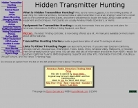 Lots of information of hidding transmitters, building portable yagi antennas, s-meters, and much more
 -
 Over 45 years of amateur radio experience inform the homebrew projects detailed on this personal website, with a particular focus on microwave frequencies. The site showcases a 24 GHz transverter and a more recent 47 GHz transverter, demonstrating practical construction techniques for extreme high-frequency operation. These projects often involve custom circuit design and careful component selection to achieve stable performance at millimeter-wave bands. Key projects include a _harmonic converter_ for frequency measurement and a tracking spectrum analyzer, essential tools for microwave experimenters. The site also documents a CW sidetone generator and a TX/RX sequencer, illustrating fundamental building blocks for radio equipment. Details on a digital frequency meter and an S-meter/dBm meter provide insights into test equipment construction. Specific achievements, such as a **24 GHz** tropo QSO with DK3SE in 2021, highlight the operational success of these homebrewed systems. The content reflects a long-standing dedication to self-sufficiency in amateur radio, providing practical examples for those interested in building their own gear.
 -
 Operating the _Icom IC-746_ HF/VHF transceiver often presents specific technical questions, and this resource compiles a comprehensive Frequently Asked Questions (FAQ) document in an ASCII text format. It details common inquiries and solutions related to the rig's functionality, accessories, and potential modifications. The content is structured into distinct sections addressing general information, power supplies, antennas, microphones, keyers, amplifiers, TNC integration, and optional IF filters. The FAQ provides practical guidance on topics such as configuring the internal automatic antenna tuning unit (ATU), selecting appropriate power supplies, and understanding microphone pin-outs. It also delves into advanced subjects like computer control via CI-V, wiring for PSK31 operation, and troubleshooting common issues like low S-meter readings on 2m FM or loose tuning shafts. Specific questions cover the installation of optional IF filters, comparing Inrad versus Icom filters, and optimizing filter combinations for various modes. Furthermore, the document outlines various hardware and firmware modifications, including those for increasing monitor volume, replacing LCD driver transistors, and implementing a "poor man's TCXO." It even touches upon untested modifications, such as replacing PIN diodes in the demodulator. The FAQ also lists manual errata and discrepancies, offering a robust knowledge base for IC-746 owners seeking to optimize their station or resolve operational challenges.
 -
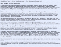 Two receivers compared, Drake R8A and Palstar R30
 -
 The RBN S-Meter visualizes real-time HF propagation data from the Reverse Beacon Network (RBN). It processes thousands of automated spots per hour, providing a real-time picture of active RF paths on HF bands. Users can set their vantage point using _Region Mode_ or _Grid Square Mode_. Region Mode allows selection from broad geographic areas like E. North America or Europe, while Grid Square Mode uses a Maidenhead grid square and radius for more precise data. The app displays eight region panels, each with horizontal bars for bands 160m through 6m, indicating signal strength with a color ramp from green to red. A dimmer trail shows peak hold values, and an S-unit readout provides additional detail. The app is a free web application accessible on any device, offering a practical tool for ham radio operators interested in CW, RTTY, and FT8 signals. It features a Progressive Web App installation option for enhanced usability on mobile and desktop platforms. Users can install it on Android, iOS, and Windows devices, providing a native app-like experience. The app replaces the previous Windows standalone executable, incorporating user feedback to improve features like grid square mode and automatic location detection.
 -
 A 0-30 MHz step attenuator, constructed from switchable Pi attenuation pads, provides a practical tool for evaluating receiver sensitivity and calibrating S-meters. The design utilizes readily available 5% tolerance resistors, with values derived from paralleled components to achieve specific attenuation steps. A schematic (Fig 1) illustrates the circuit, including PCB pad shielding, while a table details required and actual resistor values, along with percentage differences. Measurements of voltage input versus output at various frequencies are used to calculate dB attenuation, presented in a graph (Fig 4). The resource includes formulas for determining output voltage from a known input and a comprehensive 0-40 dB voltage multiplier table, which is crucial for precise signal level management. The project also references external attenuator calculators and equations for further study. Photos (1-3) provide visual guidance for the assembled unit, showing bottom, top, and front views. The project emphasizes the use of **Pi attenuation pads** and **receiver sensitivity** evaluation, offering a hands-on approach to RF signal management.
 -
 A simple superheterodyne receiver (3.5–30 MHz) for amateur radio achieves stable SSB-CW reception using modern BJTs, an AD831 mixer, a 6-pole quartz filter, and Seiler oscillators. Designed with high IF (4.5 MHz), compact AM-FM variable capacitors, and modular resonant circuits, it ensures selectivity, image rejection, and stable tuning. Built in a copper-lined wooden case, it features practical assembly techniques but lacks advanced features like AGC or S-meter. Effective on basic antennas, it achieves global reception.
 -
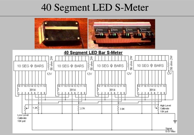 Provide your radio with a very string signal, then adjust the HIGH LEVEL pot to the threshold of illuminating the last LED (all LEDs on).
 -
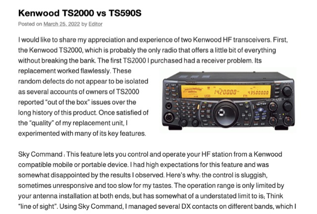 The Kenwood TS-2000, often dubbed a "Swiss Knife" transceiver, integrates HF, VHF, and UHF capabilities, but its operational compromises, such as a noisy cooling system and a cluttered user interface, led to user dissatisfaction. The author noted the TS-2000's cooling fans frequently operated at two loud speeds, making extended listening unpleasant, and observed a cluttered internal layout hindering airflow. Conversely, the Kenwood TS-590S, a dedicated HF transceiver covering 160m through 6m, offers a significantly quieter operation due to two variable-speed cooling fans and a more spacious internal component layout. Its front LCD display features larger characters and improved backlighting, enhancing readability. The TS-590S also boasts an 18-band audio equalizer, eliminating the need for external audio processing equipment like the _W2IHY EQplus_, and a built-in USB port for seamless CAT control and digital mode operation, a notable upgrade from the TS-2000's legacy serial ports. Performance-wise, the TS-590S demonstrated a perceived **+6 dB** signal increase on the S-meter compared to the TS-2000, and superior reception of weak, near-noise-level signals. Its comprehensive filtering, including effective bandpass and notch filters, along with improved noise blanker (NB) and noise reduction (NR) capabilities, allows for better signal isolation and interference mitigation, even outperforming an external _MFJ-1025_ noise suppressor in some reported cases.
 -
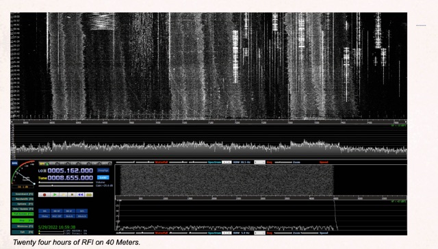 Demonstrates the application of Software-Defined Radios (SDRs) as effective tools for conducting Radio Frequency Interference (RFI) site surveys. The resource details the methodology for capturing and analyzing RFI, specifically focusing on the 80-meter band over a 24-hour period. It outlines the setup of an SDR-based survey tool, utilizing software like _S-Meter Lite_ and _Spectrum Lab_ to visualize and quantify noise sources. The article emphasizes the SDR's wideband capabilities, which allow for comprehensive identification and documentation of RFI across broad frequency ranges, crucial for effective mitigation strategies. The analysis presents practical results, illustrating how continuous monitoring can reveal intermittent RFI sources that might otherwise go undetected. For instance, the survey identified noise peaks exceeding **S9+20dB** on 80 meters during specific hours, correlating with local appliance usage. The methodology provides a repeatable process for hams to characterize their local noise floor, enabling targeted RFI suppression efforts and improving weak-signal reception, particularly for DXing and contesting.
 -
 A versatile digital VFO design utilizing the Silicon Labs Si5351a oscillator chip and Nokia 5110/3310 graphics LCD display, operating from 1-160MHz with dual VFO capability. This microcontroller-based system, powered by an ATmega328 processor, features rotary encoder tuning, selectable step sizes, RIT control, and comprehensive band memory functions. Drawing less than 40mA at 3.3V, it significantly improves upon previous DDS designs' power consumption while offering advanced features like S-meter display, VFO lock, and programmable BFO/CIO offsets. The design achieves flexible functionality through simple hardware implementation and efficient software architecture, making it particularly suitable for QRP and portable amateur radio applications.
 -
 This project features a compact, 5-LED general-purpose S-Meter, designed for use with various radio circuits. It utilizes the LB1403 IC, with alternatives like LB1413, LB1423, and others. The circuit's design allows flexibility, with one version featuring a trimpot for calibration and another without it for more compact setups. The LB1423 is preferred for its low current draw and dB-calibrated scale. This S-Meter offers an efficient, customizable solution for measuring signal strength in amateur radio applications. In Portuguese.
 -
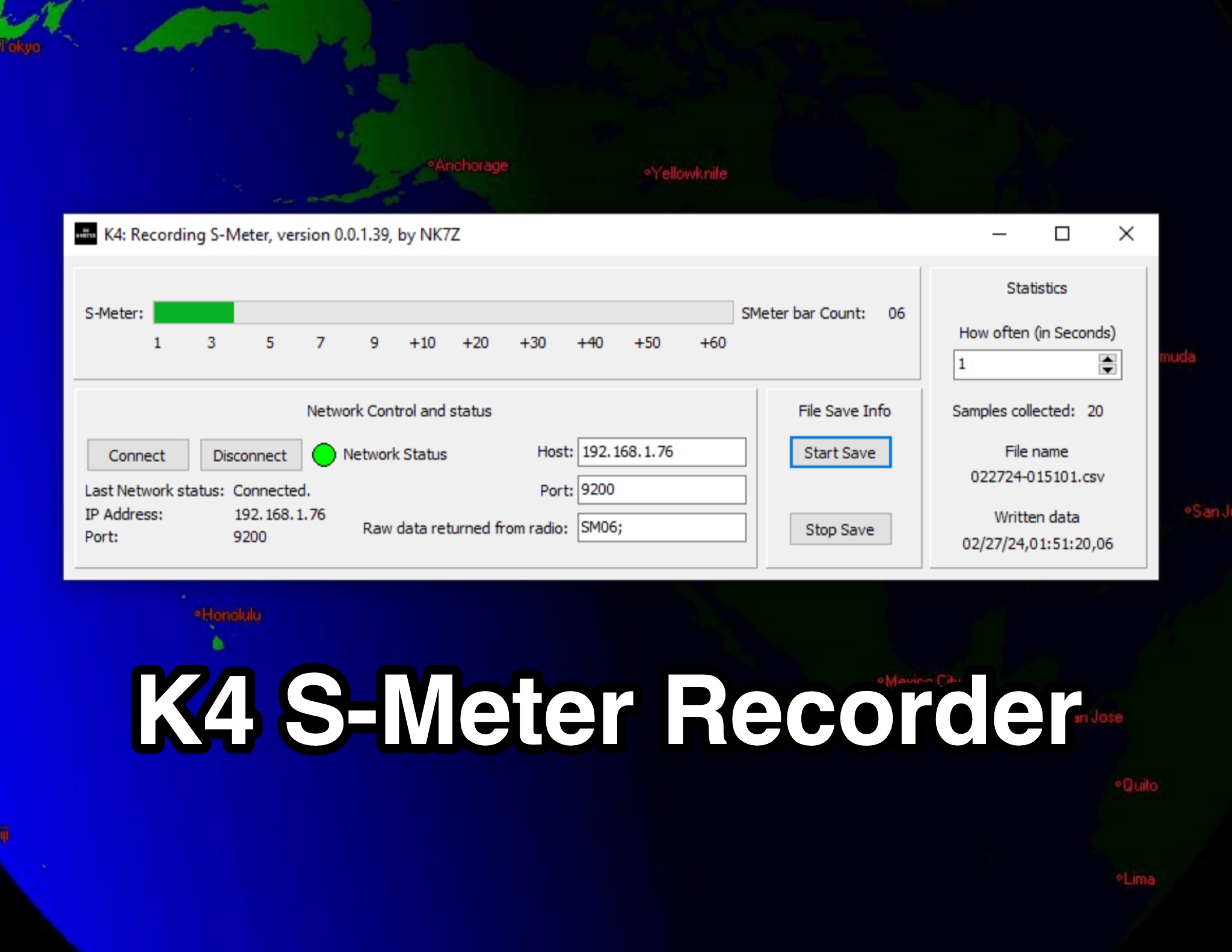 This page presents the K4 S-Meter Recorder, a tool designed for the Elecraft K4 radio by hams. The tool collects S-Meter readings and saves them to a CSV file, allowing users to create graphs of RFI over time. These graphs are valuable during RFI hunting, aiding in pinpointing the source. Visitors can view the program's interface, download it at their own risk, and subscribe to the blog for updates. The page provides insights into the K4 S-Meter Recorder's functionality and usage for ham radio operators seeking to manage RFI effectively.