Search results
Query: toroid calc
Links: 14 | Categories: 1
Categories
-
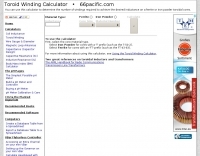 Choose Iron Powder or Ferrite and calculate required turns
 -
 End-Fed Half-Wave Antennas (EFHWAs) are analyzed for their utility in portable QRP operations, emphasizing their simplicity, efficiency, and predictable radiation patterns compared to other portable antenna types. The discussion contrasts EFHWAs with vertical antennas, random length wires, and center-fed dipoles, highlighting the common pitfalls of each, such as ground system dependency for verticals and feedline issues for dipoles. The article details the electrical half-wavelength calculation using the formula L (Ft) = 468/F(MHz) and explains how EFHWAs can be resonant on harmonic frequencies, enabling multiband operation. Various deployment configurations are presented, including the inverted L, inverted Vee, sloping wire, and vertical setups, each with specific advantages for radiation angle and polarization. For instance, a vertical EFHWA offers a low angle of radiation suitable for DX contacts without requiring an extensive ground system. The resource also addresses the counterpoise requirements, suggesting a quarter-wavelength wire or connection to a metallic structure for decoupling. A schematic diagram for a simple parallel-tuned circuit tuner, based on the _Rainbow Bridge/Tuner_ design, is provided, detailing component values for 30 and 40 meters, including a 6 microhenry toroidal inductor and a 20-100 picofarad mica compression capacitor. The tuner's adjustment process for SWR matching is also outlined.
 -
 Demonstrates the essential steps for winding **toroidal cores**, a fundamental skill for amateur radio operators engaged in homebrewing and kit building. It addresses the critical aspects of selecting the correct core material and wire gauge, emphasizing the importance of precise turn counting and consistent winding tension to ensure optimal circuit performance. The resource details methods for preparing the wire, including techniques for safely removing enamel insulation from leads using flame, sandpaper, or a solder pot, and provides guidance on tinning the exposed wire. Explains the process of mounting the wound toroid onto a printed circuit board, highlighting the need for careful lead placement and secure soldering to prevent shorts and ensure mechanical stability. It also offers a practical formula for calculating the required wire length based on the desired number of turns and the specific **toroid** size, referencing common core types like T-50 and FT-240. The guide stresses the importance of verifying the inductance of the wound component, often using an inductance meter, to confirm it matches design specifications. Provides practical tips for handling multi-filar windings and managing short lead lengths, which can be particularly challenging. It underscores the necessity of meticulous attention to detail throughout the winding and installation process to achieve reliable and efficient RF circuits.
 -

-
 Operating a ZS6BKW antenna often involves understanding its lineage from the _G5RV_ design, with specific modifications by ZS6BKW to optimize performance on several bands. Through computational analysis and field measurements, the antenna's dimensions were refined to allow operation on 10, 12, 17, 20, and 40 meters without an antenna tuner. For 80, 30, and 15 meters, a tuner is necessary, though efficiency on 30 and 15 meters is noted as not particularly high. The physical configuration consists of two 13.755-meter radiating elements fed by a 12.20-meter section of 450-ohm ladder line. Tuning the antenna on the 20-meter band is critical, and any deviation in the ladder line's characteristic impedance necessitates recalculating the element lengths. The design is also referenced in the 12th edition of _Rothammel's Antennenbuch_, page 219. Proper common mode current suppression is crucial at the transition from ladder line to coaxial cable. This can be achieved with a common mode choke, such as several turns of coax wound into a coil or over a ferrite toroid like an Amidon T130. While a 1:1 balun is an option, it may introduce issues.
 -
 Online calculators for toroid coil, air-core coil inductance, XL, XC, and more.
 -
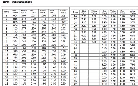 To save a little time from calculating and experime nting when winding toroid cores here a chart of the most commonly used cores
 -
 The article, "Using 75 Ohm CATV Coaxial Cable," details methods for employing readily available 75-ohm CATV hardline in standard 50-ohm amateur radio setups. It addresses the inherent impedance mismatch and practical considerations, such as connector compatibility, for hams seeking cost-effective, low-loss feedline solutions. The resource specifically contrasts common 50-ohm cables like RG-8, RG213, and _LMR-400_ with 75-ohm hardline, highlighting the latter's lower loss characteristics, particularly at VHF and UHF frequencies. It explores two primary approaches to manage the impedance difference: direct connection with an acceptable SWR compromise and precise impedance transformation. The direct connection method acknowledges that a perfect 1:1 SWR is not always critical, especially when using low-loss coax. For impedance transformation, the article explains the use of half-wavelength sections of coax to reflect the antenna's 50-ohm impedance back to the transmitter, noting its single-frequency effectiveness. It also briefly mentions transformer designs using toroid cores and a technique involving two 1/12 wavelength sections of feedline for broader bandwidth. The content further clarifies the concept of _velocity factor_ for calculating electrical versus physical cable lengths, providing a generic formula for precise length determination. It notes that while half-wave matching is practical for 10 meters and above, it can result in excessively long runs for lower bands like 160 meters, potentially adding **250 feet** of cable. The article also mentions achieving a usable bandwidth of 28.000 MHz up to at least **28.8 MHz** on 10 meters with specific transformation techniques.
 -
 Select the toroid by material type and dimension of the toroid, the desired inductance and you will get the numbers of turns
 -
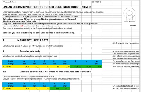 This EXCEL Program Worksheet calculates the safe operating conditons for a toroidal transformer operating between 1 and 50 MHz. Manufacturer data for complex permeability, magnetic dimensions, and saturation flux density must be available. Some core types which are commonly used in amateur transmission are included. The program produces limiting winding voltages for linear operation and temperature rise over the range of frequencies and power specified.
 -
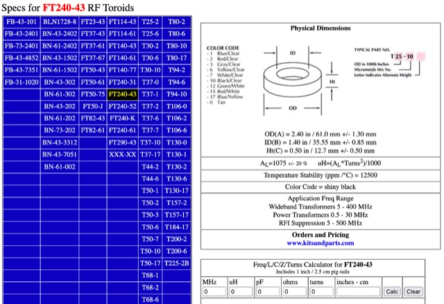 This website provide online calculator for several values about a large variety of toroids. Freq/L/C/Z/Turns Calculator, Impedance Matching Network Calculator
 -
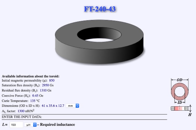
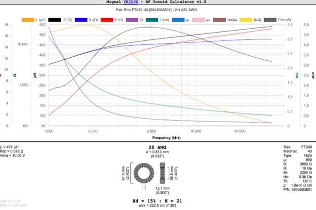 This RF Toroid Calculator provides graphical calculator used to determine the inductance and other parameters of ferrite and powdered-iron toroids. It simplifies the process of selecting the appropriate toroid for use in radio frequency (RF) circuits
 -
 Presents a detailed construction guide for a 9 dB, 70cm collinear antenna, utilizing readily available _RG58/U_ coaxial cable and PVC pipe for housing. The resource outlines the critical calculations for ½ wavelength sections at 444 MHz, incorporating the coaxial cable's velocity factor of 0.66, which yields a section length of 223 millimeters. It specifies the preparation and soldering of eight such half-wavelength sections, each cut to 231mm to allow for trimming, forming the core of the array. Further instructions detail the integration of a ¼ wave element (169mm #16 solid wire) at the top and a ¼ wave aluminum tube (160mm, 5/16 inch) at the bottom, crimped to the feed point's braid. The guide also addresses RF common mode current suppression by suggesting the use of _FT50-43_ toroids on the feedline. Final assembly steps cover mounting the antenna within ¾" PVC pipe using a wooden dowel, waterproofing connections, and initial SWR checks. The article also discusses scaling the design for different element counts and other VHF/UHF bands.
 -
 Online impedance calculators grouped by types like Wire inductances, Toroid incuctances, Plane, PAD, Strap inductances, but even Core and Coax Inductances. Air core inductances and mutual inductance groups are also availbale. All these calculators let you input specific paramenters based on the inductor selected and will calculate specific incutance and related dimensions.