Search results
Query: tower project
Links: 20 | Categories: 1
Categories
-
 The W5GI Mystery Antenna is a versatile multi-band wire antenna designed for amateur radio operators. It covers frequencies from 80 meters to 6 meters, making it suitable for a wide range of operating conditions. The antenna features a low feed point impedance, allowing for easy matching with most radios, whether or not an antenna tuner is used. Its construction is straightforward, requiring only two vertical supports approximately 130 feet apart, making it ideal for hams without towers. Users have reported excellent performance, particularly on the 20-meter band, where it outperforms similar designs like the G5RV. This antenna is unique in its design, incorporating three half waves in-phase on 20 meters, resulting in a six-lobe radiation pattern. Despite its effective performance, the antenna is challenging to model, which adds to its mystique. The W5GI Mystery Antenna has gained popularity among amateur radio enthusiasts worldwide, with many users praising its ease of construction and effectiveness. Whether you're a beginner or an experienced operator, this antenna offers a fun and rewarding project that can enhance your HF capabilities.
 -

-

-
 Technical reference about Accessories, Amplifiers, Antennas, Cable and Connectors, Filters, Geography, Grounding, Gunk, Matching Networks, Projects, Propagation Info Radios, RFI/EMI, Rotors, Station Setup, Towers.
 -
 Constructing a **2-meter** J-pole antenna from readily available copper plumbing components offers a robust and cost-effective solution for VHF operation. This design, dubbed the "Plumber's Delight," functions essentially as a half-wave dipole fed by 50-ohm coax via a **gamma match**. It incorporates a quarter-wave copper tubing support, which, when affixed to a metal mast or tower, enhances forward power in the direction of the radiating elements. The original configuration utilized a small ceramic trimmer capacitor for the gamma match, suitable for up to 10 watts. A subsequent modification replaced this with a 50 pF variable capacitor housed in a plastic enclosure, accommodating higher RF power and improving weather resistance. The antenna elements are secured using a copper "T" fitting, and an SO-239 connector mounts directly to this fitting. Performance includes gain away from the support mast, and tuning is straightforward by adjusting the gamma match capacitor for a 1:1 SWR. The total cost for materials, excluding the capacitor and coax, can be under $10.
 -
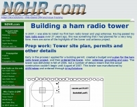 Ham Radio Tower Project at N0HR. Includes site plan, escavation, tower construction, HF antennas, grounding and lightning protection, coax and more.
 -
 JJ0DRC's HF multi-band delta loop antenna project, initially conceived during the waning peak of Cycle 23, addresses the common challenge of achieving effective DX operation from a small residential lot in Japan. Dissatisfied with a ground plane antenna's performance in SSB pile-ups, the author sought a beam-like solution without a tower, drawing inspiration from a JJ1VKL article in CQ Ham Radio Sep. 2000. The antenna, constructed in October 2000, employs two 7.2-meter fishing rods (37% carbon fiber, reinforced with cyano-acrylate glue and aluminum tape) and 1mm enameled wire, fed by an Icom AH-4 external antenna tuner. While the exact beam pattern remains unmeasured, JJ0DRC observed a significantly higher callback rate compared to dipole antennas, particularly on higher bands. The system's circumference length of 15-20m is crucial for maintaining a good beam pattern across HF bands, though performance on lower bands like 80m, 40m, and 30m becomes less directional as the length deviates from a full wavelength. Ongoing maintenance addressed degradation issues, including aluminum tape cracking and wire breakage at connection points due to strong winds (often exceeding 10-15m/s in winter). The author reinforced rod connections with IRECTOR PIPE SYSTEM components and INSU-ROCK ties, and improved wire attachment methods using Cremona rope and epoxy bond to enhance durability.
 -
-
 This project outlines the construction of a 3-element reversible quad antenna specifically designed for the 40-meter band. The materials required include pushup towers, pressure-treated posts, insulated wire, and various electrical components such as relays and a balun. The construction process is straightforward, beginning with the installation of the posts in a straight line, followed by the assembly of the antenna elements and their elevation to the desired height. The antenna's design allows for directional signal reception, making it ideal for operators looking to enhance their communication capabilities on the 40-meter band. The project includes detailed instructions on tuning the antenna for optimal performance, ensuring that operators can achieve the lowest SWR possible. Additionally, the design can be adapted for other bands by extrapolating dimensions, providing versatility for amateur radio enthusiasts. Overall, this reversible quad antenna project is suitable for both beginners and experienced operators, offering a practical solution for improving signal strength and directionality in 40-meter communications.
 -
-
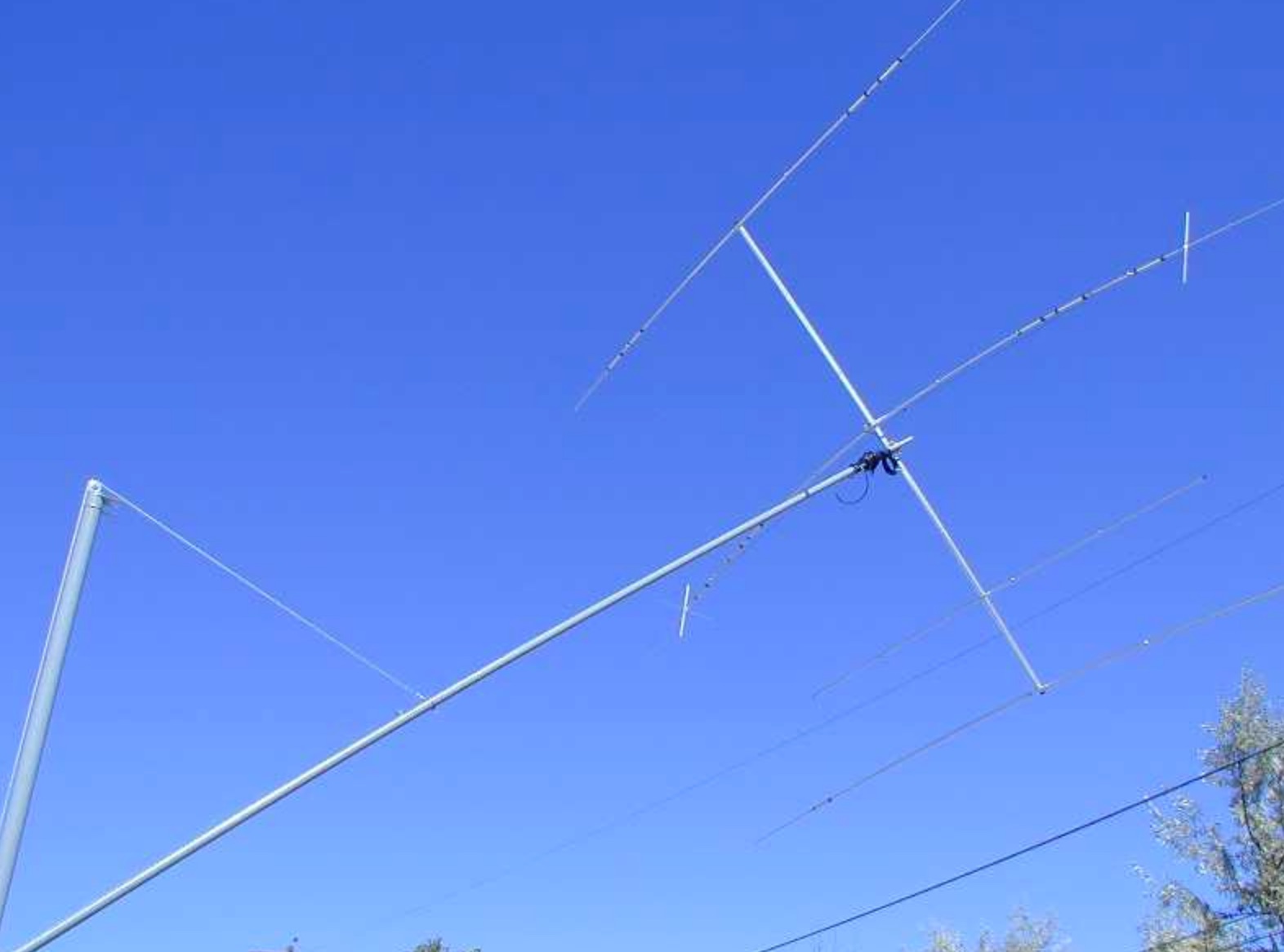
 This project details the construction of a **full-sized 40-meter vertical antenna**, born from a renewed interest in 7 MHz operation and a desire for improved effectiveness over simple dipoles. The author, K5DKZ, initially focused on VHF experimentation, which provided an inventory of aluminum tubing and fiberglass spreaders for this endeavor. Before this vertical, K5DKZ utilized an 80/40 meter inverted-vee trap dipole and a 40-meter broadband dipole, but now primarily uses a pair of full-sized, phased, quarter-wave verticals spaced 35 feet apart for serious 40-meter work. The construction involves a base-heavy design for stability, using a 44.5-inch section of 1-1/4 inch steel TV mast driven into 1-3/8 inch aluminum tubing, insulated by a 105-inch section of Schedule 40 PVC pipe. The assembly reaches 31 feet, close to the 32 feet required for a quarter-wavelength on 40 meters, with fine-tuning achieved by winding wire onto a fiberglass spreader. The design is explicitly presented as a foundation for a two-element 40-meter Yagi beam, outlining modifications like substituting aluminum for steel in the base and using an inductive hairpin match for the driven element. The article also discusses tuning considerations for a large 40-meter beam, noting the 100 to 200 kHz upward frequency shift when raised, and suggesting methods for installation on a tower. The author emphasizes the cost-effectiveness and good performance of the monopole approach, especially when multiple verticals are needed.
 -
 A cooperative venture between MSUARC and Calloway County Fire and Rescue
 -
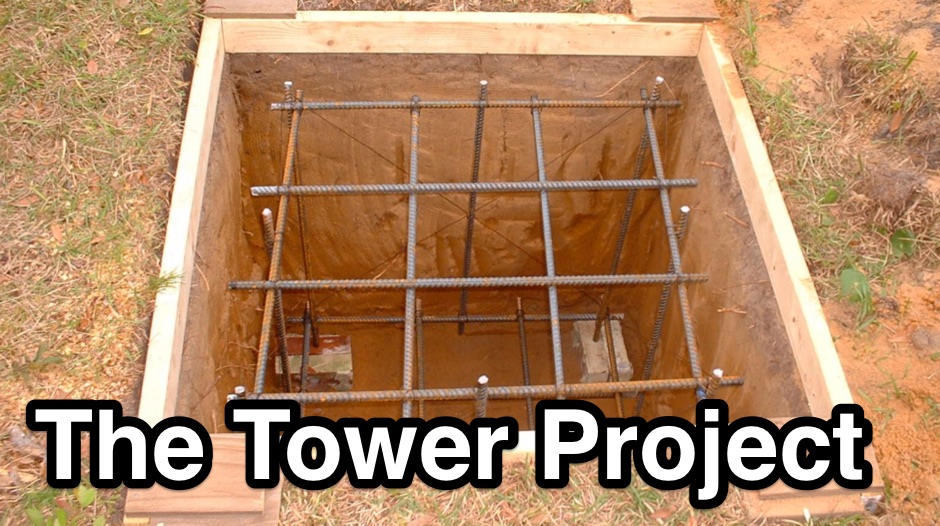
 A 38-foot Tristao Tower, similar to the U.S. Tower HDX538, was installed twice by the author, first in 1980 and then reinstalled in 1989. The resource details the challenges of self-performing heavy construction tasks like breaking concrete and digging a 3' x 3' x 6' deep footing, contrasting it with hiring professionals for the second installation. It highlights the financial and physical costs associated with DIY tower foundation work, noting a rebar cage cost of $65 in 1980 versus $150-$175 today, and the expense of tools for bending rebar. The content emphasizes the critical importance of obtaining building permits, recounting how a permit in Buena Park, California, nullified a neighbor's complaint about TVI. It also discusses the necessity of adhering to local building codes, such as the 1975 UBC and the subsequent 1985 UBC recertification requirement, which reduced the allowed antenna wind loading from 30 square feet to 20 square feet for the author's _KT34A_ Yagi. The footing depth also increased from 6 feet to 6.5 feet under the newer code. Practical advice includes hiring licensed contractors for specialized work, delaying antenna installation for a month after raising the tower, and verifying buried utilities before any excavation. The author provides specific examples of utility location services like _DigAlert_ in California, underscoring the legal and safety implications of neglecting this step. The narrative is grounded in personal experience, offering a realistic perspective on tower projects.
 -
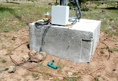
 This is a description of how KO4BB built his tower. It is provided in the hope that it will be useful to anyone want to setup his own ham radio tower.
 -
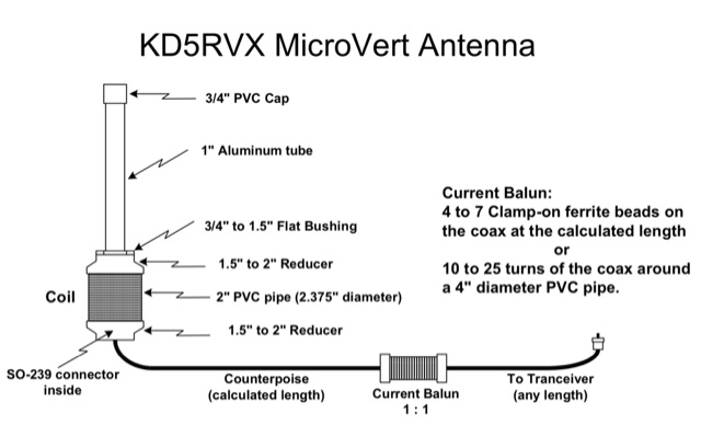 A Microvert antenna by KD5RVX based on the original microvert concept by DL7PE. PDF includes a 20 foot portable PVC tower project
 -
 Describes Atlantic Tower Services (ATS), a company specializing in antenna tower erection and maintenance, operating from Orlando, Florida. ATS offers a range of services including site maintenance, structural repairs, system modifications, and complete tower installations for various communication needs. The company emphasizes its capability to handle diverse tower projects, from routine inspections to complex upgrades, ensuring structural integrity and optimal performance for amateur radio and commercial installations. ATS focuses on delivering reliable infrastructure solutions, supporting the backbone of communication systems. Their service portfolio covers critical aspects of tower ownership, addressing both preventative care and reactive solutions for existing structures. They are equipped to manage projects involving different tower types and heights, adhering to safety standards and operational best practices. Services include **site maintenance** and _structural modifications_.
 -
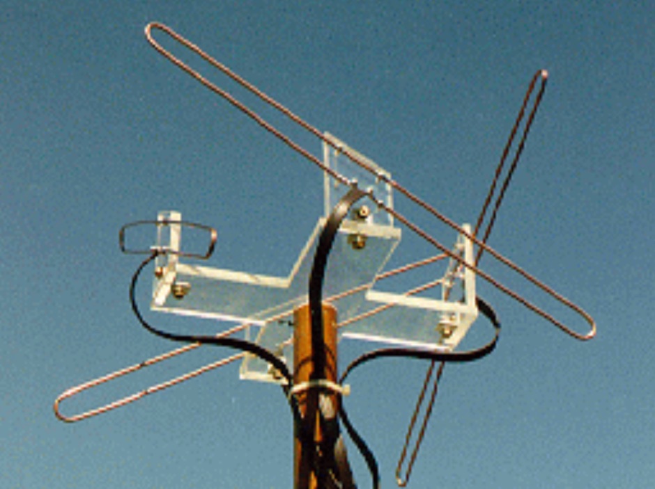 This Antenna project is a bit more complex than other omni antennas for satellite use, but it is much easier and cheaper than a standard tower mounted circular polarized azimuth and elevation rotating beam system.
 -
 A tower grounding project using copper tubing to help protecting an antenna tower by WD0M
 -
 A Tower Project at WOIVJ. A pictorial story of the erection of a 40 foot, self-supporting, fold-over tower.
 -
 Building an 80-160 meter antenna in a small garden (9m x 14m) involves creative solutions due to space constraints. This project outlines the construction of a trapped 80-160 meter vertical dipole, utilizing a crank-up tower and an 11-meter fiberglass pole. The design prioritizes minimal visibility, ease of construction, and cost-effectiveness, achieving effective operation despite limited space.