Search results
Query: 10 meter net
Links: 127 | Categories: 0
-
 A trapped dipole antenna based on the orignal W3DZZ antenna design resonating on 80 40 20 15 10 meters
 -
-
 Accurately determining an antenna's feedpoint impedance is crucial for optimal performance, especially when experimenting with new designs or making adjustments. While SWR meters provide basic information, a full complex impedance measurement reveals the resistive and reactive components, which are essential for proper matching. Modern antenna analyzers, like the _Palstar ZM30_ or MFJ259B, simplify this task, but measurements taken through a transmission line require careful interpretation due to impedance transformation. This resource details a calibration method to precisely account for the effects of the feedline. It explains how a transmission line can significantly alter the measured impedance, illustrating this phenomenon with a Smith Chart example where an 80m antenna's [22 + j6] Ohms feedpoint impedance transforms to [82 + j45] Ohms after a 10m line. The guide demonstrates using a transmission line calculator applet, such as the one by W9CF, to reverse this transformation. It outlines the process of calibrating a specific length of RG174 coax, showing how an initial 26ft estimate was refined to **25.85ft** to accurately predict a known 22 Ohm load, significantly improving accuracy over uncalibrated results.
 -
 Cushcraft X7 20-15-10 Meter 7 element beam Assembly & Installation
 -
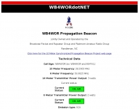 WB4WOR Propagation Beacon on 6 and 10 meters Jointly Owned and Operated by the Broadcast Packet and Repeater Group and Piedmont Amateur Radio GroupRandleman, NC USA
 -
 Presents a QRP AM/CW transmitter project specifically designed for the 10-meter band, utilizing a crystal oscillator and a collector-modulated AM oscillator. The design employs a 2N2219(A) transistor in a Colpitts configuration, generating 100 to 350 mW of RF output power depending on the 9-18 Volt supply voltage and modulation depth. Frequency stability is maintained by a 28 MHz crystal, with fine-tuning possible via a Ct1 trimmer capacitor for approximately 1 kHz adjustment. The resource details the RF oscillator stage, implemented with a 2N2219 NPN transistor, emphasizing frequency stability and low power dissipation. It also covers the amplitude modulation stage, managed by a 2N2905 PNP transistor, which impresses audio information onto the carrier. Selective components (C3, C4, C7, C5) enhance voice frequencies within a +/- 5 kHz bandwidth, and modulation depth is controlled by R2 and R3. The project includes a 3-element L-type narrow bandpass filter (Ct3, L3, C10) to suppress harmonics and ensure a clean output signal. The project provides a complete schematic diagram, a comprehensive parts list including specific capacitor, resistor, and inductor values, and construction notes for the coils (L1, L2, L3). It also offers practical advice on enclosure requirements, suggesting an all-metal case or a PVC box with graphite paint for RF shielding. Operational parameters such as current draw (27mA@9V to 45mA@16V) and input impedance (50 Ohms) are specified, alongside guidance on antenna matching and the importance of a valid amateur radio license for 10-meter band operation.
 -
 A magnetic loop antenna working from 30 to 15 meters with 100W
 -
 A fractional bandwidth of up to 30:1 characterizes spiral antennas, making them highly effective across a very wide frequency range, often from 1 GHz to 30 GHz. The resource details two primary types: the **Log-Periodic Spiral Antenna** and the **Archimedean Spiral Antenna**, defining each with specific polar functions and illustrating their planar configurations. It explains that spiral antennas are typically circularly polarized, with a Half-Power Beamwidth (HPBW) of approximately 70-90 degrees, and a peak radiation direction perpendicular to the spiral plane. The content elaborates on critical design parameters affecting radiation, including the total length (outer radius) for lowest frequency, the flare rate ('a' constant) for optimal radiation versus capacitive behavior, the feed structure (often an infinite balun) for high-frequency operation, and the number of turns (typically 1.5 to 3 turns). It also discusses the theoretical impedance of 188 Ohms for Log-Periodic spirals, derived from Babinet's Principle, noting actual impedances are often 100-150 Ohms. The article presents a simple construction method for an Archimedean spiral, demonstrating VSWR and efficiency measurements. Measurements from a constructed spiral antenna show a VSWR that is fairly constant across the band, albeit with a mismatch loss of about 3 dB. The antenna efficiency remains around -5 dB (31.6%) across its operating range, indicating a decent wideband radiator despite opportunities for optimization.
 -
 The grounded half loop describe in this article is basically a half wave length wire on 80 Meters. The 80M grounded half loop antenna, inspired by a 1984 QST article by SM0AQW, is a compact solution for limited spaces. Comprising a 127-foot wire fed against ground and supported by radials, it balances performance and practicality. Despite compromises in length and proximity to structures, the antenna delivers strong signal reports and effective multi-band tuning using an SGC 237 antenna coupler. Ideal for CW operation, it offers low SWR on 80-10M, though noise levels and safety considerations warrant attention. This versatile design excels in constrained environments.
 -
 A monster magnetic loop antenna for 160 meters band. This Magnetic loop is optimized for 1840 Khz + 50 Khz. PDF Article published on La Radiospecola 10.22
 -
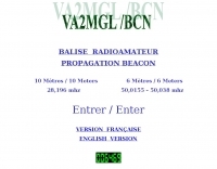 Info and specifications on my three beacons on 10 and 6 meter bands. You will find also informations on the propagation for these two band.
 -
 An home made magnetic loop antenna project using a military surplus 150pf capacitor by KF5CZO
 -
 10 meter propigation beacon project
 -
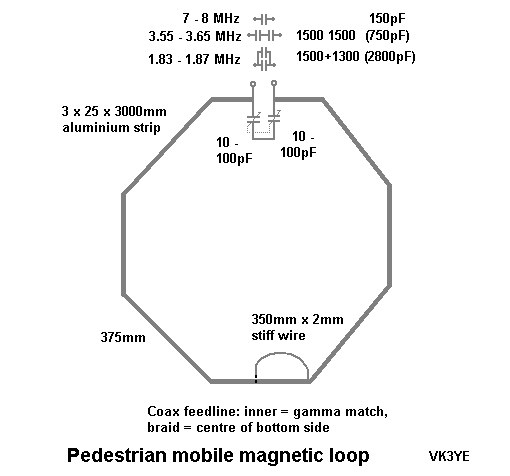 A magnetic loops for HF pedestrian mobile project by VK3YE
 -
 Demonstrates various practical amateur radio projects and technical discussions through video episodes. One episode details cutting and retuning a _1/4 wave shorted stub_ from 101.7 MHz to 107.5 MHz to safeguard a transmitter's driver stage, alongside insights into advanced _160-meter antenna systems_ like eight-circle arrays and beverage antennas. Another segment covers upgrading firmware on an _ATS-20+_ receiver using AverDudes for improved display and functionality, and a detailed guide on using D-Star DR mode on an _ICOM ID-52A_ for international repeater programming. Additional content includes a deep dive into _OpenHamClock_ as a potential replacement for the HamClock project, updates on _Raspberry Pi 5_ running Trixie OS, and a review of the Choyong LC90 Internet radio with AI integration. The series also features "Ham College" episodes, which meticulously prepare viewers for the Technician Exam by covering topics such as antenna and transmission line measurements, SWR interpretation, and the functions of basic electronic components like rectifiers, relays, and transistors. Practical advice on coaxial cable characteristics, dummy loads, and proper soldering techniques is also provided.
 -
 A multiband coax trapped dipole for 10-80 meters bands by DF1PU
 -
 A system designed to automatically tune small transmitting magnetic loop antennas, particularly beneficial for **contest operations** where rapid frequency changes are common. The core of the system involves a PC-based control application, AutoCap, written in C#, which monitors antenna SWR via an external meter and commands a motor interface to adjust the loop's variable capacitor. The software is compatible with Windows and Linux via the Mono framework, offering a graphical user interface for monitoring system status, SWR, power, and motor commands. Key components include one or more magnetic loop antennas equipped with DC or stepper motors for capacitor adjustment, an SWR meter with data output (such as the Telepost LP-100A or a homebrew serial/USB SWR meter), the AutoCap PC software, and a motor interface. The most effective motor interface utilizes an **Arduino-based controller** with custom firmware, providing precise control over both simple DC motors and stepper motors, and supporting features like motor braking for finer adjustments. The system allows for configurable SWR thresholds, pulse widths, and motor effort settings to optimize tuning speed and resolution. Optional radio integration provides frequency hints, enabling the algorithm to learn the relationship between motor actions and resonant frequency, thereby speeding up initial tuning responses. The software also supports antenna profiles, allowing operators to save and recall specific configurations for different loops, including accumulated frequency hint data.
 -
 In this experiment the autor is going to explore the use of a 1:64 matching network on the End Fed Long Wire Antenna. Experiment will consist in build a 80-40-20-15-10 meter End Fed Long Wire Antenna with a 1:64 matching network from the documentation available on the internet
 -
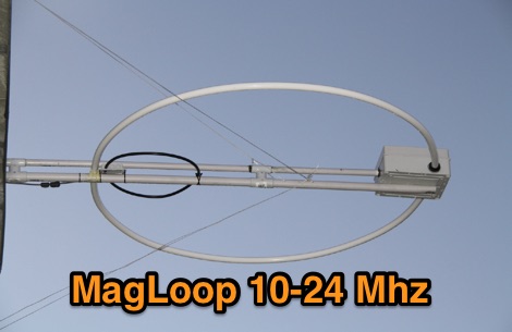
 Schematic diagram and description of a magnetic loop antenna that works from 10 to 20 meters band, made from junk
 -
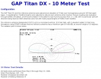 GAP Titan DX 10 15 20 40 meter performance tests by AA3RL
 -
 A frame antenna for the 80 meters band, built to be folded and to be easy to be mounted and dismounted. This antenna is suitable for indoor and QRP use, bandwidth is just 10kHz and should be observed a proper distance while transmitting due to high voltage.
 -
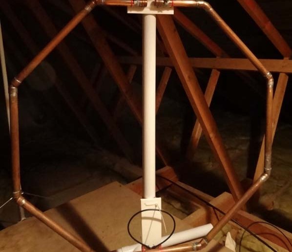 Octagonal magentic loop antennas that work from 20 to 10 meters with pictures and efficiency reports by G1KEA
 -
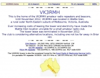 Running 10 and 6 meters beacons, 6 m and 70 cm fm repeater from Melbourne, Australia
 -
 A few pictures of an homebrew magnetic loop RTX antenna project, working from 30 to 12 meters with excellent results
 -
 KB9AMG's Top WSPR Spots presents a focused online tool for monitoring **2-way WSPR reports**, specifically detailing propagation data from February 2026 through March 2026. This resource aggregates _WSPRnet_ data, allowing radio amateurs to observe weak signal propagation conditions across various bands. The interface is straightforward, presenting callsigns, frequencies, signal-to-noise ratios, and distances for each reported contact, which is crucial for understanding current band openings and signal paths. The utility of this WSPR spotter lies in its ability to quickly visualize global propagation. Users can identify active stations and assess signal viability over long distances, with reports often showing contacts spanning thousands of kilometers. For instance, a typical WSPR report might indicate a signal from Europe reaching North America with a _SNR_ of -25 dB, demonstrating effective low-power communication. This data is invaluable for planning DX operations or evaluating antenna performance under actual propagation conditions.
 -
 Presents a concise guide for Amateur Radio operators participating in Jamboree-on-the-Air (JOTA), an annual event connecting approximately 500,000 Scouts and Guides worldwide via ham radio. The resource details how to initiate a voice contact, including the use of "CQ Jamboree JOTA" and proper signal reporting with the RST system. It also outlines the typical exchange information, such as name, QTH, Scout rank, and age, encouraging participants to practice their responses. Authored by Bill Wetherill, N2WG, the brochure provides a practical phonetics chart and a comprehensive Morse code dictionary, including punctuation and prosigns like AR and SK. It clarifies rules for third-party operation under the direct supervision of a licensed operator, noting restrictions on international contacts without specific government agreements. Additionally, the guide lists recommended World Scout Frequencies for SSB and CW across 80, 40, 20, 17, 15, 12, and 10 meters, emphasizing courteous operating procedures. It includes a section on common Q-signals like QRM, QRN, and QSL, alongside the Amateur's Code, which stresses considerate, loyal, progressive, friendly, balanced, and patriotic conduct.
 -
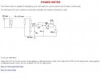 This Power meter is capable of dissipating up to 100 watts for a short period and 20 watts continuously
 -
 The Lakeshore Repeater Association (KR9RK) operates a **VHF** 2-meter repeater on 147.270 MHz, utilizing a +600 kHz offset and a 100 Hz PL tone, serving the Raymond, Wisconsin area. The organization provides access to monthly newsletters, with recent editions including March 2026, February 2026, and January 2026, detailing club activities and operational updates. A Google Docs link is provided for newsletters with functional embedded links, addressing issues with PDF versions. The association's Megacycle Group is actively constructing a **DX Contest** level HF network, designed for remote accessibility. This initiative aims to provide members with a competitive edge in global DX hunts by enabling worldwide access to the station's radios. Additionally, the Lakeshore Radio Association is commemorating its 50th anniversary with a special event station, K5O, inviting all members to participate in on-air operations.
 -
 100-watt UHF repeater (444.500+ PL100) and a 6-meter repeater (53.68- PL114.8) are owned and maintained by South County ARES to support emergency communications for Belmont, East Palo Alto, Foster City, Menlo Park/Atherton, Redwood City, San Carlos, San Mateo, and Woodside/Portola Valley. The organization emphasizes training, including weekly nets and practice sessions, to improve message passing accuracy and brevity, crucial skills for **emergency communication**. Resources like the San Mateo County Sheriff's Office Ham Radio Frequency Plan Recommendation and **Chirp-compatible CSV files** for Baofeng radios are provided. Participation in community events is encouraged to build skills and connections among members. The group operates without collecting dues, relying on donations and member contributions of time and expertise. Training pages are available for new hams and those seeking license upgrades, along with a "Tips for New Hams" section. The site also features a monthly calendar of events, including board meetings, general meetings, and hospital nets, alongside a newsletter, the "South County Communicator," and various operational documents like the Net Control Manual and SCARES Handbook.
 -
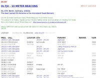
 Six meter band DJ9BV yagi antennas by YT1VP
 -
 The program consists of tabbed pages for various antenna and transmission line calculation. You can compute the values for an inverted L network that will allow you to match the 50 ohm output of the radio, or you can compute the necessary length in the units of choice for a 5/8 wave vertical for 10 meter band.
 -
 A Six-element Yagi Beam for 6 Meter by W1JR proiddes a power gain of 10.2 dB over a dipole it is built on a 24 foot long boom
 -
 The **Arlington Amateur Radio Club** (K5SLD) website details club activities, including a weekly Taco Tuesday net on their 147.140 MHz repeater with a 110.9 Hz PL tone. The club, organized in July 1955 by 22 hams, also hosts monthly dining events and promotes Community Emergency Response Team (CERT) training through the Arlington Fire Department. Membership renewal information for 2026 dues is prominently featured, with an online payment option and a donation button available on the "Pay Dues" page. Club communications extend to a dedicated Facebook page for members and the wider amateur radio community. The site lists upcoming contests and encourages participation in local events. The 2-meter repeater net is open to all, fostering local camaraderie and technical exchange among hams in the Arlington, Texas area, regardless of club affiliation.
 -
 Beacon list for 10 meters band maintained by DL7JV
 -
 Details the Big Thunder Amateur Radio Club (BTARC), a long-standing amateur radio organization based in Boone County, Illinois, established in 1962. It covers the club's mission to enhance the skills of local hams, promote radio knowledge, and foster social interaction among operators. The resource outlines BTARC's commitment to community service, including emergency communications support through RACES, and its active participation in events like Field Day, fox hunts, and public service communications for local races. Explains the club's history, including the establishment of its first repeater in the 1970s by members WD9JGH, Mike George, K9ORU, and Claude Horsman, WB9PMM, using a VHF Engineering kit and a Sinclair duplexer. It provides specifications for two club-maintained FM repeaters: a 2-meter repeater on 147.375 MHz (+600 KHz shift, 100.0 Hz PL tone) and a 70-cm repeater on 442.825 MHz (+5 MHz shift, 114.8 Hz PL tone). The club hosts a weekly 2-meter net on Sundays at 7:00 PM local time and holds monthly meetings on the second Thursday at the Spring Township Building in Belvidere, IL.
 -
 Amateur radio repeaters extend communication range for mobile and remote stations by retransmitting signals on a different frequency, often for emergency communications. The resource details various repeater bands, noting that 2 meters and 70 cm are primary for activity, with 10-meter repeaters offering potential national and overseas coverage. It specifies **18 channels** on 6 meters and **31 channels** on 2 meters, along with a new 70 cm offset of _7 MHz_ adopted in 2015. The content explains how repeaters can be linked via dedicated transmitters/receivers, landlines, or Internet VoIP systems like _IRLP_ and Echolink, enabling global connections. It also describes simplex gateways for multi-band operation and the use of CTCSS subaudible tones for access control and interference mitigation. The document highlights specialized repeaters for modes beyond voice, such as SSTV and ATV, particularly on 70cm and higher bands. Operational guidelines for efficient and courteous repeater use are referenced, along with links to Australian repeater listings and band plans.
 -
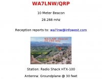
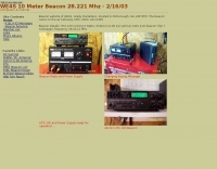 Beacon website of WE4S, Grady Donaldson, located in McDonough, GA. EM73TM.
 -
 A multi band antenna for HF band capable to operate from 10 to 80 meters band depending on wire lenght loaded with a small inductance neat the feed end.
 -
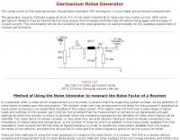 This generator requires 100volts supply at 5mA. A 0 -5 mA meter inserted at J1 measures the crystal current.
 -
 Constructing a basic multimeter involves integrating a 0-1mA meter movement with various shunts and multipliers, selected via a switch, to create a versatile instrument capable of measuring DC volts, current, and resistance. The design outlines two main units: a primary unit handling six DC current ranges up to 1 amp and eight DC voltage ranges up to 1000 volts, alongside an internal battery for an ohms range up to 200,000 ohms. This approach allows for a practical, hands-on understanding of meter operation. An add-on unit further extends the multimeter's capabilities, incorporating a meter rectifier and switched series resistors to provide four AC voltage ranges up to 100 volts. Additional shunt and series resistors, designated Ra and Rb, are included to expand the instrument's range to 10A and 5kV, demonstrating how modular design can enhance functionality. When this add-on is in use, the main instrument is set to measure 1mA FSD, connecting via specific lugs. Component selection emphasizes precision, with 1% tolerance high stability resistors for series elements and Eureka resistance wire for shunts. The design specifies values calculated for a meter with 60 ohms internal resistance, noting that these would require modification for different meter characteristics. Experimental adjustment of shunt values is recommended to ensure accurate readings against a calibrated reference meter, reinforcing practical calibration techniques.
 -
 Developing operational amateur radio equipment for the 134 GHz band presents significant technical challenges, particularly in frequency generation and stability. This resource details the construction of a 134 GHz system, outlining its architecture with separate transmit (Tx) and receive (Rx) modules, each employing a local oscillator (LO) and RF head units. The system utilizes a dual Flann 50 GHz lens-type horn antenna configuration for optimal signal coupling. The transmit path incorporates an LMX2541 synthesizer chip operating at approximately 2.8 GHz, referenced by a 10 MHz double-oven Morion OCXO for exceptional stability. This signal is multiplied through a series of stages (X4, then X2) to generate a 22.4 GHz signal, which subsequently drives a dual series diode multiplier to produce the final X6 signal for 134 GHz operation. The receive side features an anti-parallel diode mixer coupled to a 144 MHz transceiver via a preamplifier, ensuring effective downconversion. Operational mode is CW, achieved by keying a multiplier stage. The project includes images of the Tx and Rx head units and describes a successful 3.5 km test with G8ACE, demonstrating stable signal tones due to PLLs locked to OCXOs at both ends, confirming the system's robust performance.
 -
 The Boone Area Radio Klub (BARK) serves Boone County, Iowa, as its local amateur radio club, actively welcoming visitors to its meetings and weekly ARES nets. The club maintains a 2-meter repeater on 146.850/250 MHz with a 114.8 Hz tone and a 440 MHz repeater on 443.9+ MHz, both situated at the Boone County Hospital, with a simplex fallback on 146.550 MHz for the 2-meter net. Additionally, BARK supports the Iowa 160-meter ARES net at 1.972.5 MHz, which operates at 9:30 PM on Sundays, featuring a rotating schedule of net controls including KNØR, KBØMPL, NØISU, KEØQEU, and KBØLPI. BARK conducts bimonthly license testing sessions on the second Saturday of even-numbered months, with specific dates like October 19, 2024, at the Hamboree, requiring a $15 fee and prior FCC Registration Number (FRN) acquisition. The club's activities are well-documented through numerous photo galleries from past Field Days (1998, 1999, 2008, 2010, 2013, 2017, 2018, 2019), JOTA events (2013), and special event stations (2010 B&SVRR&M). Members like KBØMPL (Margot Conard) have contributed educational PowerPoint presentations on topics such as "Fun with Handie Talkies," "HF Propagation," and "Digital Mode - FLDIGI - OLIVIA 8/500 - JT65 HF - BAND PLANS." The club's officers, as of May 2018, include WØFS (Clay Conard) as President, NØISU (Mitch Carroll) as Vice-President, and KBØLPI (Eric Sloan) as Treasurer/Secretary, guiding the club's operations and community engagement.
 -
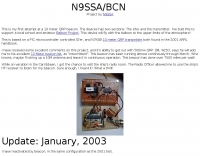
 The ZS1J/B beacon operates on 28.2025 MHz with 5 Watts output to a half-wave, end-fed vertical antenna, initially installed in 1977 as ZS5VHF near Durban. The 10-meter transmitter is a modified 23-channel CB radio, and the identification keyer uses a diode matrix unit with TTL ICs from the same era. After relocation to Plettenberg Bay in 1993, the beacon has been in continuous service, with additional QRP transmitters later installed for other bands. In 1994, a single-transistor, 80-meter, 0.5-watt QRP transmitter with a half-wave dipole was added on 3586 kHz, followed by a 160-meter, 0.5-watt unit on 1817 kHz. A 30-meter, 0.5-watt transmitter was installed in 1996, operating on 10.124 MHz. In 2002, a 40-meter QRRP beacon on 7029 kHz, with an output of 100 microwatts, achieved DX reports up to 1100 km from ZS6UT in Pretoria. Best DX reports for the 80m and 160m beacons came from 9J2BO.
 -
 Low-frequency (LF) radio time signals, operating primarily in the 40–80 kHz range, are broadcast by national physics laboratories for precise clock synchronization. Transmitters like **JJY** (40 kHz, 50 kW; 60 kHz, 50 kW), RTZ (50 kHz, 10 kW ERP), MSF (60 kHz, 15 kW ERP), WWVB (60 kHz, 50 kW ERP), RBU (66.66 kHz, 10 kW), and DCF77 (77.5 kHz, 50 kW) cover vast geographic areas, often several hundred to thousands of kilometers. LF signals offer distinct propagation advantages over higher-band transmissions such as GPS. Their long wavelengths (3–6 km) enable effective diffraction around obstacles like mountains and buildings. The ionosphere and ground act as a waveguide, eliminating the need for line-of-sight and allowing a single powerful station to cover extensive regions. Ground wave propagation minimizes ionospheric variability effects on transmission delay, and signals penetrate most building walls effectively. Robust and low-cost receivers, often priced at 20–30 USD/EUR, are widely used in radio clocks. These receivers typically comprise a tuned ferrite core antenna, a receiver IC (e.g., Atmel T4227, U4223B, MAS1016) for amplification and AM detection, and a microcontroller for decoding the time signal and phase-locking a local clock. Specific components for DCF77, MSF, and WWVB are readily available from vendors like HKW Elektronik and Ultralink.
 -
 The Tri-pole antenna, a clever modification of a standard dipole, allows for dual-band operation by integrating a third element. This design effectively shortens the overall dipole length by 10 to 20 percent, simplifying antenna rotation and offering a compact footprint. KK4OBI's article delves into the operational principles, using a 6 and 10-meter Tri-pole as a primary example, and provides comprehensive instructions for constructing any Tri-pole antenna within the 6 to 15-meter range. Key to the Tri-pole's performance is its off-center feed, necessitating a common mode choke at the feed point for optimal tuning and reduced noise. The author outlines a methodical approach to determining element dimensions, starting with a vertical element frequency calculated as 0.47 times the sum of the desired upper and lower band frequencies. This calculation, along with K-values derived from trend lines, guides the initial lengths for the horizontal arms, demonstrating how a 10m-6m Tri-pole can achieve a total horizontal length 78% shorter than a conventional 10-meter dipole. Tuning and balancing are critical, with the article detailing adjustments to arm lengths and the vertical element to achieve balanced SWR values, as validated through 4NEC2 simulations. Radiation patterns are analyzed at various elevations, showing gains around 5.7 dBi and favorable take-off angles for DX contacts. Construction details specify aluminum tubing dimensions, U-bolts, and an SO-239 connector, emphasizing the importance of a ferrite-based choke for wideband operation.
 -
-
 Basic magnetic loop antenna examples and loop aerials theory explained. This article inclued some interesting tricks on building magnetic loop antennas and an usefull excell sheet to help compute magneti loop antennas calculating power efficiency from 10 to 40 meters band
 -
 Basically, this antenna is a 23-foot wire fed through a 4:1 un-un transformer. This antenna can be easily used in portable operation, for operating all bands from 40-10 meters.
 -
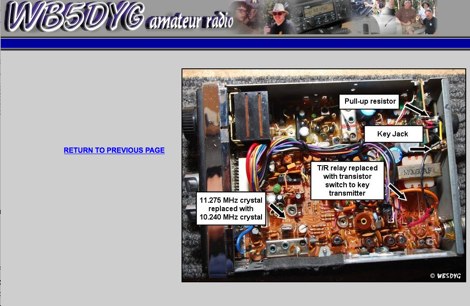 AC7GZ/B is a converted Sharp CB-2460 Citizens Band transceiver operatin on 28.2118 MHz.
 -
 DF0WD/DL4YHF's Longwave Overview details amateur radio operations on the 135.7 to 137.8 kHz segment in Germany. The author outlines the "inofficial" European band plan, specifying segments for QRSS, TX tests, beacons, conventional CW, and data modes. Early LF activities at DF0WD began with a 20-watt CW transmitter, later upgraded to a homemade linear transverter capable of 100 watts, driven by an Icom IC706 on 10.137 MHz. The station's antenna system includes a 200-meter wire, approximately 10 meters above ground, supported by football field light-masts. Despite its length, the antenna's efficiency is noted as very low due to the immense wavelength of about 2.2 km. The author's experience highlights the significant challenge of achieving effective radiated power (EIRP) on LF, estimating DF0WD's EIRP at around 80 milliwatts based on field strength measurements from PA0SE. DF0WD/DL4YHF has successfully worked numerous countries on 136 kHz CW, including DL, F, G, GI, GM, GU, GW, HB9, HB0, LX, OE, OH, OK, OM, ON, OZ, PA, and SM. The author also mentions ongoing efforts to log contacts with CT, EI, LA/LG, and to complete a two-way QSO with Italy, demonstrating persistent activity on this challenging band.