Search results
Query: 40m 80m
Links: 78 | Categories: 1
Categories
-
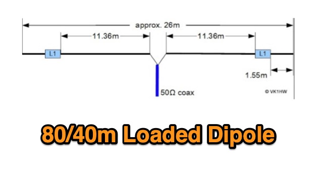 A dual band dipole antenna for 40 and 80 meters band. Total lenght of 26 meters, foreseen two coils at aprox 11 meters distance from center feed.
 -
 The CQ World Wide DX Contest records page details the highest scores achieved in the CQ WW DX Contest across various categories and years. It systematically lists records for both SSB and CW modes, segmenting results by entry class such as Multi-Multi, Multi-Two, Multi-Single High, Multi-Single Low, Single Operator High Power, Single Operator Low Power, Single Operator QRP, Single Operator Assisted High, Single Operator Assisted Low, and Single Operator Assisted QRP. Each record entry specifies the callsign, the operator's callsign in parentheses if different, the year of operation, and the total score achieved. The data is further broken down by individual amateur radio bands, including 160m, 80m, 40m, 20m, 15m, and 10m, allowing for granular analysis of performance within specific frequency segments. The page also includes records for the "ALL" band category, representing cumulative scores across all operational bands. The presented records span from 1948 to 2025, providing a historical perspective on contest performance. This resource also references other CQ contests like CQ WPX, CQ WW RTTY, CQ WPX RTTY, CQ 160, CQ VHF, and WW DIGI, indicating a broader context of contest record keeping. It explicitly states that late logs are not included in the records, ensuring data integrity. The page is maintained by the World Wide Radio Operators Foundation, Inc.
 -
 The CQ World Wide DX Contest records document top scores, with the Multi-Multi SSB category showing CN8WW achieving **78,170,508 points** in 2000. These records span from 1948 to 2025, categorizing results by region, operating class (e.g., Single Operator High Power, Low Power, QRP, Assisted), and specific bands like 10M, 15M, 20M, 40M, 80M, and 160M. For instance, EF8R (E77DX) holds the All-Band High Power SSB record with **25,747,775 points** in 2025. Each entry includes the callsign (with operator callsign in parentheses for guest ops), year of operation, and total score. The _CQ WW DX Contest_ also features records for the RTTY and VHF contests, alongside the main SSB and CW categories. QRP records demonstrate significant achievements, such as P40W (W2GD) with 5,097,780 points in the All-Band SSB QRP category in 2000. Multi-Two and Multi-Single categories are also detailed, providing a comprehensive overview of competitive performance.
 -
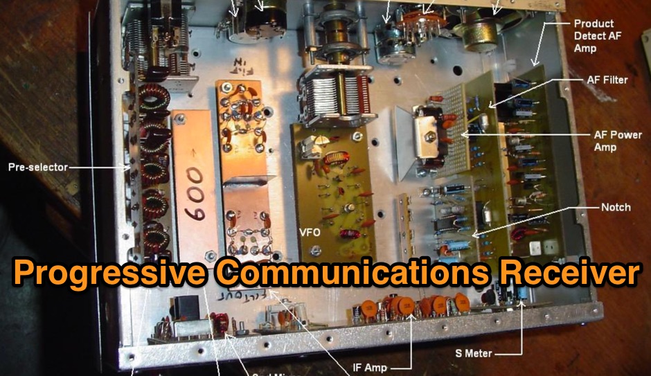 The purpose of this webpage is to document an attempt at this project starting with the 80m core receiver first and also having the parts on hand for then adding the first dual conversion band (40m)
 -
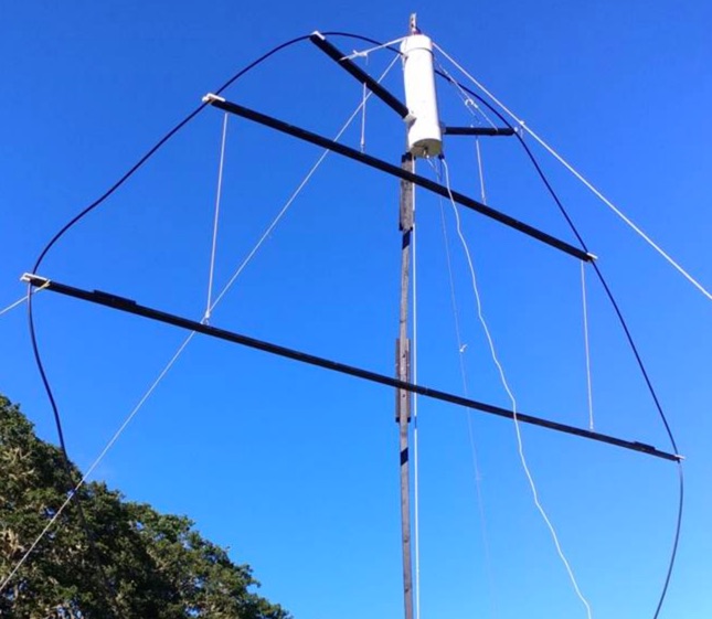 A portable (15.5 foot diameter) NVIS loop for 3.5 to 7.3 MHz. Performs well at high and low takeoff angles, and has smaller footprint than most NVIS antennas.
 -
 Designing and constructing a two-element receiving loop antenna array for HF operation involves specific considerations for achieving high directivity and noise reduction. This resource details a homebrew system comprising two 30-inch diamond-shaped loops, spaced 20 feet apart, which are fed through mast-mounted preamplifiers and passive signal combiners. The operational principle relies on adjusting phase delays between elements via precise _Belden 8241_ coaxial cable lengths, optimized for specific bands from 160m to 20m. Performance data, derived from _EZ-NEC_ modeling, illustrates consistent 90° azimuth-plane beamwidth and low take-off angles across the target bands, with _Receiving Directivity Factor_ (RDF) values comparable to a 300-foot Beverage antenna. The article presents detailed elevation and azimuth plots for 20m, 30m, 40m, 80m, and 160m, demonstrating the array's ability to provide strong response at low DX angles while also supporting _NVIS_ signals. Key components like the _DX Engineering RPA-1_ preamplifier and _DXE RSC-2_ signal combiner are discussed, alongside the importance of impedance matching to preserve antenna patterns. The construction emphasizes self-contained elements that do not require ground radials, offering a compact solution suitable for suburban environments and stealth installations, with a focus on optimizing receive performance independently from transmit antennas.
 -
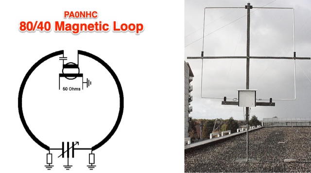 No matching adjustments needed. Directly perfect match to 50 Ohms using a remotely switched wideband transformer
 -
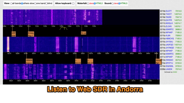 Listen to online WebSDR located in Andorra Europe. Four receivers on 60m, 20m, 40m, and 80m, connected to a dipole antenna direction East/West
 -
 DL7JV shares his practical experience building and testing capacitive antennas, initially skeptical of their performance compared to magnetic loops and mono-band dipoles. His interest was piqued after hearing a Spanish station running 100 Watts on 80 meters with a 1-meter Micro Vert, making DX contacts into PY and UA0, despite the antenna being only 4 meters high in a garden. This prompted DL7JV to investigate further, consulting resources from DL7PE and DL7AHW, the latter providing DOS programs like "Mitspule.exe" and "Spulenprg.zip" for calculating antenna dimensions and coil conversions. The article outlines the construction of two prototype antennas: one for 7.050 MHz using a 75mm PVC pipe and another for 3.550 MHz with a 110mm PVC pipe. Both designs feature aluminum foil condensers and coils wound from 1mm² H07V-K wire. DL7JV provides specific measurements for the condenser capacitance, surface area, diameter, height, coil inductance, turns, and wire length for both 40m and 80m versions, along with RG58 feedline lengths. Initial reception tests for the 7 MHz antenna, placed indoors, yielded impressive S9+5 signals from a German station compared to an S8 from a 42-meter roof-mounted loop, even hearing a Japanese station. Transmission attempts on April 4, 2004, despite moderate solar storm conditions, resulted in successful QSOs on 7 MHz with EA5OT (579/559) and on 3.5 MHz with YT1NT (579/559) and G4KKI (579/559) using 100 Watts. DL7JV notes the antenna's sensitivity to coordination and feedline layout, suggesting a modification from DL7AXO involving a 500pF fixed capacitor and coil tap for improved SWR stability. He concludes that while the capacitive antenna is space-saving and performs well for reception and 100W transmission indoors, its transmit performance doesn't yet match larger antennas, with further outdoor field tests planned. DL7JV also intends to build a 1.8 MHz version.
 -
 This article documents the author's journey in building, modifying, and testing a DIY short vertical antenna for 40, 30, and 20 meters, with potential 80m capability. Initially inspired by Parks On The Air (POTA), the author explores pedestrian mobile operation and details various experiments to enhance antenna performance. The piece highlights challenges, SWR tuning, portability, and practical results, emphasizing a balance between efficiency and size. Ultimately, it showcases the adaptability of DIY antennas for portable ham radio applications.
 -
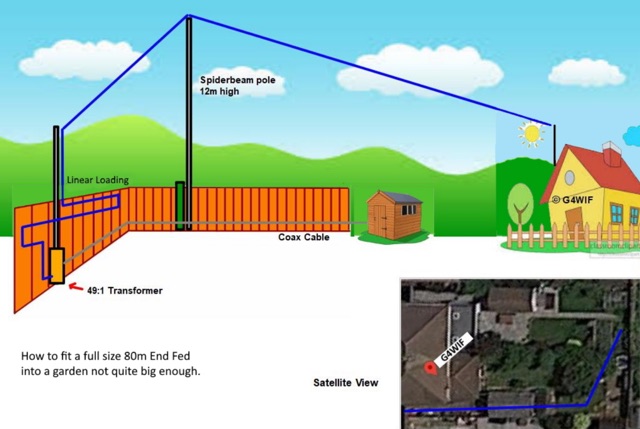 The author reflects on expanding their antenna for 80m coverage during lockdown. They extend the End Fed Half Wave (EFHW) using a Spiderbeam pole and "cheating" by dog-legging across their garden. Despite challenges, they achieve coverage for multiple bands with minimal cost. Practical Wireless features EFHW antennas, including a pre-made 20m EFHW extended for 40m.
 -
 WB8LZR details the construction and initial field results of a multi-band vertical wire antenna, designed to complement his existing horizontal loop for improved DX on 80 meters. The antenna utilizes a 67-foot vertical wire, configured as a quarter-wave radiator on 80m, and employs a 1:1 current balun for RF isolation on 80m, 30m, and 17m. For bands like 40m, 20m, and 10m, where the wire acts as a half-wave or full-wave radiator, an additional impedance transforming _unun_ is integrated to manage the significantly higher feedpoint impedance and voltage. The author notes the vertical's performance as a receiving antenna, observing reduced noise compared to his main horizontal loop, particularly on 80m, and even hearing some long-path signals the loop missed. Initial QRP contacts, including a **1-watt** QSO with a _VP2 station_ on 30m, demonstrate its transmit capability. While the radial system is currently rudimentary, the project outlines practical considerations for multi-band vertical deployment and impedance matching.
 -
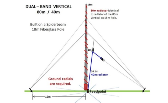 A dual band 40-80 vertical antenna on an 18m Spiderbeam Fiberglass Spiderpole, with monoband performance
 -
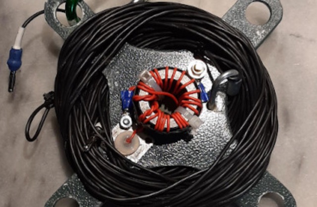 How to Design and Build a Field Expedient End-Fed Half-Wave Antenna for 20m, 40m and 80m. This Shorty 80m EFHW comprises a 49:1 autotransformer (to match the very high impedance at the end of a half-wave wire), a half-wavelength wire for 40m (also a quarter-wavelength for 80m), a loading coil and a short tail wire. The coil and the short tail wire (about 6 feet) make up the other quarter wave on 80m.
 -
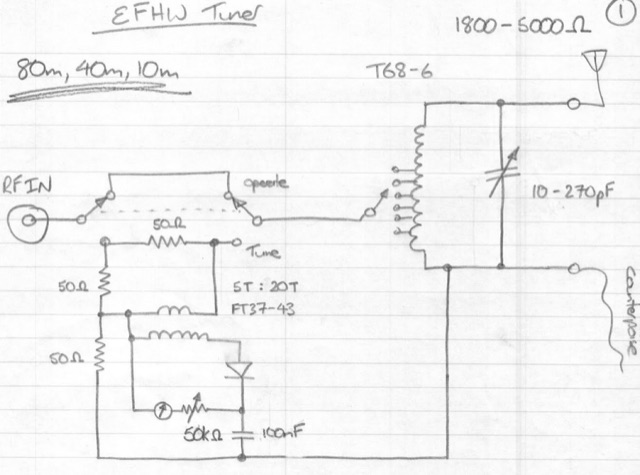 Schemaric diagram for a 80m, 40m, 30m, 20m EFHW Antenna Antenna Tuner. The tuner has been designed for an antenna length of 41m and the counterpoise 7.5m.
 -
 Dipole for 40m band. It is a simple linear loaded dipole feeded with 450-Ohm openwire feedline. Designed it for resonance at 7.050 MHz, can be tuned on 30m and 80m bands with an external antenna tuner. Build with simple electrical copper wire (2.5 mmq/13 awg) and two fishing poles with size of about 7 m/23 ft.
 -
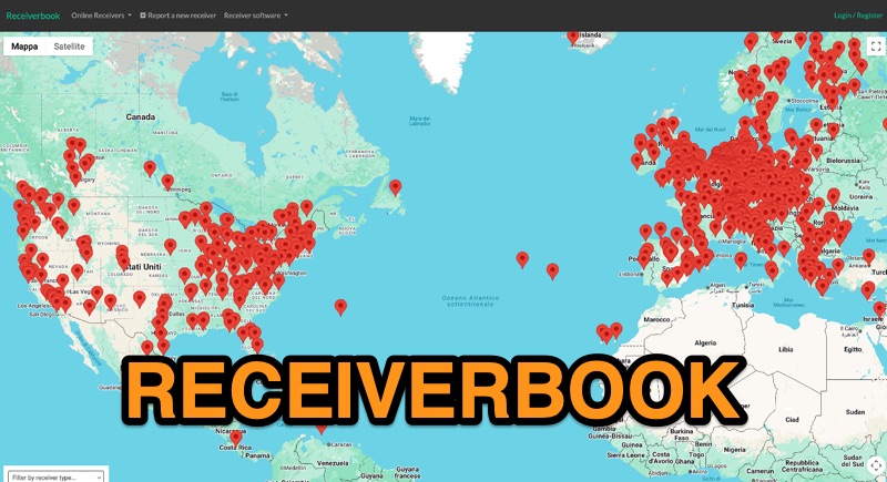 Monitoring radio communications through web-accessible Software Defined Radios (SDRs) has become a popular facet of the hobby, and Receiverbook serves as a centralized directory for locating these remote assets. The platform aggregates listings for both **OpenWebRX+** and **KiwiSDR** installations, providing a gateway to a diverse array of frequencies and operating modes. My own experience with similar directories highlights their utility for casual listening, DXing, and even troubleshooting local RFI by comparing signals across different geographic locations. The directory details specific receiver locations, from Bedford, England, to Marahau, New Zealand, and Berlin, Germany. Each entry often specifies the supported frequency ranges, which can span LF, MF, HF, VHF, and UHF bands, including dedicated segments like 80m, 40m, 2m, and 70cm. Many listings explicitly note support for HAM radio, broadcast services, and public two-way radio, making it a versatile tool for various listening interests. Beyond general frequency coverage, some entries provide granular details about the underlying hardware, such as the **SDRPlay RSP1A** or RTL-SDR Blog V3, and even the antenna types employed, like the Sirio Gain-Master. This level of detail is invaluable for serious SWLs and hams looking to understand the capabilities and limitations of a particular remote receiver before tuning in.
 -
 Demonstrates the ZS6BKW multiband HF antenna, a design by ZS6BKW (G0GSF) that improves upon the G5RV by offering direct resonance on multiple bands without an antenna tuner. The resource details the antenna's 90-foot length and 40-foot 450-ohm twin lead downlead, emphasizing its suitability for hams with limited space or budget. It covers both horizontal and inverted-V configurations, noting the inverted-V's single-support advantage and the importance of maintaining an apex angle of at least 90 degrees to prevent signal cancellation. The author, G3UKV, shares his preference for 450-ohm twin lead over 300-ohm due to its superior strength and lower losses, especially in wet conditions, drawing from his extensive field experience. The document presents recorded SWR and impedance (R) measurements taken with an MFJ Antenna Analyzer, confirming excellent performance on 40m, 20m, 17m, 12m, 10m, and 6m, often with SWRs below 1.3:1. It also discusses the antenna's tunability on 80m with an ATU and suggests a method for 160m operation. G3UKV recounts receiving "excellent reports" on 7 MHz and 14 MHz, validating the antenna's effectiveness. Practical advice includes keeping antenna ends clear of ground by at least a yard to avoid detuning and the recommendation of a 1:1 current balun where the 450-ohm feeder connects to 50-ohm coax.
 -
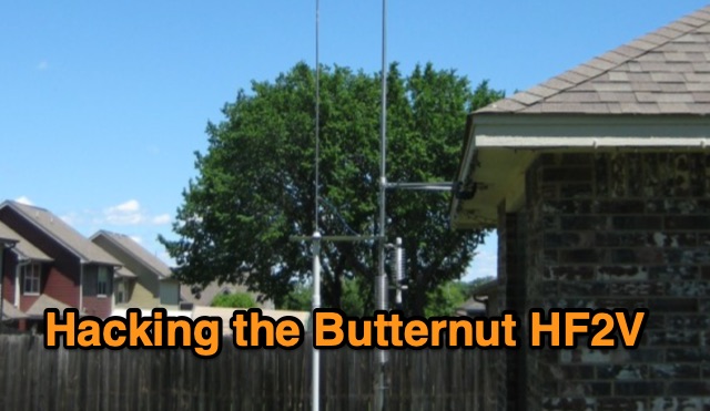 The Butternut HF2V, originally a two-band vertical antenna for 80m and 40m, was enhanced by the user to include 30m and 20m bands for better digimode DX work during the solar minimum. The additions used components adapted from the HF6V and innovative methods for the 20m addition, either through a parallel vertical element or a lower-mounted independent element, minimizing band interaction. This modified four-band antenna now supports high power across popular HF bands using a single feedpoint.
 -
 The tri-band trapped delta loop antenna design operates on 80 meters (3.5–4 MHz), 40 meters (7–7.3 MHz), and 30 meters (10.1–10.15 MHz) using a single triangular wire loop. This configuration eliminates the need for an external antenna tuner or band-switching relays. The antenna's physical perimeter, approximately 270 feet, establishes 80M as the fundamental band, with specific trap placements enabling resonance on 40M and 30M. Trap design and placement are critical, with 30M traps positioned inboard of 40M traps within the horizontal element. Each slant leg measures approximately 80 feet. The resource references foundational information from the _ARRL Antenna Handbook_ and _ON4UN’s Low Band DXing_ regarding full-wave loop behavior and feedpoint impedances. The project aims to provide multi-band HF operation from a single, fixed antenna structure.
 -
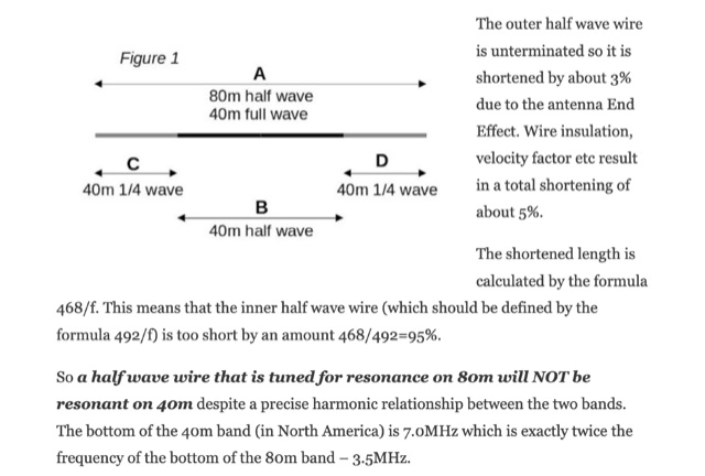 A half wave wire that is tuned for resonance on 80m will NOT be resonant on 40m despite a precise harmonic relationship between the two bands. The End Effect is caused by a capacitive coupling between an unterminated wire end and the ground.
 -
 From March 2 to March 11, 2018, a Norwegian team operated as Z2LA from Zimbabwe, focusing on 160m through 10m bands using SSB and CW modes. The operation, described as "holiday style," aimed to provide contacts for DXers worldwide seeking a rare DXCC entity. Key equipment included a SUNSDR PRO II, an Elecraft KX3, and an Icom 706 MK2G as a spare radio, supported by two Juma 1000 amplifiers for robust signal output across the bands. Antenna systems were tailored for multi-band operation, featuring an Inv L for 160m and 80m, sloping dipoles for 30m/40m, and a _Hexbeam_ from SP7IDX Technology covering 20m to 10m. For improved reception, the team deployed a SAL 30, two reversible BEV antennas from remoteqth.com, and a BOG from K1FZ, enhancing their ability to hear weak signals. QSL information directs operators to Clublog for log search and M0OXO Charles for OQRS, explicitly requesting no bureau cards. The team comprised LA7THA Rune, LA7WCA Arne, and LA9VPA Thor, successfully making numerous contacts and contributing to the DX community's pursuit of _Zimbabwe_ as a DXCC entity.
 -
 DF6QV's 4-Square antenna analysis begins with a two-element array simulation, demonstrating azimuth and elevation plots for various phase differences, including a 75-135 degree range. The document then delves into the core components of a 4-Square system, such as radiators, couplers, phasing lines, and ground systems, referencing W1HKK's 1965 QST article on an 80m phased array. It explores the influence of ground conditions and element spacing on antenna performance, presenting EZNEC analysis for an 80m 4-Square with an elevated radial, showing how gain and beamwidth vary with spacing. Various 90-degree couplers, including the 3 dB hybrid coupler and the Reed Fisher coupler, are analyzed using LTSpice, detailing power splitting, phasing, and bandwidth characteristics. The resource quantifies power, voltage, current, and losses within a 4-Square system, addressing relays, capacitors, inductors, radiator radial systems, and cable losses. System impedance, bandwidth, SWR, isolation, and mutual coupling are discussed with practical construction aspects covering common mode chokes, phasing boxes, and remote control systems. Field test observations for 40m 4-Square antennas are included, with specific examples from DXpedition operations like 5A7A and VP6DX, providing real-world context to the theoretical and simulated results.
 -
 The RI1FJL DXpedition to Franz Josef Land, planned for August 2026, will deploy at least five high-power stations operating 24/7 across all **HF bands** for 15 days. The team of six operators, including R7AL and UA3QLC, will depart Murmansk on August 7, 2026, aboard a 20-meter sailing yacht, aiming for Heiss Island (IOTA: EU-019, QTH Loc.: LR80tn, CQ zone: 40, ITU zone: 75). Operating modes will encompass CW, SSB, and FT8, with specific FT8 frequencies like 1836.0 kHz and 14095.0 kHz designated for MSHV software. Equipment includes EE SUNSDR2 DX and Elecraft K3 transceivers, paired with Expert 1.3K-FA power amplifiers, and a variety of antennas such as Spiderbeams and phased GPs for 40m, 80m, and 160m. The expedition emphasizes working distant regions and low-power stations, acknowledging the challenging Arctic conditions with average temperatures around 1-3°C below zero. The logistical planning includes securing accommodation at the Geophysical Polar Observatory on Heiss Island and navigating potential ice conditions for zodiac landings. QSL information specifies ClubLog uploads at least daily, with OQRS available for direct and bureau QSLs. Donors contributing $10 or more receive fast LoTW confirmation and direct QSL cards, while Platinum Donors of $100+ will have their callsigns featured on the QSL card. A special plaque is offered for two QSOs with RI1FJL on different bands or modes.
 -
 Details the construction and performance of a phase-controlled receiving array, specifically a **MicroSWA** variant, optimized for QRP low band fox hunting on 40M and 80M. The resource documents the author's iterative design process, addressing significant regional noise challenges encountered during 0100-0230 UTC fox hunt periods. Initial experiments involved a director wire on a 40M vertical, yielding limited improvement, prompting a shift towards advanced null-steering techniques. The project leverages concepts from Victor Misek’s "The Beverage Antenna Handbook" and Dallas Lankford’s extensive work on phased receiving antennas for urban lots. A key modification involved integrating a new passive phase control box and a push-pull **Norton common base preamp** using 2N5109 transistors, designed for high third-order intercept performance to maintain weak signal integrity amidst strong adjacent signals. The system incorporates Faraday-shielded transformers with RG174 primaries on -75 ferrite cores, housed in ABS plastic pipe. Performance tests confirmed the MicroSWA's ability to produce deep, steerable nulls, achieving approximately 30 dB noise reduction on 160M, 80M, and 40M. This enabled detection of QRP signals undetectable on conventional transmit antennas. The final unit includes front panel controls, a 10-11 dB preamp, and a robust power conditioner, demonstrating effective noise mitigation for challenging low band QRP operations.
 -
 Presents detailed expedition charts and statistics for the **XX9W** DXpedition, covering operating time, total QSOs, unique calls, and duplicate QSOs. The resource provides comprehensive band and mode breakdowns, including FT8, SSB, CW, and FM, across 80m, 40m, 30m, 20m, 17m, 15m, 12m, 10m, 6m, 2m, and 70cm. Users can access DXCC statistics by band and mode, daily QSO totals, and multiband QSO statistics. Continent-by-mode and continent-by-band breakdowns are also available, detailing activity from Africa, Asia, Europe, North America, Oceania, and South America. The platform also tracks the expedition's impact on user totals, showing new band, new mode, new band + new mode, new slot, and new DXCC contacts.
 -
 The XW4DX DXpedition website documents the amateur radio operation from Laos, a country ranked #98 on Clublog's Most Wanted list. This resource provides insights into the planning and execution of a significant DXpedition, including antenna choices like _Hexbeams_ at 14m, a 4-square for 40m, and a top-loaded vertical for 160m. The team, comprising operators such as _F4BKV Vincent_ and _F2DX Patrick_, focused on challenging paths, particularly towards the North American East Coast, where Laos is #41 most wanted. Operational constraints included prohibitions on 6m, 30m, 60m, and 80m bands within Laos, necessitating a focus on other HF frequencies, especially 160m and 40m. The expedition utilized up to five stations simultaneously, with equipment transportation being a major logistical challenge, partially mitigated by direct shipments from _Spiderbeam_ and donor support. The expedition ran from November 16th to 27th, 2023, with the complete XW4DX log uploaded to LoTW by December 23rd, 2023. This site serves as a historical record of their efforts to put Laos on the air for DXers worldwide.
 -
 Demonstrates a LoRa APRS Tracker project featuring a comprehensive menu system for message management, weather requests, and monitoring nearby trackers. The device supports adjustable display eco mode and screen brightness, optimizing power consumption by dynamically changing processor speed from 240MHz to 80MHz. GPS beacons are encoded for efficient RF transmission, and an OLED screen displays altitude, speed, course, _BME280_ weather data, or new message counts, along with recently heard stations. Bluetooth connectivity enables operation as a TNC with Android (APRSdroid) or iPhone (APRS.fi app), providing LED and sound notifications for transmissions and received messages. The integrated BME280 module facilitates weather data display and transmission, with Winlink mail support via _APRSLink_. The tracker can switch between **three major LoRa APRS frequencies** worldwide, offering versatile global operation.