Search results
Query: RF choke
Links: 61 | Categories: 1
Categories
-
 A C-Pole Antenna for QRPxpeditions describes a DIY C-Pole antenna designed for QRP (low-power) expeditions, inspired by KF2YN’s ground-independent vertical model. After adjustments, it achieved a 1:1 SWR at 14.060 MHz, rising to 2.5:1 at 14.35 MHz. A choke balun, comprising 15 turns of RG8X around a 4†can, was essential for optimal performance. Compact and self-supporting, the antenna enables reliable communication with minimal setup. Contacts included stations across the U.S., and even a 4,600-mile connection to Spain using only 5 watts.
 -
 With increased ES propagation, this lightweight 5-element LFA antenna offers enhanced performance over the Bigwheel antenna's 5dBi gain, delivering approximately 11dBi and forward gain. Designed from G0KSC’s specifications, the 1.8m antenna was adapted for reduced weight using 6mm and 4mm rods instead of heavier tubes. 3D-printed PETG clamps ensure durability and precision, while the first tests showed excellent SWR and element coupling. Though built with a temporary Choke BalUn, the results were promising, with a Pawsey Stub BalUn planned next for further optimization.
 -
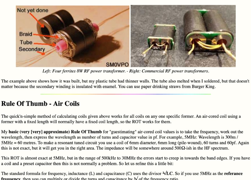 Demonstrates practical **rules of thumb** for selecting and utilizing ferrites and coils in amateur radio projects, particularly for RF applications up to 30 MHz. It addresses common challenges like determining appropriate ferrite grades and estimating L/C values without precise specifications. The resource details the author's experience with readily available grey ferrites, noting their suitability for HF work, and provides guidance on constructing **baluns** and RF chokes, balancing inductance for lower frequencies against inter-wire capacitance for higher frequencies. It also outlines a method for estimating power handling based on ferrite weight, suggesting a 1-gram ferrite can manage over 2 Watts, and offers a technique for evaluating unknown ferrites by winding 10 turns and measuring resonance with a 1 nF capacitor. This approach emphasizes a hands-on, iterative method for balun winding and adjustment, allowing operators to quickly approximate component values. The article compares the characteristics of ferrite-cored coils with air-cored coils, highlighting the reduced pickup and radiation of ferrite designs. It refines the air-coil estimation method for frequencies between 2.5 MHz and 10 MHz and provides a scaling factor for frequencies outside this range, aiming to get operators into the correct general area for their designs. The author's standardized ferrite choice (RND Components 165-00182) is presented as a practical example for reproducible projects.
 -
 Details the construction of a Copper Cactus Dual-Band Super J-Pole Antenna, providing specific measurements for 1/2-inch copper tubing sections, including a 57-1/2-inch long section and a 19-inch short section, along with a 42-inch piece of 3/16-inch or 1/4-inch soft copper tubing for the matching stub. It covers soldering techniques for copper fittings, drilling an SO-239 panel mount coaxial fitting, and securing feed point connections with stainless steel adjustable band clamps. The resource specifies materials such as Schedule M 1/2-inch copper tubing, various copper fittings, a hardwood dowel or Fiberglas rod for insulation, and #14 stranded copper wire for the feed point. The guide simplifies the J-pole feed point by using an SO-239 fitting with an elongated mounting hole and band clamps, noting an optimal feed point distance of approximately 3 inches above the crossbar for proper impedance matching. It recommends a 4-turn coax choke, 5 inches in diameter, placed within 3 to 4 inches of the feed point for 2-meter operation to mitigate RF on the feedline. The project emphasizes weather sealing with silicon or butyl rubber compound and clear lacquer for durability and appearance.
 -
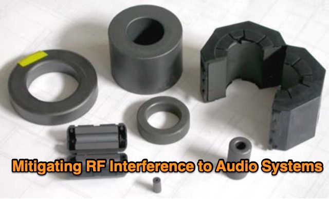 In this study, the author builds upon Muncy's research, demonstrating that radio-frequency current on cable shields affects audio systems through the "pin 1 problem" and shield-current-induced noise (SCIN). An enhanced equivalent circuit for ferrite chokes is proposed, addressing dimensional resonance and inductor self-resonance. Field tests confirm that chokes reduce interference across 500 kHz to 1,000 MHz. Guidelines for diagnosing and mitigating EMI from various sources are provided for product development and field installations.
 -
 DF6QV's 4-Square antenna analysis begins with a two-element array simulation, demonstrating azimuth and elevation plots for various phase differences, including a 75-135 degree range. The document then delves into the core components of a 4-Square system, such as radiators, couplers, phasing lines, and ground systems, referencing W1HKK's 1965 QST article on an 80m phased array. It explores the influence of ground conditions and element spacing on antenna performance, presenting EZNEC analysis for an 80m 4-Square with an elevated radial, showing how gain and beamwidth vary with spacing. Various 90-degree couplers, including the 3 dB hybrid coupler and the Reed Fisher coupler, are analyzed using LTSpice, detailing power splitting, phasing, and bandwidth characteristics. The resource quantifies power, voltage, current, and losses within a 4-Square system, addressing relays, capacitors, inductors, radiator radial systems, and cable losses. System impedance, bandwidth, SWR, isolation, and mutual coupling are discussed with practical construction aspects covering common mode chokes, phasing boxes, and remote control systems. Field test observations for 40m 4-Square antennas are included, with specific examples from DXpedition operations like 5A7A and VP6DX, providing real-world context to the theoretical and simulated results.
 -
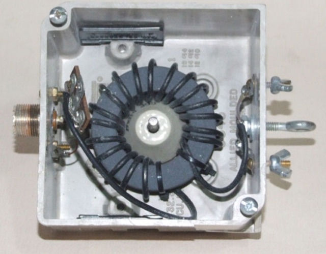 For phased C-Poles, matching choke baluns are essential to maintain intended phasing, beam pattern, and gain. The author uses a low-loss, ferrite-core balun design with 19 turns of RG-174/U coax for optimal performance.
 -
 Designing a collapsible 6-meter beam antenna involves careful consideration of element geometry and feedline matching, as demonstrated by VE3SMA's project. The construction draws inspiration from foldable dipole concepts and established wire beam designs like the Penn. State 40m beam and the DJ4SA Spiderbeam. Utilizing **4NEC2 modeling**, the author optimized element lengths for gain and bandwidth, observing the impact of end loops on resonant frequency and the need for compensation. Feeding the approximately 25-ohm balanced antenna with 50-ohm unbalanced cable required a specialized network. This setup incorporates a choke **balun** and a matching section built from two series quarter-wave transformers using readily available 75-ohm cable. On-the-air results validate the design, including a successful 1st double hop Es QSO with 10 Watts and satisfactory performance in the CW WW VHF Contest from FN05, where 41 grids were worked with 100 Watts, showing improved performance over a simple dipole.
 -
 Constructing a 4:1 Guanella current balun involves cross-connecting two 1:1 current baluns. At the low-impedance end, transmission lines from each balun are connected in parallel, while at the high-impedance end, they are connected in series. This configuration allows the device to achieve a 1:4 impedance ratio, effectively transforming a 200-ohm load to 50 ohms. The balun described utilizes **FT240-43 toroids** wound with 2.5mm2 twisted pair cable for 8 turns, intended for use with a 20m **Deltaloop antenna**. Measurements performed with a 200-ohm resistor demonstrate satisfactory VSWR and impedance characteristics across the HF bands. The article compares the performance of 2.5mm2 cable versus 1mm enameled wire, recommending the former for superior efficiency. Emphasis is placed on maintaining short core-terminal connections to optimize performance. Additional considerations include the option of integrating a separate Common Mode Choke (CMC) for enhanced common mode current suppression, especially if the balun's inherent suppression is not prioritized.
 -
 Constructing a **J-Pole antenna** from 450 Ohm ladder line for 2-meter (144 MHz) and 70-centimeter (440 MHz) operation involves specific calculations and assembly steps. The design, based on an earlier KD6GLF concept using 300 Ohm twinlead, features a ¾ wavelength radiator and a ¼ wavelength matching stub, functioning as an end-fed half-wave antenna without requiring ground radials. It offers a gain of 2.4 dB over isotropic. The resource provides the formulas for determining the lengths of the ¾ wave radiator and ¼ wave stub, incorporating a velocity factor of 91% for 450 Ohm ladder line. For 146 MHz, the radiator measures 55 3/16 inches and the stub 18 3/8 inches. Construction details include cutting a 57¾-inch piece of ladder line, stripping 4 inches from one end, and attaching a 24-inch section of RG58 or RG8X coax with a 3-5 turn RF choke. SWR adjustment is achieved by sliding a shorting bar or by incrementally trimming the elements at a 1:3 ratio (stub to radiator). The goal is a 1:1.1 SWR at 146 MHz, which typically yields 1:1.2 at 446 MHz. The article also discusses power handling, noting that while 10-15 watts is fine, 50 watts may increase SWR to 1:2.1, and advises keeping the antenna away from other objects to prevent coupling and SWR degradation.
 -
 Understanding how radio frequency interference (RFI) is coupled into equipment and subsequently detected is crucial for amateur radio operators. This guide delves into the fundamental mechanisms of RFI, particularly focusing on detection at semiconductor junctions and the unintended antenna action of system wiring. It explains that most RFI detection follows a square law, meaning a 6 dB reduction in RF signal can result in a 12 dB drop in detected audio, offering a practical approach to mitigation. The resource also clarifies the concept of common mode versus differential mode signals, detailing how cable imperfections can convert common mode antenna current into differential signals. It addresses the critical "Pin 1 Problem" in audio interfacing, a common design flaw where cable shields connect to the circuit board instead of the shielding enclosure, leading to significant RFI issues. Practical solutions, such as proper shielding, using twisted-pair cables, and strategic bonding of equipment, are discussed to effectively reduce or eliminate RFI. The guide emphasizes the importance of proper filtering and the often-misunderstood concept of "ground" in electrical systems, distinguishing between earth ground, equipment ground, and circuit common. It provides insights into minimizing loop area in wiring to reduce inductively coupled noise and antenna action, drawing on the author's extensive engineering background and ham radio experience.