Search results
Query: RF choke
Links: 61 | Categories: 1
Categories
-
 A 1/4 wavelength resonator design for dual-band VHF/UHF operation is presented, focusing on a robust mobile antenna construction. The design prioritizes stability against environmental influences over raw gain, making it suitable for general use rather than marginal signal areas. It details the antenna's two sections: a UHF-resonant lower conductor and an upper coil functioning as an RF choke for UHF and an inductance enhancer for VHF, forming a resonant circuit. Detailed mechanical structure and material considerations are provided, including the use of a PL-259 plug base, 2mm copper rod, and PVC faucet tube for the coil form. The guide outlines a precise construction procedure, from soldering the copper rod to the PL-259 to winding the 22 SWG laminated wire for the VHF section. Tuning involves careful cutting of the UHF section and adjusting the coil length and pitch for VHF, using a reflectometer and temporary ground planes. Furthermore, the resource describes converting the mobile antenna for base station application by constructing a dual-band ground plane system. This involves using electrical conduit, EMT connectors, SO-239 sockets, and a 4-inch round-pan with threaded stainless steel rods as ground elements. Practical test results indicate optimal lengths of **70mm** for UHF and **350mm** for VHF ground elements, with a recommendation to cut rods with _30mm_ extra length for fine-tuning.
 -
 A 9 dB gain 70cm collinear antenna construction is detailed, utilizing eight half-wavelength sections of _RG58/U_ coaxial cable. The design incorporates specific calculations for velocity factor (0.66 for RG58/U) to determine precise element lengths, such as 223mm for a half-wavelength at 444 MHz. A quarter-wave radiating element of #16 solid wire, 169mm long, is added to the top, and a 160mm aluminum tube acts as a quarter-wave counterpoise at the feed point. RF choke baluns, constructed from three _FT50-43_ toroids, are positioned a half-wavelength from the feed point to mitigate common mode current. Assembly involves soldering the coax sections in series, followed by SWR testing during construction and final mounting within a ¾-inch PVC pipe. The article suggests using four half-wave elements for a shorter antenna, noting a potential slight increase in SWR, which can be mitigated with quarter-wave ground radials. The design principles and formulas are scalable for other VHF/UHF bands like 6m, 2m, or 1¼m, providing a versatile homebrew solution for enhanced gain.
 -
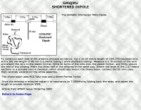 GM4JMU shortened dipole for 40 meters band. This article illustrates in detail how to build a resonant antenna for 7.030 MHz. Cut two 10.25-meter pieces of insulated wire, wind 40 turns of wire onto plastic tubing, and connect the wire to a central insulator using a choke balun built of RG174AU coax and a ferrite toroid. Once built, the antenna is adjusted by altering the wire length to produce the lowest Standing Wave Ratio (SWR) for best performance. The guide emphasizes careful building and adjustment for the best results.
 -
 Optimizing the impedance transformation and common-mode current suppression in antenna systems often involves selecting an appropriate balun. This project presents a **hybrid balun** design, combining characteristics of both voltage and current baluns to achieve superior performance, particularly when used with an antenna tuner. The design addresses issues like **common-mode current** on the feedline, which can distort the antenna's radiation pattern and introduce RFI in the shack. The construction details include winding techniques for the toroid core, component selection, and practical considerations for integration into an existing antenna system. Performance comparisons are drawn against conventional balun types, highlighting the hybrid balun's effectiveness across the HF bands. The resource provides insights into the current distribution and impedance matching properties, crucial for efficient power transfer and reduced SWR.
 -
 This drawing shows a simple 10 meter wire J-pole antenna designed for 28.4 MHz. It is a vertical, end-fed Zepp-style antenna made from common materials and intended for easy home construction. The main radiating element is a straight length of stranded copper wire, either 14 or 18 gauge, cut to about 16.5 feet. At the top, the wire is supported by an insulator, allowing the antenna to be hoisted vertically. The matching section is made from 450-ohm ladder line, approximately 7 feet 9.5 inches long, and shorted at the bottom. This matching stub transforms the impedance so the antenna can be fed with coaxial cable. The feed point is tapped about 6 inches above the bottom of the stub, with the shield and center conductor connected at the proper points. A choke balun is formed with five turns of RG-58 coax in a 4-inch diameter loop to help reduce unwanted RF on the feed line. The drawing notes that this antenna has about 0 dBd gain, similar to a dipole, but offers an omnidirectional pattern and low-angle radiation when installed high. Its main advantage is practical performance, simple construction, and effective coverage for 10 meter operation.
 -
 Constructing a compact, directional antenna for the 6-meter band presents unique challenges, especially for operators with limited space or those seeking portable solutions. This project details the build of a 50 MHz Moxon rectangle, specifically engineered for balcony or temporary mast deployment, using readily available materials from a typical hardware store. The design emphasizes ease of construction and portability, allowing for quick setup and breakdown. The antenna's dimensions are precisely calculated using _Moxgen_ software for 50.200 MHz, ensuring optimal performance. Key construction techniques include using aluminum U-channel for elements, fiberglass driveway markers for insulation, and cable ties for secure assembly. The guide provides detailed instructions for fabricating the driven element, reflector, and boom, including a clever method for creating foldable element tips for transport. Performance observations indicate a respectable front-to-back ratio, capable of reducing an S7 signal to S0 when pointed away, and a modest gain over a simple wire antenna. The design incorporates a ferrite bead choke balun at the feedpoint to mitigate common-mode current and reduce shack noise, a critical consideration for urban or apartment-based operations.
 -
 Presents a detailed construction guide for a 2-element _Moxon rectangle_ antenna optimized for the 10-meter band, designed by L. B. Cebik, W4RNL (SK). This resource demonstrates how to build a compact beam antenna using readily available hardware store aluminum tubing, fitting within a 12-13 foot width. It highlights the antenna's performance characteristics, including a gain comparable to a 2-element Yagi (11+ dBi) and a front-to-back ratio exceeding 20 dB between 28.3 and 28.5 MHz, with an SWR below 2:1 across the entire band. The design emphasizes direct 50-ohm coax connection without a separate matching system, though a 1:1 choke _balun_ is recommended. The guide provides practical advice on element construction, corner fabrication using L-stock or radius-bent tubing, and the critical side-to-side length adjustment for SWR optimization. It details the feedpoint assembly using a chassis-mounting coax connector and discusses element-to-boom plate options, including spar varnished plywood or LE plastic. The author's experience with a test model on a 20-foot mast confirms stable feedpoint characteristics and excellent performance even at lower heights. The document also includes insights into the antenna's free-space azimuth patterns, noting a broad forward lobe and significant front-to-back rejection. It contrasts the Moxon with traditional Yagis, positioning it as an effective, home-buildable alternative for compact sites or _Field Day_ operations, particularly beneficial during periods of increased 10-meter activity.
 -
 Demonstrates the construction and performance of an updated ZS6BKW multiband dipole, a variant of the _G5RV_ antenna, specifically designed for HF operation. The article details a real-world installation using 13.5m copper wire elements and 12.2m of 450 Ohm ladder line, configured as a sloping inverted-V with the apex at 10m and ends at 4m above ground. It covers the critical aspect of impedance matching, incorporating an 8-turn choke balun at the feedline transition to RG-58U coax to mitigate RF common mode current. Measurements confirm favorable SWR readings below **1.3:1** on 7.1 MHz, 14.11 MHz, 18.06 MHz, and 24.8 MHz, indicating effective resonance across 40m, 20m, 17m, and 12m bands. The installation also shows usable SWR dips on 3.55 MHz (5:1), 29.02 MHz (2:1), and 50.84 MHz (3:1), extending its utility to 80m, 10m, and 6m with an antenna tuning unit. Initial on-air results report clear reception of stations over **5000km** away, validating its DX potential.
 -
 One common challenge in antenna systems is mitigating common-mode current on the feedline, which can distort radiation patterns and introduce RF in the shack. This project details a 1:1 balun design that ingeniously avoids traditional ferrite beads, often a costly component, by substituting them with steel wool. The steel wool, when integrated into the balun's construction, effectively attenuates unwanted RF on the outer braid of the coaxial cable, ensuring that the antenna radiates efficiently and as intended. The construction involves winding coaxial cable through a PVC former, with the steel wool strategically placed to provide the necessary common-mode impedance. This method offers a practical and economical alternative for hams looking to build effective baluns without the expense or availability issues associated with ferrite cores. The design principles focus on creating a balanced feed to the antenna, crucial for optimal performance of dipoles and other balanced radiators. Experimentation with such designs can lead to improved field results, particularly for those operating with limited budgets or seeking innovative solutions for their antenna systems. The simplicity of using readily available materials like steel wool makes this a compelling build for many radio amateurs.
 -
 The "Largest YU Moxon" document details the design and construction of a substantial multiband Moxon antenna, primarily for 80m, 40m, and 20m operation. It presents specific design parameters derived from NEC-based simulations, including a 4-element 80m Moxon with 37 dB F/B and 7.81 dBi gain on a 47m boom, a 4-element 40m Moxon with a bidirectional pattern, and a 6-element 20m Moxon optimized for specific side lobes. The resource provides precise element lengths and spacing in meters for each band, alongside measured SWR results across the 3.650-3.800 MHz, 7.000-7.100 MHz, and 14.000-14.350 MHz segments. The construction narrative outlines the challenges and solutions encountered by the YU team, including the use of trees for support, the creation of "ugly" air-choke baluns from RG-58 cable wound on plastic bottles for each band, and the meticulous process of attaching wires to a rope boom. It documents the physical dimensions of the vineyard site (47 x 38m) and the azimuth orientation (340 degrees) chosen for the antenna. The document is distinctively useful for its practical insights into large-scale antenna deployment in a field environment, offering real-world SWR measurements and anecdotal performance reports from CQWW contest operations. It includes numerous photographs illustrating the construction process, the team members, and the finished antenna structure, providing visual context to the technical details.
 -
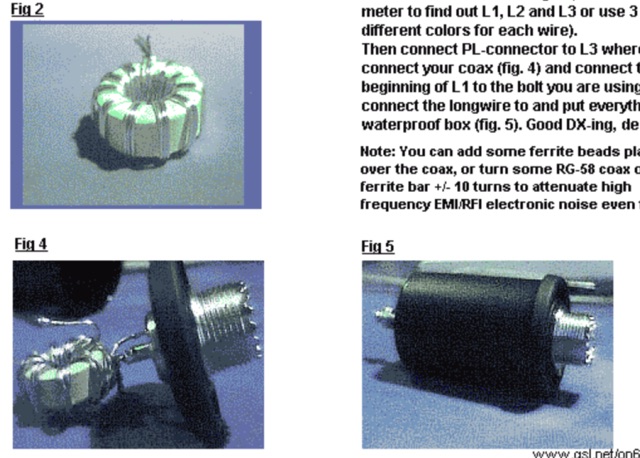 RF Choke to prevent hf currents on the feedline. This Magnetic Longwire Balun (MLB) makes it possible to efficiently use a coaxial lead-in cable with all forms of longwires, T-forms or other types of wire antennas, without the need for an antenna tuner.
 -
 RF Choke to prevent hf currents on the feedline or...1:1 Choke Balun, sometimes called the "UGLY BALUN"
 -
 Constructing a Lindenblad antenna for 137MHz NOAA satellite reception involves specific design considerations for optimal performance. The resource details the use of 4mm galvanised steel fencing wire, 300-ohm television ribbon cable, and wood/plastic components for the antenna structure. Key dimensions for a 137.58MHz-resonant antenna are provided, derived from the ARRL Satellite Handbook, specifying s, l, w, and d as 42, 926, 893, and 654mm respectively. The antenna is designed for Right Hand Circularly Polarised (RHCP) signals, requiring the four folded dipole elements to be tilted clockwise by 30 degrees. A significant aspect covered is impedance matching between the antenna's 75-ohm impedance and a typical 50-ohm receiver input. A twelfth-wave matching transformer, constructed from 117mm sections of 50-ohm RG-58 and 75-ohm RG-59 coax with a 0.66 velocity factor, is described. The article also addresses coaxial cable and connector selection, recommending 75-ohm Type-N connectors for RG-6 cable in professional setups and F56/F59 connectors for general use, while strongly advising against PL-259/SO-259 connectors for VHF. Strategies for mitigating Radio Frequency Interference (RFI) are discussed, including antenna placement to shield from local TV transmitters and the use of commercial or DIY band-pass filters, such as cavity resonators or helical notch filters, along with ferrite chokes on coaxial cables. Antenna orientation is explored, noting the Lindenblad's 'cone of silence' directly overhead and its maximized sensitivity towards the horizon. An experimental vertical tilt of 90 degrees is presented as a method to improve overhead reception and reduce interference from strong horizontal signals, particularly relevant in high RFI environments like the Siding Spring Observatory site.
 -
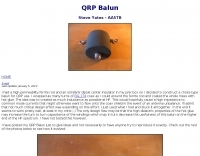 The QRP choke balun described utilizes a high permeability ferrite rod and RG-174 coax, aiming to present high impedance to common-mode currents across the HF spectrum. The construction involves winding as many turns of RG-174 as possible around the ferrite rod, then encapsulating the assembly with hot glue. This design prioritizes maximizing inductance to suppress unwanted shield currents, particularly in unbalanced antenna configurations. While the balun's effectiveness is subjectively reported as good, a potential design consideration involves the dielectric properties of the hot glue. This material could increase turn-to-turn capacitance, potentially reducing the balun's performance at higher HF frequencies, though this specific aspect has not been formally tested by the author, _AA5TB_. The project serves as an illustrative example of a practical, junk-box construction rather than a rigorously engineered solution. Photographs detail the evolution of the balun, from the initial winding process to its integration within a _B&W dipole center insulator_ and final camouflaged assembly.
 -
 Operating a ZS6BKW antenna often involves understanding its lineage from the _G5RV_ design, with specific modifications by ZS6BKW to optimize performance on several bands. Through computational analysis and field measurements, the antenna's dimensions were refined to allow operation on 10, 12, 17, 20, and 40 meters without an antenna tuner. For 80, 30, and 15 meters, a tuner is necessary, though efficiency on 30 and 15 meters is noted as not particularly high. The physical configuration consists of two 13.755-meter radiating elements fed by a 12.20-meter section of 450-ohm ladder line. Tuning the antenna on the 20-meter band is critical, and any deviation in the ladder line's characteristic impedance necessitates recalculating the element lengths. The design is also referenced in the 12th edition of _Rothammel's Antennenbuch_, page 219. Proper common mode current suppression is crucial at the transition from ladder line to coaxial cable. This can be achieved with a common mode choke, such as several turns of coax wound into a coil or over a ferrite toroid like an Amidon T130. While a 1:1 balun is an option, it may introduce issues.
 -
 Demonstrates practical solutions for reducing **Radio Frequency Interference (RFI)** in amateur radio operating environments, specifically addressing issues with PC monitors, receivers, and transceivers. The resource compiles advice from experienced operators regarding the selection and application of ferrite cores, including split cores and toroidal cores. It details specific material types like **43, 73, 75, and 77 ferrite**, outlining their effective frequency ranges for RFI suppression, such as 43 material for 30-400 MHz and 77 material for 2-30 MHz. The content provides part numbers for various ferrite products from manufacturers like Fair-Rite Products Corp, distributed by Amidon, and discusses their impedance characteristics across different HF bands. It compares the performance of various ferrite materials at frequencies like 4 MHz, noting that 75 material offers 27 ohms, 73 material 17 ohms, and 43 material just under 10 ohms. Additionally, it touches upon the use of bypass capacitors in conjunction with ferrites to create low-pass filters, emphasizing the importance of identifying common-mode versus differential-mode RFI paths for effective mitigation.
 -
 BIRD RF power measuring, new and used, HENRY RF power amplifiers (used HF amps), TOHTSU coaxial relays, SAMLEX power supplies, RFI chokes reduce interference, Parts parts, tubes, Used amplifiers, radios, antennas and accessories, Los Angeles, CA.
 -
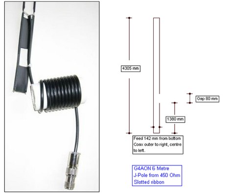 Based on original G2BCX design this J-Pole antenna for the six meter band is made with a homemade ribbon cable. The antenna shown in this article includes a coaxial cable choke feed to remove RF currents from flowing on the outer of the cable.
 -
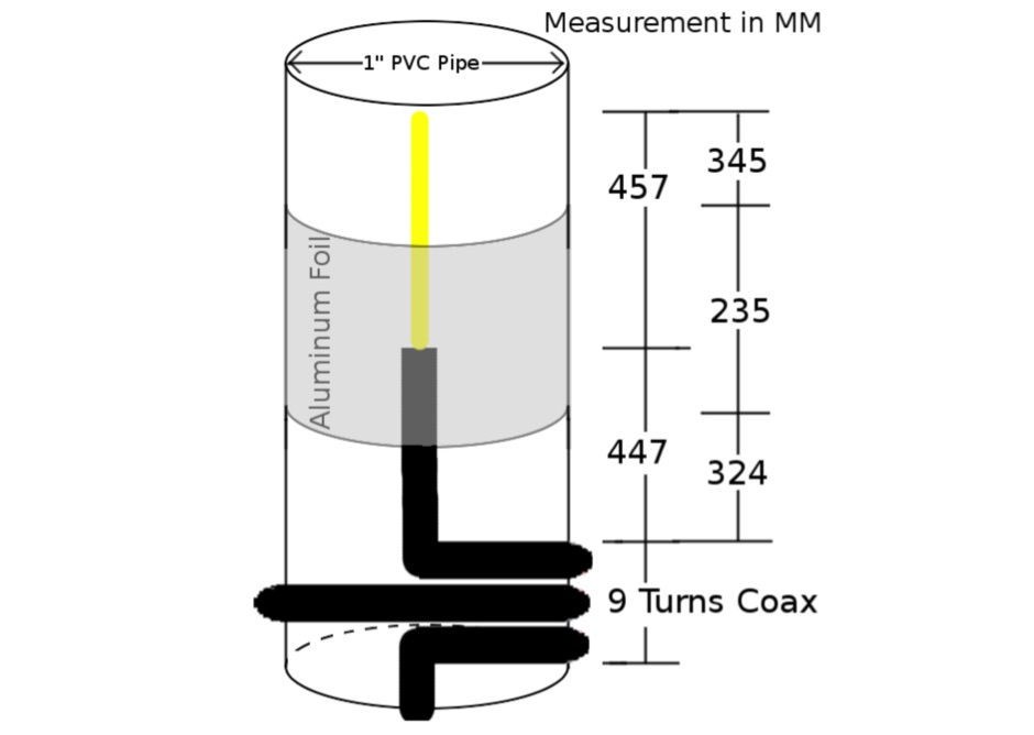 A homemade VHF/UHF vertical antenna made essentially with RG58 coax cable, with a 9 turns choke balun to prevent the shield acting as a RF Radiator.
 -
 The G5RV multiband HF antenna, designed by Louis Varney (G5RV) in 1946, is a popular compromise antenna offering good overall performance on most HF bands when paired with an external antenna tuner. The basic full-size G5RV measures 102 feet across the top for 80 through 10 meter operation and is fed at the center via a 34-foot low-loss feed-stub. This interaction between the radiating section and the feed-stub facilitates matching across 80-10 meters with a standard tuner, often eliminating the need for ladder line directly to the shack. The antenna's design center frequency is 14.150 MHz, configured as a 3/2-wave dipole on 20 meters, with its 102-foot length derived from long-wire antenna formulas. Construction details emphasize the matching section, which can be open wire, ladder line (window-type), or TV twin lead. Each type has a specific velocity factor (VF) affecting its physical length for an electrical half-wave on 14 MHz; for instance, open wire requires 33.7 feet (VF 0.97), ladder line 31.3 feet (VF 0.90), and TV twin lead 28.5 feet (VF 0.82). The article provides formulas for calculating these lengths and discusses the antenna's behavior on individual bands, from 3.5 MHz where it acts as a shortened dipole, to 28 MHz where it functions as two three-half-wave long-wire antennas fed in-phase. Practical construction notes include recommendations for vertical descent of the matching section, sealing the coax junction, providing strain relief, and winding a coaxial choke coil to mitigate common mode current. The resource also presents dimensions for double-size (204 ft) and half-size (51 ft) G5RV versions, along with their corresponding matching section lengths for various line types, making it a versatile reference for hams considering this classic wire antenna.
 -
 The Resonant Feedline Dipole (RFD) HF antenna design utilizes a single piece of coaxial cable and a stranded wire section, forming a 1/4-wavelength radiator. This configuration, based on a 1997 ARRL Handbook design (page 20.17), functions by RF traveling on the inside of the coax shield and returning on the outside, creating the second half of the dipole. A choke wound into the feedline prevents RF current from flowing back down the feedline. Construction details include using RG-58a/u coax for a 75m version, with a 1/4-wavelength section of stranded wire soldered to the center conductor. The document provides choke dimensions for RG-213, RG-8, and RG-58 coax across 3.5 MHz to 28 MHz, specifying cable length and number of turns. Dipole dimensions are also tabulated for frequencies from 3.6 MHz to 28.4 MHz, listing overall length and individual leg lengths. Field tests included deployment near Bryson City at 5 feet off the ground and as a sloper during WCARS Field Day in Asheville, yielding successful local and regional contacts.
 -
 Learn How - Winding your own RF Choke, Inductor Winding instructions
 -
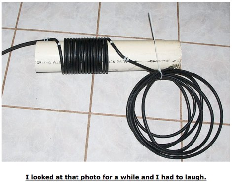 In this article K3DAV show a very simple way to make an RF choke coil that will remove your RF feedback troubles
 -
 The intrepid newcomer encounters common mode problems in a mobile environment. Implementing some common mode chokes will be possible to reduce interferences
 -
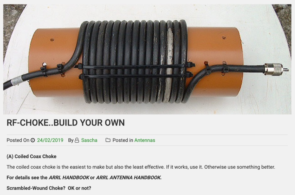 How to make an effective RF Choke. The coiled coax choke is the easiest to make but also the least effective. This article includes some general guidelines for winding coax chokes on a 10cm PVC pipe using RG-58 or RG-213 coax cable.
 -
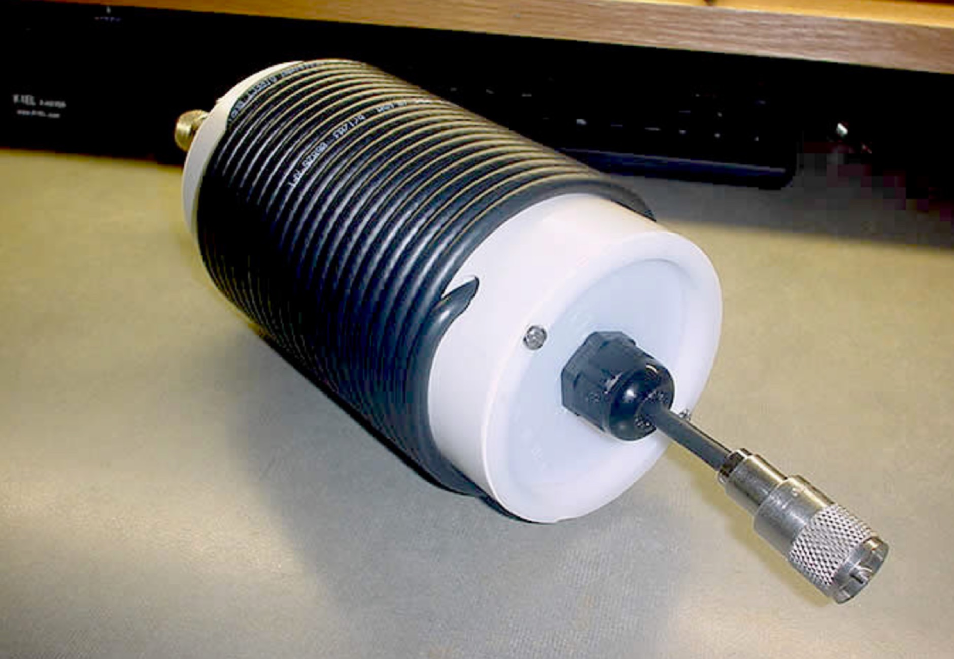 The main function of the Ugly Balun is to help eliminate rf currents from flowing on the outside of coaxial cable using the principle of choke action.
 -
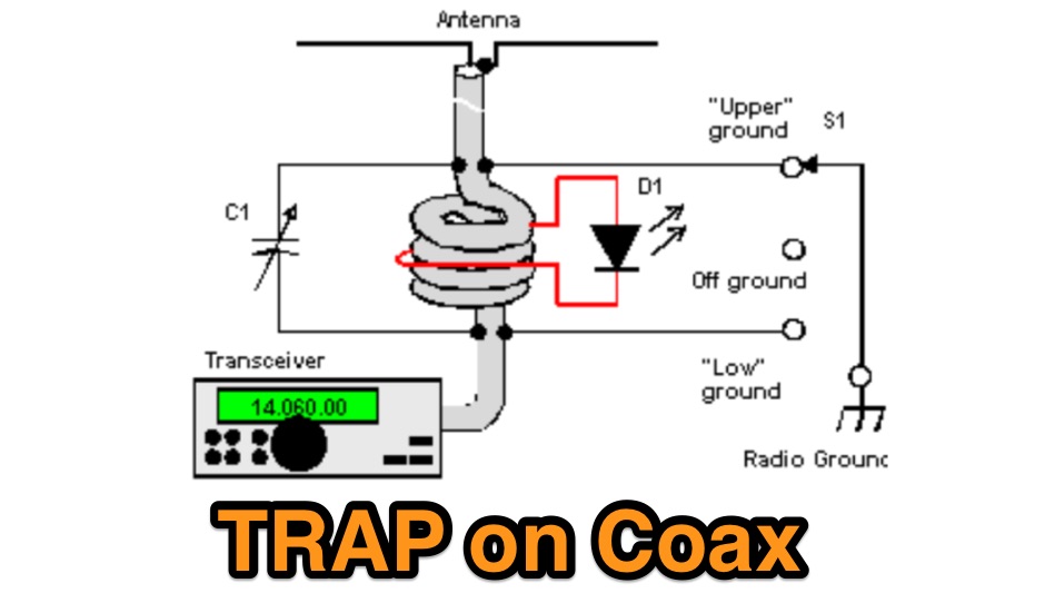 A trap on the coaxial cable, also known as choke, helps to eliminate the sneaking of the reflected RF- energy to the shack. The trap can be made from the coaxial cable that feeds the antenna
 -
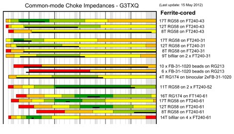 A chart presenting the results of impedance measurements made on a variety of common-mode choke implementations across the frequency range 1MHz to 30MHz by G3TXQ
 -
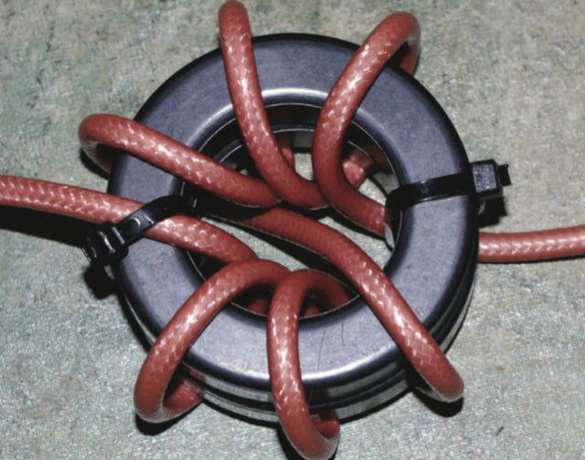 May 2015 Radcom Article on common-mode chokes that can be used for control cables, phone lines, but mostly on typical HF antenna systems. This article explain what common mode chokes does, why you meay need one, properties common mode chokes should have, how to build and measure performances.
 -
 TSC International produces soft magnetic sheet steel, custom-stamped and heat-treated to achieve optimal electrical characteristics for applications such as motors, generators, linear power supplies, and ballasts. The company's manufacturing process focuses on precise material engineering to meet specific performance requirements in various electrical systems. They also specialize in soft magnetic core materials essential for transformers, chokes, and inductors. These core materials are utilized in power supplies, lighting ballasts, signal conditioning circuits, inverters, and battery chargers, providing critical magnetic properties for efficient energy conversion and signal integrity. Located at 39105 Magnetics Blvd, Wadsworth, IL 60083-0399, TSC International provides contact via sales@tscinternational.com or phone at +1 (0) 847 249 4900, facilitating direct inquiries regarding their magnetic component offerings.
 -
 This resource provides fundamental guidelines for optimizing mobile amateur radio antenna installations. It addresses critical factors such as achieving an adequate ground plane, minimizing common mode current, and reducing ignition noise. Specific recommendations include mounting antennas on the vehicle's roof for superior radiation patterns and utilizing proper feedline routing to mitigate RF interference within the vehicle's electrical system. The content details the impact of antenna placement on Standing Wave Ratio (SWR) and overall radiated power, emphasizing the importance of a solid electrical connection to the vehicle chassis. It also discusses strategies for noise suppression, such as bonding body panels and employing ferrite chokes on power leads. The information presented is practical for hams seeking to improve their mobile station's efficiency and reduce RF-related operational issues.
 -
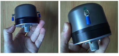 Presents a construction project for a 1:1 current balun, specifically detailing the _Sorbie Balun and Bottle Choke_ design. The resource outlines the winding technique, employing 4+4 turns of mini coaxial cable on a large ferrite core, and provides insights into the physical assembly. It includes specific material recommendations, such as the type of ferrite and coaxial cable, crucial for achieving the desired impedance transformation and common-mode current suppression. The content covers the practical steps involved in building the balun, from preparing the coaxial cable to securing the windings on the ferrite toroid. It also discusses the integration of the balun into an antenna system, emphasizing its role in maintaining pattern integrity and reducing RF interference in the shack. The resource offers a clear, step-by-step approach, making the project accessible for homebrewers. Illustrations and photographs accompany the text, visually guiding the builder through each stage of construction. The article concludes with performance expectations and considerations for deployment, ensuring the constructed balun functions effectively across the intended frequency range.
 -
 The _Sci.Electronics FAQ: Repair: RFI/EMI Info_ document, authored by Daniel 9V1ZV, provides a detailed analysis of computer-generated RFI/EMI, focusing on its impact on radio reception. It identifies common RFI sources such as CPU clock rates (e.g., 4.77 MHz to 80 MHz), video card oscillators (e.g., 14.316 MHz), and even keyboard microprocessors, all of which generate square-wave harmonics across HF and L-VHF regions. The resource outlines a systematic procedure for pinpointing RFI origins, including disconnecting peripherals and using a portable AM/SW receiver with a ferrite rod antenna to localize strong interference sources. The document categorizes RFI mitigation into shielding, filtering, and design problems, offering practical solutions for each. It recommends applying conductive sprays like _EMI-LAC_ or _EMV-LACK_ to plastic casings of radios, monitors, and CPUs to create effective Faraday cages, emphasizing proper grounding and avoiding short circuits. For filtering, the guide suggests using line filters, ferrite beads, and toroids on power and data lines, and small value capacitors (e.g., 0.01 uF for serial/parallel, 100 pF for video) to shunt RFI to ground. It also discusses the use of bandpass, high-pass, low-pass, and notch filters on the receiver front-end or antenna feed to combat specific in-band noise.
 -
 Manufacturer of transformers, inductors coils and chokes. Custom winding, EMI / RFI Filters, Antenna Windings on ferrite rod, Antenna Winding on phenolic. Any antenna coil designs.
 -
 The Tri-pole antenna, a clever modification of a standard dipole, allows for dual-band operation by integrating a third element. This design effectively shortens the overall dipole length by 10 to 20 percent, simplifying antenna rotation and offering a compact footprint. KK4OBI's article delves into the operational principles, using a 6 and 10-meter Tri-pole as a primary example, and provides comprehensive instructions for constructing any Tri-pole antenna within the 6 to 15-meter range. Key to the Tri-pole's performance is its off-center feed, necessitating a common mode choke at the feed point for optimal tuning and reduced noise. The author outlines a methodical approach to determining element dimensions, starting with a vertical element frequency calculated as 0.47 times the sum of the desired upper and lower band frequencies. This calculation, along with K-values derived from trend lines, guides the initial lengths for the horizontal arms, demonstrating how a 10m-6m Tri-pole can achieve a total horizontal length 78% shorter than a conventional 10-meter dipole. Tuning and balancing are critical, with the article detailing adjustments to arm lengths and the vertical element to achieve balanced SWR values, as validated through 4NEC2 simulations. Radiation patterns are analyzed at various elevations, showing gains around 5.7 dBi and favorable take-off angles for DX contacts. Construction details specify aluminum tubing dimensions, U-bolts, and an SO-239 connector, emphasizing the importance of a ferrite-based choke for wideband operation.
 -
 Constructing a dual-band antenna for 40 and 20 meters often involves compromises in size or complexity. This resource presents a compact _open sleeve dipole_ design that addresses these challenges by using 450-ohm ladder line and folded elements to achieve a total length of approximately **17.17 meters**, significantly shorter than a full-size 40-meter dipole. The design leverages electromagnetic coupling, where a primary radiator handles the 40-meter band, and a second conductor resonates on 20 meters without direct electrical connection. This configuration eliminates the need for traditional traps, loading coils, or switching components, simplifying construction and reducing potential loss points. The antenna is fed with RG-58C/U coaxial cable, and a common-mode choke is recommended at the feed point to suppress sheath currents, ensuring a cleaner radiation pattern and minimizing RF in the shack. The design is well-suited for portable operations, field deployments, temporary installations, and restricted urban environments where space is a premium, offering solid performance on both HF bands.
 -
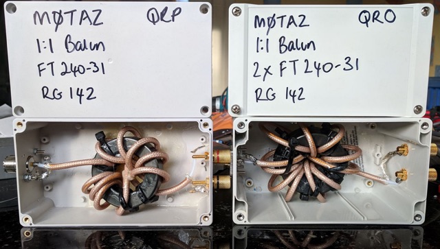 If you want to build your own common mode choke, this article explains how to measure the efficiecy of your choke before using it. In the examples has been used Amidon FT240-31 toroids.
 -
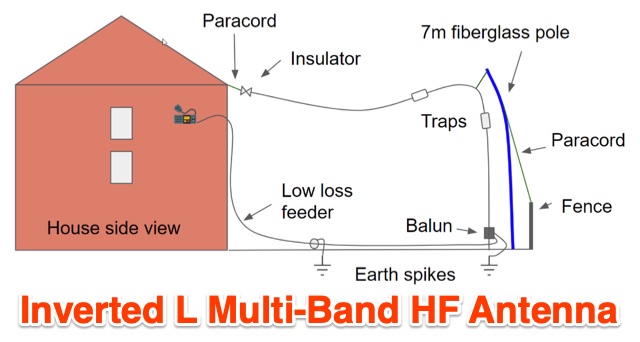 Discovering a solution for limited space, the inverted L HF antenna emerges as a stellar performer. Half the size of a dipole, it ensures optimal installation in restricted areas, maintaining superb transmission (TX) and reception (RX) characteristics. Spectrum Communications' multi-band version, featuring traps, proves even more space-friendly without compromising performance. A fiberglass pole offers sturdy support, while proper grounding, an RF choke, and occasional tuning contribute to a high-performing and reliable antenna system.
 -
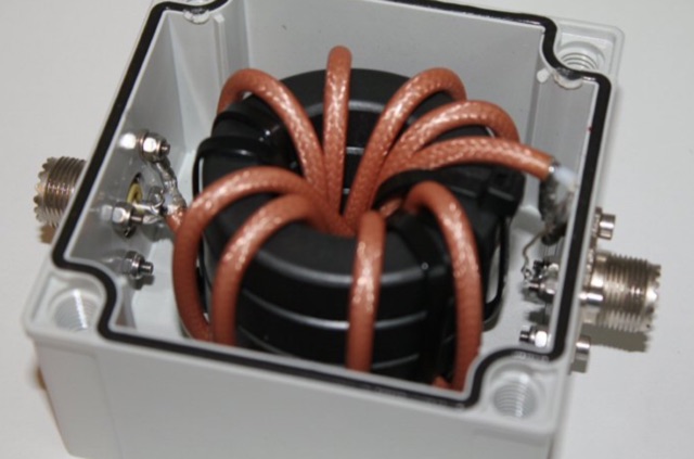 Home brewing a high performance, high power common mode choke for HF bands
 -
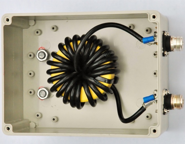 Choking balun for lower HF and MF bands. (1.8MHz - 10MHz). Requiring a choking balun to isolate the potential RF pick up on the coax cable as it runs past equipment such as computer within the radio room at lower HF and MF frequencies a simple method of winding RG58 coax onto a Powdered Iron Toroid Core was constructed.
 -
 Presents the construction and performance characteristics of the _Moxon Rectangle_ antenna, a compact, directional HF antenna design. It details the antenna's physical structure, emphasizing its robust build and ease of erection compared to traditional Yagis. The resource provides specific dimensions for building Moxons for the 10m through 40m bands, derived from _W4RNL_'s work, and discusses the critical element spacing for optimal performance. It also covers feeding the antenna with a simple choke balun and achieving a low SWR across the band. Compares the Moxon's performance to a two-element Yagi, noting its superior wind resistance and compact footprint. The author, _VK3BCY_, shares personal experiences with a 20m Moxon, reporting SWRs below 1.3 across the entire band and strong signal reports from DX stations with only 100 Watts. EZNEC Pro modeling data is included to illustrate gain and front-to-back ratios, confirming the antenna's high-performance claims. The article also briefly explores multi-band possibilities and reversible configurations.
 -
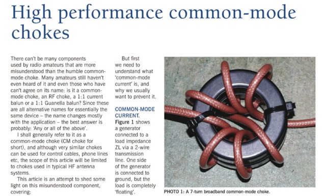 This article is an attempt to shed some light on this misunderstood component, covering topics like why you need a common mode coke, what it does, what properties it should have, ho to build one and how to measure its performance.
 -
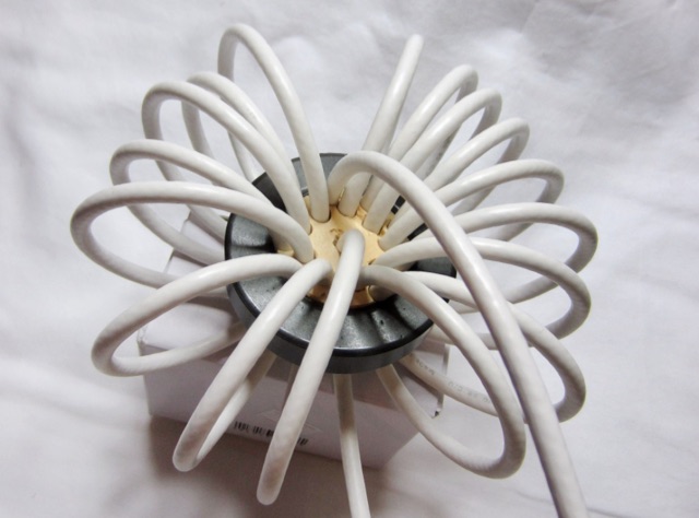 Common-mode chokes are useful solutions for RFI reduction. Winding a few turns of coaxial cable on the FT 240-31 toroid can reduced the noise below the received noise floor. In this article author measure different chokes
 -
 This article clarifies the roles of baluns, ununs, common mode chokes, line isolators, and impedance transformers in amateur radio. A balun decouples balanced antennas from unbalanced feed lines, preventing interference. Ununs serve a similar purpose for asymmetrical antennas. Common mode chokes and line isolators suppress common mode currents, reducing noise. Impedance transformers adjust antenna impedance to match feed lines but do not decouple or suppress common mode currents. Understanding these components is crucial for optimizing antenna performance and minimizing interference.
 -
 This is a power amplifier project for a RF 600W 1.8 MHz to 70 MHz linear amplifier including a Low Pass Filter. Projects includes schematics, pictures, PCD design, fans details, note on PA ferrite chokes and assembling instructions
 -
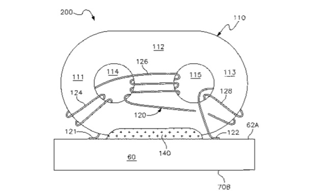 A reproduction test of a a binocular ferrite core and winds a total of 7 turns is a patented rf choke with an unusual winding, although this winding scheme reduces the inductance, it might result in a much larger bandwidth over which the choke has a sufficiently large impedance. The Author test this model by reproducing the choke.
 -
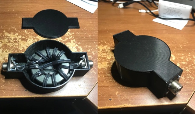 This article presents an RF Choke featuring an 11-bifilar turn winding of #14 house wire on a Fair-rite FT240-31 toroid. The choke is enclosed in a 3D-printed case from Thingiverse, though this may pose thermal concerns at higher power levels. With SWR concerns up to 30MHz, the author plans to employ two series chokes at the rig input for improved performance. This choke offers versatility for portable use, with potential mismatch resolution using an antenna tuner. Further testing is anticipated upon the arrival of new cables.
 -
 This comprehensive three-part guide examines baluns (balanced-to-unbalanced devices) and their critical role in ham radio antenna systems. The author explains how baluns prevent common-mode currents on feedlines, which can distort radiation patterns and cause unwanted RF in the shack. Various balun types are analyzed, including coiled coax chokes, ferrite-core designs (W2DU), and toroidal-wound versions (Guanella/Ruthroff). Construction techniques for 1:1, 4:1, 6:1, and 9:1 current baluns are provided with practical guidance on wire selection, winding methods, and ferrite core properties. The article emphasizes that proper balun implementation is essential for optimal antenna performance, especially with directional arrays.
 -
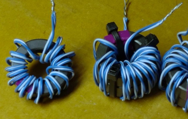 Chokes and isolation transformers are essential for receiving antennas to mitigate common mode current, which induces noise and interferes with signal quality. Common mode chokes, formed by winding feedline through ferrite cores, block unwanted current effectively. Proper selection of core material and winding turns ensures resonance near the operating frequency, reducing interference. Isolation transformers further minimize interference, crucial for multi-transmitter stations.
 -
 This article addresses the issue of unwanted RF in amateur radio setups and introduces a practical method to measure common-mode currents (CMC) using a homebuilt RF meter. The meter, constructed with readily available materials, measures unwanted RF on the coaxial cable shield by inductively coupling to the shield using a split-bead ferrite. The article provides detailed instructions on building the meter, interpreting measurements, and using ferrite chokes to mitigate RF interference. Emphasis is placed on the importance of verifying CMC levels and installing chokes to improve equipment performance.