Search results
Query: aerial
Links: 72 | Categories: 0
-
 K7SFN personal page with some projects and pictures of his aerials
 -
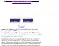 Chronicles the operational history of Cullercoats Radio, established in 1906 under _Marconi_ license, detailing its initial use of a spark-gap transmitter feeding a **200-foot** wooden mast. Documents the station's transition in 1915 to Marconi Wireless and a 1929 upgrade to a valve-type transmitter. Explains its later role as a British Telecom (BT) Maritime Radio Station, callsign GCC, serving as a receiving site with transmitting aerials at Hartley. Highlights the demolition of the commercial mast in 2000 and the site's subsequent sale. Features the Tynemouth Radio Club (GX0NWM) operating special event stations like GB4MPC for International Marconi Day from Marconi Point. Includes a historical QSL card confirming a QSO on **7.016 MHz** in 1936.
 -
 Basic magnetic loop antenna examples and loop aerials theory explained. This article inclued some interesting tricks on building magnetic loop antennas and an usefull excell sheet to help compute magneti loop antennas calculating power efficiency from 10 to 40 meters band
 -

-
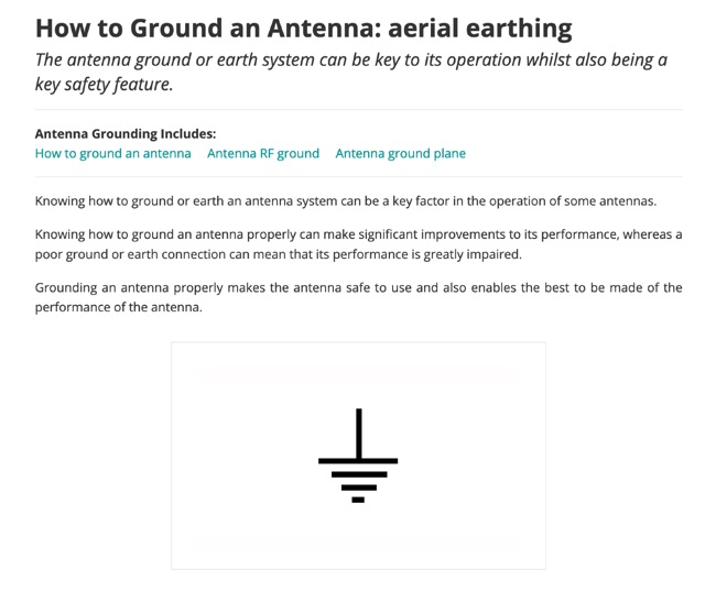 The antenna ground or earth system can be key to its operation whilst also being a key safety feature. This article is about grounding systems for antennas, covering different aspects of grounds made for antenna safety, or expressly for lightning or just to improve antenna performance, being ground an antenna component.
 -
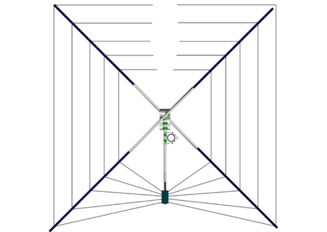
 The CobWebb antenna project is a compact, multiband HF solution ideal for amateur radio operators. Covering 14-28 MHz, it features a square dipole array with near-omnidirectional coverage and unity gain. This guide details a DIY approach, using a 1:4 current balun for impedance matching. Construction involves aluminum and fiberglass tubing, with optimized element tuning for SWR performance. Weather resistance improvements and resonance shift considerations are also discussed. Build your own CobWebb antenna for an efficient, space-saving HF experience.
 -
 This article discusses the Disk-Yagi antenna, also known as the "gun antenna," popularized by the video blogger KREOSAN. It explains the design, differences from standard Yagi-Uda antennas, and key features like the use of patch antennas and the integration of MIMO technology. The article covers the construction, tuning challenges, scaling issues, and provides insights on practical applications, such as optimizing signal performance with a 75-ohm antenna. It emphasizes that while DIY versions may vary, careful tuning and design are crucial for effectiveness.
 -
 The Slim-Jim is a bit of a classic - building one is almost certainly a rite of passage and you will be glad that you did: It is easy to make, fairly easy to tune and rolls-up for transportation.
 -
 Experimentin wire antennas on top band using several type of aerials. This includes a 40 to 160 meters EndFed Half Wave kite antennas and 160m/80m loaded vertical antenna.
 -
 Details the operational scope and maintenance requirements for the Gloucestershire Repeater Group's amateur radio repeater network. It outlines the financial obligations associated with site rent, electricity, insurance, and professional aerial maintenance, emphasizing the necessity of member support or donations for sustained operation. The resource provides information on accessing individual repeater systems via the site menu. It also announces the 2026 Annual General Meeting (AGM) details, including the date, time, and location at The Robins Nest, Cheltenham Town Football Club, noting the venue is shared with the Cheltenham Amateur Radio Association. The page highlights the availability of the repeaters to all licensed radio amateurs and details how to contribute to their upkeep through membership or direct donations.
 -
 The following is the third part of a three-part guide to help get started with HF, written by Charlie Davy – M0PZT
 -
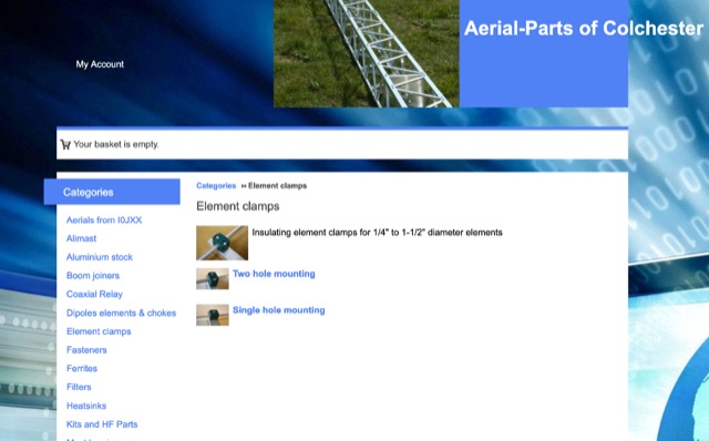 Online antenna parts store, providing many accessories for amateur radio antenna homebrewing. Boom joiners, aluminium parts, elements clamps, filters, ferrites, fasteners, plasti caps, dipole elements. Based in UL
 -
 The HB9CV antenna calculator aids amateur radio enthusiasts in designing antennas for VHF and UHF bands. By inputting the working frequency, users can obtain crucial dimensions like dipole lengths and distances. The tool, based on the HFSS antenna model, provides data on impedance, VSWR, and gain, optimizing front/back radiation ratios. It includes tips for fine-tuning using a Г-matching balun and compensating capacitor, ensuring effective performance and minimal VSWR for enhanced radio communications and direction finding.
 -
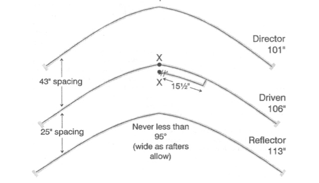 This design makes the most of having to put an aerial in the attic. This inverted-vee yagi is giving good results at GW0GHF. Directive gain is about 6 dBd. The front-to-back ratio is not brilliant, about 20 dBd.
 -
 Online antenna calculator for a basic 3 elements yagi uda directional antenna. The described antenna design offers a front-to-back ratio of at least 20 dB, a gain exceeding 7.3 dBi, and a bandwidth (SWR < 2) of approximately 7% around the center frequency. It has an input impedance of 50 ohms when using a straight split dipole, which can be substituted with a folded dipole of the same length, increasing the impedance to 200 ohms. A matching balun is required for coaxial feeder connection, and the boom should be made of a dielectric material, like wood.
 -
 A 5/8 λ antenna, often thought to be ideal for all frequencies, has unique characteristics that don't universally apply. First introduced for medium-wave radio, it works optimally at 225° antenna length over ideal ground, yielding high efficiency. However, at VHF and higher frequencies, it offers no advantage over other antennas due to real ground conditions and complex matching requirements. DIY calculators provide only rough estimates, useful as a starting point for simulations, not for precise builds.
 -
 Affordable full color QSL card printing. Premium quality offset printing with gloss, spot UV, and foil coatings.
 -
 This article details the author's process of designing and building a trap dipole antenna for the 17, 12, and 6-meter amateur radio bands using a Yaesu FT-450 transceiver. The antenna incorporates parallel-tuned circuit traps to enable operation across multiple bands without switching aerials. Key construction details, including coil and capacitor specifications, are discussed, along with the testing results, which include successful long-distance communications on the 50 MHz band. The article highlights the flexibility of home-built antennas and provides insights for amateur radio enthusiasts looking to optimize multi-band performance.
 -
 Method, Units of Measure, and the Dipole Standard of Reference. This article helps in understanding where does beam gain come from in directional aerials like in example Yagi antennas.
 -
 OM0ET manufacture high capacity variable air capacitor and tuning unit designed for Magloop antennas. OM0ET explains features and benefits of this antenna, such as easy assembly, wide frequency range, and improved efficiency. Ideal antenna setup for indoor or outdoor use, offering better QSO performance and radio listening experience. The author, identified as OM0ET, shares insights on the design and functionality of the equipment, making it a valuable antenna for portable operations.
 -
 The article explores the concepts of return loss, VSWR, and S11 within the context of microwave engineering, highlighting the confusion arising from their definitions. It clarifies that these parameters, while seemingly distinct, fundamentally describe the same phenomenon related to wave reflection and transmission in microwave circuits. The discussion emphasizes the historical context and mathematical relationships among these terms, revealing that their interpretation can vary significantly across different engineering disciplines. Ultimately, it advocates for a pragmatic approach to using these parameters based on familiarity rather than strict definitions.
 -
 The 4m Slim Jim antenna project provides a construction guide for a low-cost, high-performance aerial designed specifically for the 70 MHz FM band. This design achieves a 1:1 SWR across the 4m FM band with straightforward adjustment of the feed point, utilizing RG-58 coax. Its low angle of radiation contributes to effective signal propagation. Construction involves using plastic knitting needles as spreaders and a telescopic fishing pole for support, with components secured using two-part epoxy. Annealed bare single-core copper wire forms the radiating element. The setup process includes raising the antenna at least 3 meters above ground for tuning, adjusting the RG-58 feed point for optimal SWR, and then soldering connections. Waterproofing is achieved with yacht varnish. The design emphasizes low wind resistance for durability, making it suitable for exposed outdoor installations. A PDF construction diagram is available to supplement the written instructions.