Search results
Query: half wave end fed
Links: 82 | Categories: 2
-
 Constructing an End-Fed Half-Wave (EFHW) antenna offers a practical solution for HF operators seeking a multiband wire antenna without the need for extensive radial systems. This design typically employs a high-impedance transformer at the feed point, matching the antenna's inherent high impedance to a 50-ohm coaxial feedline. The article specifically details a 2012 approach, focusing on a transformer with a 49:1 turns ratio, which is a common configuration for EFHW antennas. The resource outlines the construction of a wire element cut for a half-wavelength on the lowest desired band, with specific coil arrangements enabling operation on harmonically related bands such as 40m, 20m, and 10m. It discusses the physical dimensions and winding details for the matching transformer, often utilizing a ferrite toroid core to achieve the necessary impedance transformation. The content provides insights into the operational principles and practical considerations for deploying such an antenna, including methods for tuning and optimizing performance across multiple amateur radio bands. While acknowledging that the presented information from 2012 may be superseded by newer insights, it serves as a foundational reference for understanding EFHW antenna theory and construction.
 -
 The ZS1J/B beacon operates on 28.2025 MHz with 5 Watts output to a half-wave, end-fed vertical antenna, initially installed in 1977 as ZS5VHF near Durban. The 10-meter transmitter is a modified 23-channel CB radio, and the identification keyer uses a diode matrix unit with TTL ICs from the same era. After relocation to Plettenberg Bay in 1993, the beacon has been in continuous service, with additional QRP transmitters later installed for other bands. In 1994, a single-transistor, 80-meter, 0.5-watt QRP transmitter with a half-wave dipole was added on 3586 kHz, followed by a 160-meter, 0.5-watt unit on 1817 kHz. A 30-meter, 0.5-watt transmitter was installed in 1996, operating on 10.124 MHz. In 2002, a 40-meter QRRP beacon on 7029 kHz, with an output of 100 microwatts, achieved DX reports up to 1100 km from ZS6UT in Pretoria. Best DX reports for the 80m and 160m beacons came from 9J2BO.
 -
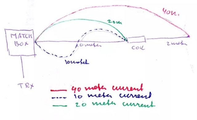
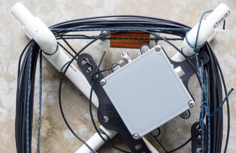 An interesting article on end fed half-wave wire antennas with a couple of original experiments. Author illustrate the role of the QRP matchbox, and a 40/20 meter antenna with a center stub making it a large bandwidth antenna for 40 and 20. Includes also an 80/40 end fed with the typical coil to make it available on 80 merts band.
 -
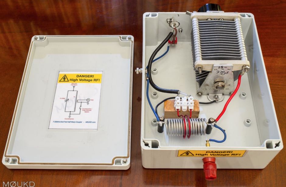 A home made end-fed half-wave antenna coupler with antenna lenght calculator and counterpoise calculator based on center frequency. Includes pictures and drawings along to antenna homebrewing instructions with a home made on air wound transformer
 -
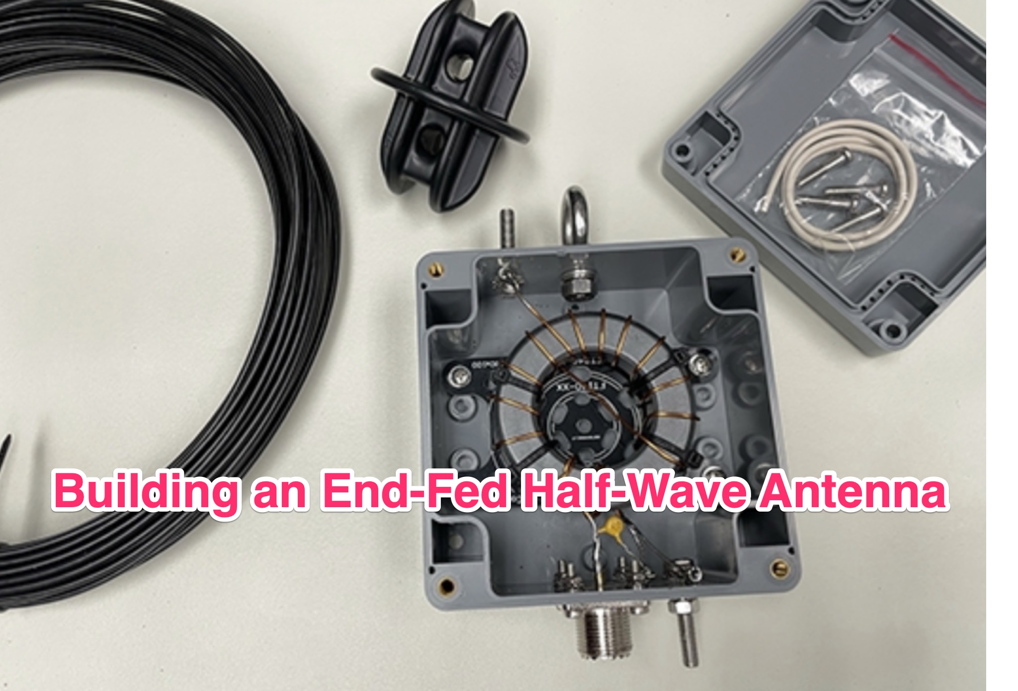 The ARRL's End-Fed Half-Wave (EFHW) Antenna Kit is an easy-to-build four-band antenna designed for 10, 15, 20, and 40 meters. Ideal for portable operations, it includes a 49:1 impedance transformer for compatibility with most transceivers. This project, detailed with step-by-step assembly instructions, involves creating a weatherproof enclosure and impedance matching network. The kit simplifies HF operations and supports multiple configurations, making it a versatile tool for amateur radio opertors.
 -
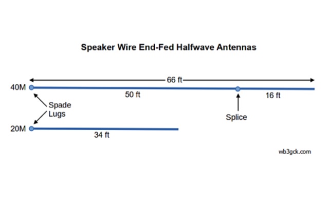 Author experiments end fed half wave antennas using common two conductore speaker wire, this article features a couple of end-fed halfwave wires for the 40M and 20M bands.
 -
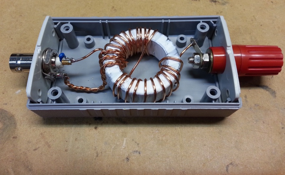 An end-fed half wave antenna matching unit made of 3:24 turns ratio on a FT140-43 toroid with a 150pF capacitor across the input.
 -
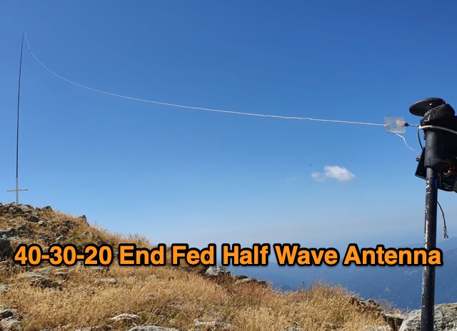 For my SOTA activities, i recently bought a QRP transceiver QRP SW-3B, which is a three-band QRP CW only for 40/30/20 m. So, i needed an antenna that would allow to use these 3 bands in SOTA portable activity. Already having some experience with the EFHW antenna, i decided to build one for 40/30/20m.
 -
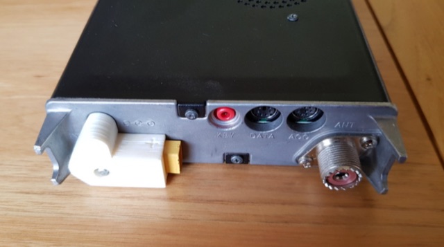 DC plug adaptor using an XT60 connector. 18650 Lithium battery 3 cell carrier, Three band end fed half wave antenna, XT60 chassis mounted flange.
 -
 Building an End-Fed Half-Wave (EFHW) antenna from a kit, as detailed by Frank Bontenbal, PA2DKW, with process photos by Bob Inderbitzen, NQ1R, offers a practical approach for hams. This specific kit, a collaboration between ARRL and HF Kits, targets 10, 15, 20, and 40 meters, making it a versatile option for HF operations. Unlike a center-fed dipole, the EFHW is a half-wavelength antenna fed at one end, which simplifies deployment, particularly for portable use. The construction guide meticulously outlines the assembly of the 49:1 impedance matching network, crucial for transforming the antenna's high impedance (around 2,500 Ohms) to a transceiver-friendly 50 Ohms. Steps include preparing the enclosure by drilling holes for the coaxial connector and antenna connections, followed by the precise winding of enameled copper wire onto a toroid to create the transformer. The guide emphasizes careful insulation removal and soldering for reliable connections. Final assembly involves integrating a 100 pF capacitor for higher band compensation, soldering the transformer's primary and secondary sides, and conducting SWR tests with a 2K7 resistor or a half-wavelength wire. The document also provides examples of wire lengths for different bands, such as 16 feet for 10 meters or 66 feet for 40 meters, demonstrating the transformer's adaptability for various half-wavelength configurations.
 -
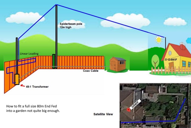 The author reflects on expanding their antenna for 80m coverage during lockdown. They extend the End Fed Half Wave (EFHW) using a Spiderbeam pole and "cheating" by dog-legging across their garden. Despite challenges, they achieve coverage for multiple bands with minimal cost. Practical Wireless features EFHW antennas, including a pre-made 20m EFHW extended for 40m.
 -
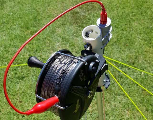 Experimentin wire antennas on top band using several type of aerials. This includes a 40 to 160 meters EndFed Half Wave kite antennas and 160m/80m loaded vertical antenna.
 -
 The 80-meter Skyloop antenna, a top-performing HF antenna, excels in weak signal work, low-noise operation, and omnidirectional coverage. Ideal for fixed stations, it delivers strong performance at low power, outperforming many alternatives, including 80m half-wave end-fed antennas. Requiring significant space for deployment, it’s well-suited for NVIS and groundwave use. Though not portable, it’s cost-effective and durable, with minor maintenance needs. Tuning may require adjustments for optimal resonance. It’s a standout for base stations, though a lighter portable version could enhance its versatility.
 -
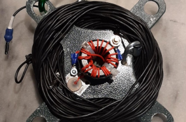 How to Design and Build a Field Expedient End-Fed Half-Wave Antenna for 20m, 40m and 80m. This Shorty 80m EFHW comprises a 49:1 autotransformer (to match the very high impedance at the end of a half-wave wire), a half-wavelength wire for 40m (also a quarter-wavelength for 80m), a loading coil and a short tail wire. The coil and the short tail wire (about 6 feet) make up the other quarter wave on 80m.
 -
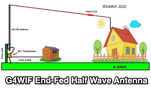 Opting for a visually appealing inverted L configuration, G4WIF anchors the End Fed Half Wave antenna to an old clothes line pole, seeking cost-effectiveness in their endeavor. Despite initial misconceptions about transformer components, a £7.95 investment in a T240-43 toroid and DIY mounting container resolves the issue. Reflecting on commercial alternatives, G4WIF's homemade solution proves both economical and sufficient for their amateur radio needs.
 -
 There are quite a few recipes for building a suitable transformer for an end fed half wave antenna (EFHW), but I was never sure I really understood the main principles. So, I wound a bunch of transformers, made measurements on them using my NanoVNA, learned how to get what I really wanted out of the VNA measurements, and in the process discovered how to build better transformers and be able to predict what they will do
 -
 This document details the construction of a multi-band end-fed antenna, suitable for situations with limited space for larger antennas. The design utilizes a 1:49 to 1:60 impedance transformer to match a half-wave wire antenna fed at one end. Compared to a traditional dipole, this antenna resembles a highly unbalanced Windom antenna with one very long leg and a virtual short leg. The design eliminates the need for radials but relies on the coax cable shield for grounding. The document recommends using at least 10 meters of coax and installing a common mode filter at the entry point to the shack for improved performance.
 -
 A medium power End Fed Half Wave Antenna coupler, specifically tuned to the QRP frequency of 7030 kHz. Constructed from coil stock and capacitors, it achieves an impedance ratio of 64:1. The coupler has proven effective for power ranges from 2 to 100 Watts on the 40m band.
 -
 The GAWANT Antenna, or Shinagawa Antenna is an half-wave vertical end-fed in a FT817-friendly package
 -
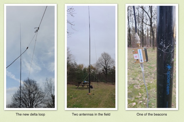 Intrigued by a German OM positive experience with a 20m delta loop, the author replicated the design, noting its favorable 50-ohm impedance compared to their 40m version. Testing against a vertical EFHW, the delta loop excelled within EU but lagged at longer distances. Despite needing more testing, the user leaned towards the EFHW for its overall performance and practicality.
 -
 The article describes the construction of a 1:49 impedance transformer designed to match the high impedance (around 2500Ω) of an end-fed half-wave (EFHW) dipole antenna to the 50Ω impedance of a typical transceiver. The EFHW is a popular portable antenna due to its simple construction, but feeding it can be challenging compared to a center-fed dipole. The transformer was built using an FT240-43 ferrite toroid core, with 2 primary and 14 secondary windings for a 1:49 impedance ratio. A capacitor was added in series with the primary winding to improve performance at higher frequencies. The author compared versions with one and two cores, and found that 100pF worked best for the single core design while 200pF was optimal for the dual core transformer.
 -
 This article explores the conventional wisdom about antenna height in amateur radio operations, challenging the common belief that "higher is always better." Through practical examples and computer modeling, it examines how low-height antennas like Beverage antennas, VP2E, and End-Fed Half Wave (EFHW) configurations can perform effectively in various scenarios. The analysis includes radiation patterns and efficiency considerations for antennas at different heights, particularly focusing on portable operations. The article demonstrates that while height affects antenna performance, lower installations can still provide practical and efficient solutions for specific applications, especially in portable and QRP operations.
 -
 Andrew Georgakopoulos, SV1DKD, modeled the End-Fed Half Wave (EFHW) antenna using MMANA-GAL software. He evaluated the EFHW-8010-2K from Myantennas.com for field operations, comparing it to random wires, OCFD, and dipole antennas. His results showed similar performance to OCFD, confirming EFHW's practical feeding advantage but with potential high-voltage risks at the feed point
 -
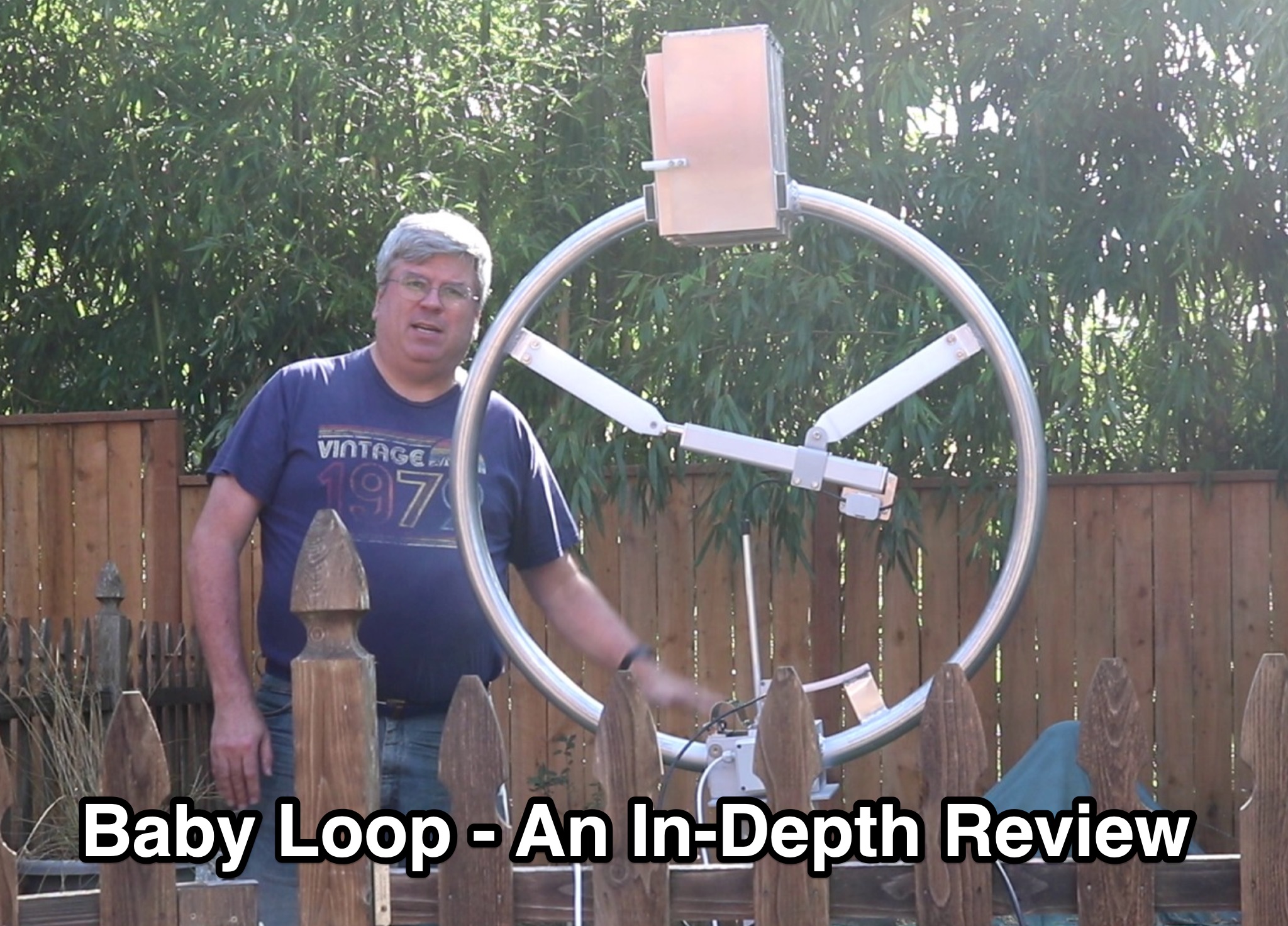 This article provides an in-depth review of the Ciro Mazzoni Baby Loop Ham Radio Antenna. The author, a ham radio operator, compares this magnetic loop antenna with his usual End Fed Half Wave antenna, discussing the performance and installation considerations. The post explains the concept of loop antennas, resonating frequencies, and the benefits of using a small loop antenna with a capacitor for optimal operation. If you are looking for information on magnetic loop antennas and their effectiveness in restricted spaces, this review offers valuable insights and practical experiences for ham radio operators.
 -
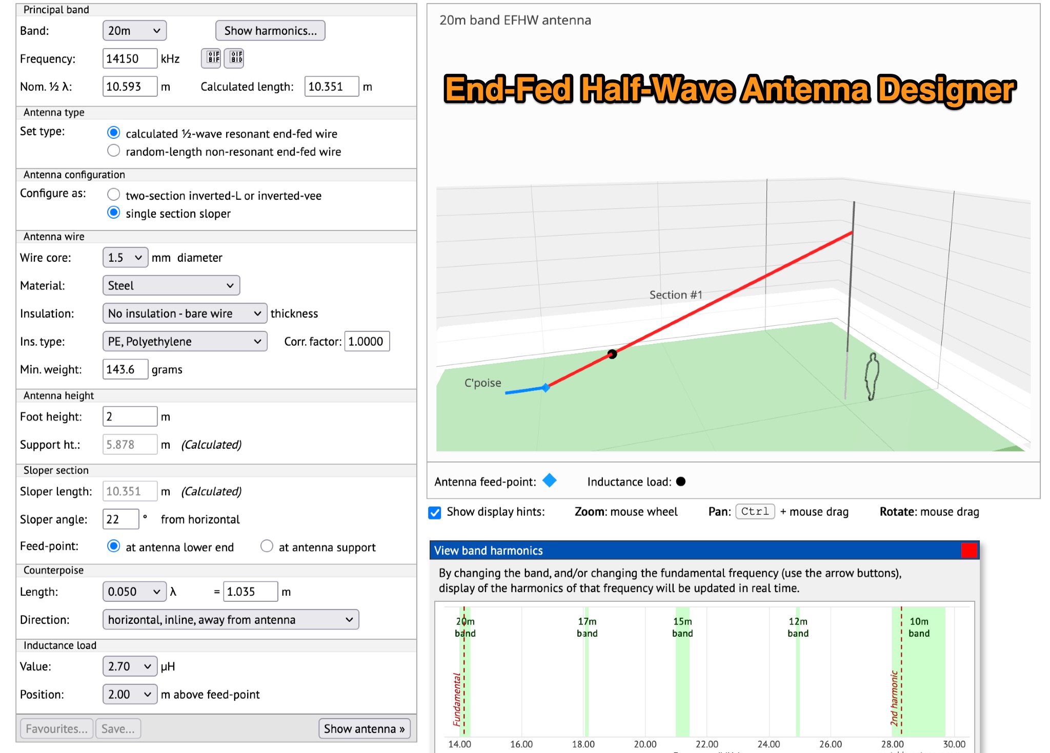 This page provides guidance on designing an End-Fed Half-Wave (EFHW) or Random-Length antenna for amateur HF bands, such as 80 or 40 meters. The content explains how to optimize the antenna for multi-band use and match it to a 50-ohm system using an unun. Hams can generate radiation patterns, VSWR charts, and antenna current diagrams for their customized antenna designs. Understanding how antenna dimensions affect performance is essential for successful field operations. The page caters to ham radio operators looking to build efficient and effective HF antennas for their stations.
 -
 This page delves into the debate surrounding the End-Fed Half-Wave (EFHW) antenna, exploring whether it is truly a multiband antenna without the need for a tuner. The author investigates the claims and criticisms surrounding these popular antennas, discussing their resonance on various bands and their efficiency for DXCC achievements. The content is valuable for hams interested in understanding the capabilities of EFHW antennas and their performance across different HF bands, with a focus on practical usage and real-world results.
 -
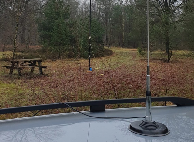 PH0NO conducted field tests comparing a mobile antenna (DX-UHV) to an end-fed half-wave wire. Results on 20m showed the end-fed wire outperforming the mobile antenna, with a significant difference in signal strength. On 40m, the end-fed wire surpassed the mobile antenna in spots and reach. While the mobile antenna is more practical, the end-fed wire offers superior performance. Further testing is planned.
 -
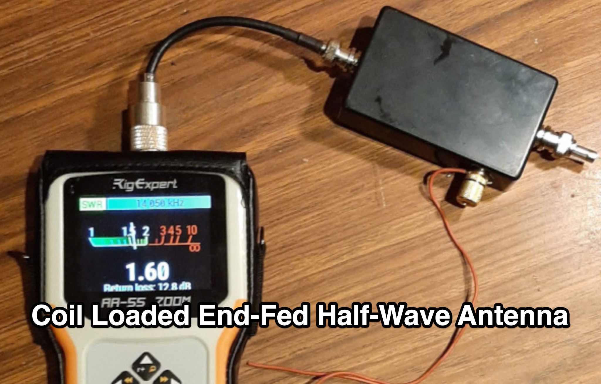 This page discusses the CLEFHW (Coil Loaded End-Fed Half-Wave) antenna, a portable variation of the popular EFHW design for ham radio operators. The article explains how the CLEFHW allows for backpack portable operation without the need for trees or poles, making it ideal for POTA activations and rapid deployment scenarios. The author details the design, optimization for 20m band, and compares efficiency to full-length wire antennas. Suitable for hams interested in portable antenna solutions and quick setup options for amateur radio activities.
 -
 This article presents a novel Top Loaded End-Fed Half-Wave (TLEFHW) antenna design for 20-meter ham radio operation. The antenna features a compact 14-foot vertical radiator with a capacitance hat configuration, eliminating the need for radials or ground systems. Using EZNEC modeling and field testing, the design achieves a 1.5:1 SWR across the 20m band with a 4.11 dBi gain. Key features include quick deployment, lightweight construction, and directional radiation pattern with 110-degree beamwidth. The design, while requiring a 45-foot footprint due to the top hat, offers an effective portable solution for amateur radio operators seeking a no-ground, no-tuner 20m antenna option.
 -
 The Zeppelin antenna, a J-type design, is presented as a two-band HF dipole, offering independent operation on harmonically related frequencies. This resource details its electrical configuration, comprising a half-wave radiator end-fed by a quarter-wave matching section, and explores its historical evolution from early Zeppelin airship applications to modern amateur radio use. The article specifically examines how a Zepp antenna tuned to 28.4 MHz (10 meters) exhibits a harmonic relationship with 15.4 MHz (20 meters), noting a frequency ratio of approximately 1.84:1, which deviates from a perfect 2:1 due to factors like elevation, wire separation, velocity factor, and end-effect. Antenna modeling results, including SWR sweeps at 28.4 MHz (1.1 SWR) and 15.4 MHz (1.6 SWR), are provided through Graph 1 and Graph 2, illustrating the antenna's performance across these bands. Current distribution patterns for both the 28.4 MHz (second harmonic) and 15.4 MHz (first harmonic) operations are visually represented in Figure 2 and Figure 3, respectively. The author also includes a 4NEC2 model's "Symbol Conversion file" definitions and calculated #14 wire dimensions for achieving resonance at 28.4 MHz, with the antenna positioned at a height of 33 feet. The discussion further highlights the antenna's versatility, suggesting its potential as a single-band, center-fed, 15.4 MHz half-wave folded end dipole when fed at a specific low current point. This analysis provides practical insights into constructing and optimizing a multi-band Zepp antenna for HF operations, emphasizing its unique harmonic characteristics and physical compactness.
 -
 Constructing a **J-Pole antenna** from 450 Ohm ladder line for 2-meter (144 MHz) and 70-centimeter (440 MHz) operation involves specific calculations and assembly steps. The design, based on an earlier KD6GLF concept using 300 Ohm twinlead, features a ¾ wavelength radiator and a ¼ wavelength matching stub, functioning as an end-fed half-wave antenna without requiring ground radials. It offers a gain of 2.4 dB over isotropic. The resource provides the formulas for determining the lengths of the ¾ wave radiator and ¼ wave stub, incorporating a velocity factor of 91% for 450 Ohm ladder line. For 146 MHz, the radiator measures 55 3/16 inches and the stub 18 3/8 inches. Construction details include cutting a 57¾-inch piece of ladder line, stripping 4 inches from one end, and attaching a 24-inch section of RG58 or RG8X coax with a 3-5 turn RF choke. SWR adjustment is achieved by sliding a shorting bar or by incrementally trimming the elements at a 1:3 ratio (stub to radiator). The goal is a 1:1.1 SWR at 146 MHz, which typically yields 1:1.2 at 446 MHz. The article also discusses power handling, noting that while 10-15 watts is fine, 50 watts may increase SWR to 1:2.1, and advises keeping the antenna away from other objects to prevent coupling and SWR degradation.
 -
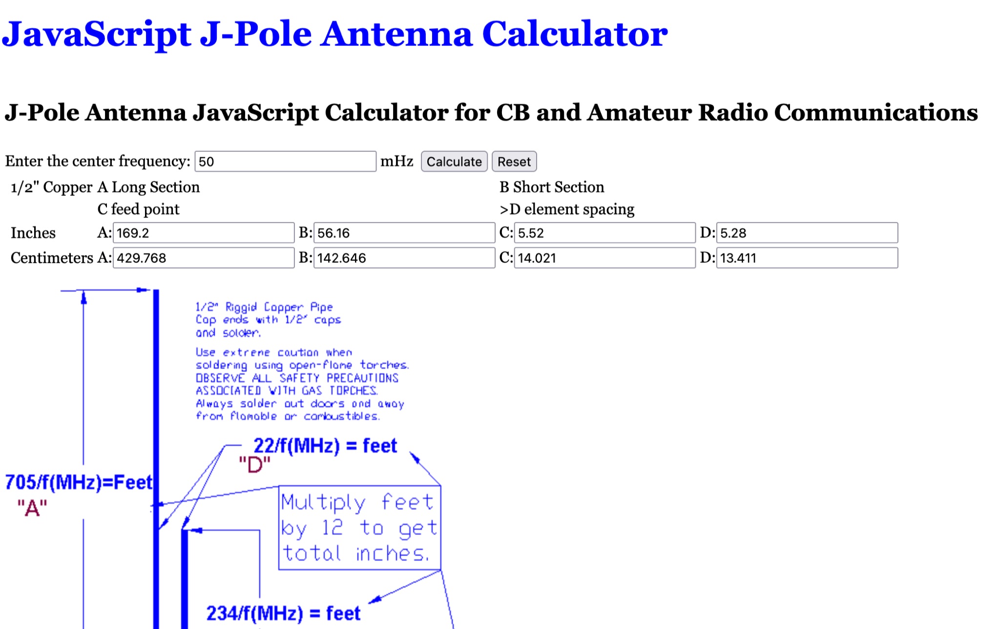 This page provides a detailed guide on the J-pole antenna, an end-fed half-wave antenna matched to the feedline by a quarter-wave transmission line stub. It covers the characteristics, construction materials, feeding options, and mounting considerations for optimal performance. The information is useful for hams or amateur radio operators looking to build and set up a J-pole antenna for improved transmission and reception.