Search results
Query: invert v
Links: 119 | Categories: 1
Categories
-
 Ham radio antennas and electronics, specialized in 1/2 wave dipole, OCF dipole, windom, full wave loop, end fed, inverted L, portable end fed antenna, long wire, SWL antenna, fan dipole, multiband dipole, G5RV and military antennas.
 -
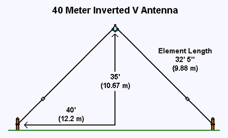 This 40 meter Inverted V antenna was tested and tuned at a height of 35 feet and proved excellent results. The ends of the antenna are about 11 feet above the ground. Article and video available
 -
 A short dipole wire antenna for 40 meters band. It is a folded dipole that do not make use of coils and can be used either in horizontal or inverted V configuration
 -
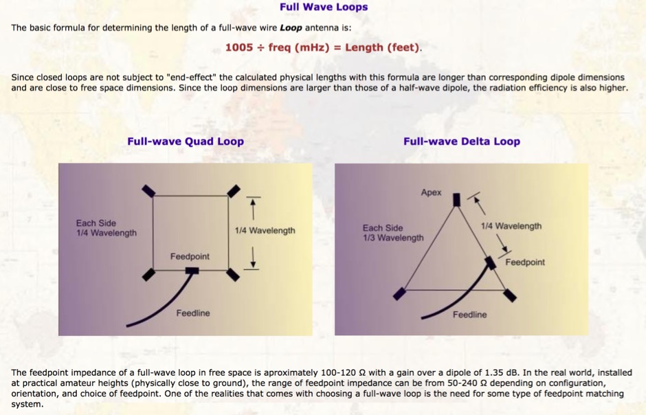 A javascript online calculator for popular wire antennas, from the standard easy to build flat-top dipole, to the inverted V dipole, but also the Quad Loop, and the equilateral delta loop antenna
 -
 This article describes a simple Inverted L antenna for the HF bands designed to work on 80m, 40m, 30m and 20m
 -
 An inverted triangle Delta Loop Antenna for the 40 meter band made with aluminium pipes, each element is 14,2 meters including a home made aluminium mount.
 -
-
 Dimensions for the inverted V antenna from 160 to 2 meters by N6JSX
 -
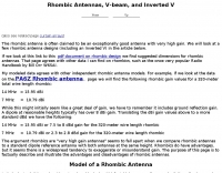 The rhombic antenna is often claimed to be an exceptionally good antenna with very high gain. Modelling rhombic antennas
 -
 A very efficient 80 meter Counterpoise antenna designed to reduce ground losses from inadequate radial systems beneath inverted L antennas, a project by DM2GM and DM4IM based on the original K2AV antenna concept.
 -
 This project details the construction of a **full-sized 40-meter vertical antenna**, born from a renewed interest in 7 MHz operation and a desire for improved effectiveness over simple dipoles. The author, K5DKZ, initially focused on VHF experimentation, which provided an inventory of aluminum tubing and fiberglass spreaders for this endeavor. Before this vertical, K5DKZ utilized an 80/40 meter inverted-vee trap dipole and a 40-meter broadband dipole, but now primarily uses a pair of full-sized, phased, quarter-wave verticals spaced 35 feet apart for serious 40-meter work. The construction involves a base-heavy design for stability, using a 44.5-inch section of 1-1/4 inch steel TV mast driven into 1-3/8 inch aluminum tubing, insulated by a 105-inch section of Schedule 40 PVC pipe. The assembly reaches 31 feet, close to the 32 feet required for a quarter-wavelength on 40 meters, with fine-tuning achieved by winding wire onto a fiberglass spreader. The design is explicitly presented as a foundation for a two-element 40-meter Yagi beam, outlining modifications like substituting aluminum for steel in the base and using an inductive hairpin match for the driven element. The article also discusses tuning considerations for a large 40-meter beam, noting the 100 to 200 kHz upward frequency shift when raised, and suggesting methods for installation on a tower. The author emphasizes the cost-effectiveness and good performance of the monopole approach, especially when multiple verticals are needed.
 -
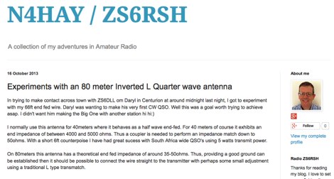 Experiments with an 80 meter Inverted L Quarter wave antenna
 -
 The Elecraft K2 transceiver requires specific modifications for optimal soundcard digital mode operation, particularly for PSK31. The original article, circa 2001, details initial challenges with manual PTT and speech compression settings. A key modification involves adding headphone audio and a compression disable signal to the K2's microphone jack, utilizing pins 4 and 5. The **COMP0** signal, active low, is shorted to ground via a non-inverting open collector switch circuit, comprising two resistors and two transistors, mounted on the SSB board near U3. This circuit provides effective control of an analog signal line with good noise immunity. The switchbox itself repurposes a computer COM port switch, using only two of its original connectors and four of the nine poles. It integrates a microphone preamplifier, a PTT circuit built with 'flying leads' construction, and RCA jacks for soundcard connections. A trimpot adjusts the audio drive to the K2. The central DB9 connector links to the K2's mic connector via a shielded RS232 serial cable, ensuring proper grounding and signal routing. An external footswitch PTT jack is also included. Further enhancements include a **noise-canceling microphone** preamp based on a QST December 2000 article, adapted for Heil mic elements. This preamp, built with pseudo-Manhattan style construction, provides a gain of approximately 2 by changing emitter resistors (R9 and R16) from 680 ohms to 330 ohms. A 10-ohm series resistor and 47 µF capacitor on the +5V supply mitigate noise spikes.
 -
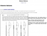 Sleeve baluns are normally used at VHF and higher. As a general rule, they are not practical at HF. The balun can be inverted and used as a skirt to form part of the antenna element
 -
 A simple to build full length 20/40 dipole antenna to be used in inverted vee configuration
 -
 Demonstrates the operational status and reception reports for the SK6RUD/SA6RR QRPP beacons, which transmit on 478.9 kHz, 1995 kHz, 10.131 MHz, and 40.673 MHz. These beacons utilize extremely low power, with the 630-meter beacon operating at approximately 0.1 watt ERP into an L-antenna, showcasing the potential for long-distance contacts under favorable propagation conditions. The site details the specific frequencies and antenna types employed, such as a vertical at 500 kHz and a 1/4 vertical for higher bands. The resource compiles over 10,530 reception reports from amateur radio operators worldwide, logging details such as date, time, band, RST signal report, locator, distance, and receiver setup. Notable long-distance reports include a 500 kHz reception by AA1A-Dave from 5832 km in 2008 and a 10.133 MHz reception by ZL2FT-Jason from 17680 km in 2010, illustrating the global reach of these low-power transmissions. Each log entry provides specific equipment used by the reporting station, including transceivers like the Yaesu FT817, ICOM IC-7300, and various antenna configurations such as coaxial mag loops, inverted Ls, and end-fed wires. The primary objective of the SK6RUD beacons is to challenge conventional notions of power requirements for effective two-way communication, proving that contacts over significant distances are achievable with minimal output. The site also includes a submission form for new reception reports, fostering community engagement and continuous data collection on propagation phenomena across different bands. The detailed logs offer practical insights into real-world propagation characteristics and the efficacy of QRPP operations.
 -
 Dipole, inverted V, full wave loop and grond plane antenna quick reference plans
 -
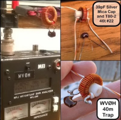
 The resource details the construction of a multiband trap-style Inverted-V antenna designed for operation on 3.5 MHz, 7 MHz, 14 MHz, 21 MHz, and 28 MHz. It presents specific winding data for the traps, including the number of turns, wire gauge, and coil former dimensions, crucial for achieving resonance on the target bands. The document provides a parts list and a diagram illustrating the antenna's physical layout and trap placement. It outlines the process for building the traps using PVC pipe formers and specifies the required capacitor values for each trap. The design emphasizes a practical approach to achieving multiband operation with a single feedline, a common goal for HF operators with limited space. The document includes a table with antenna segment lengths for each band, allowing for precise replication of the design. It also offers insights into tuning and adjustment, ensuring the antenna performs optimally across the designated amateur radio bands.
 -
 Manufacturer industrial and consumer power supply products including switching power supplies, solar panels, solar charge controllers, inverters.
 -
 TSC International produces soft magnetic sheet steel, custom-stamped and heat-treated to achieve optimal electrical characteristics for applications such as motors, generators, linear power supplies, and ballasts. The company's manufacturing process focuses on precise material engineering to meet specific performance requirements in various electrical systems. They also specialize in soft magnetic core materials essential for transformers, chokes, and inductors. These core materials are utilized in power supplies, lighting ballasts, signal conditioning circuits, inverters, and battery chargers, providing critical magnetic properties for efficient energy conversion and signal integrity. Located at 39105 Magnetics Blvd, Wadsworth, IL 60083-0399, TSC International provides contact via sales@tscinternational.com or phone at +1 (0) 847 249 4900, facilitating direct inquiries regarding their magnetic component offerings.
 -
 Modeling compact 160 meter antennas, inverted L, half wave dipoles and linearly loaded dipole
 -
 The NB6Zep Antenna, an electrically shortened 80-meter end-fed wire, addresses space constraints for low-band operation by integrating two loading coils into a 37-foot wire. This design, modeled with _EZNEC_, explores configurations like the quarter-wave sloper and inverted-L, with the latter providing a more vertical radiation pattern and practical backyard deployment. The resource details specific coil construction, recommending 21 uH coils made from _BW coil stock #3026_ or similar, and outlines wire segment lengths for optimal tuning. Performance analysis indicates a radiating efficiency of approximately 27% with good ground conductivity, resulting in a signal typically 3-4 dB down compared to a full-size quarter-wave vertical. The antenna exhibits a narrow bandwidth, around 50 kHz, due to its high Q, necessitating a tuner for broader band operation. Feedpoint impedance is low, with ground resistance playing a critical role in achieving a usable SWR. The article emphasizes the importance of an effective ground rod at the feedpoint for proper operation and tuning, suggesting an antenna analyzer for precise adjustments. It confirms the antenna's suitability for DX, citing successful contacts from Oregon to the East Coast and Hawaii on a 160-meter variant, making it a viable option for urban operators seeking low-angle radiation on 80 meters.
 -
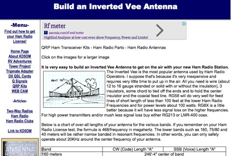 Notes on how to build an inverted V wire antenna with lenghts for all HF bands from 160 mtrs to 10 mtrs
 -
 A dual band portable inverted V antenna for 80 and 40 meters band with dimensions for other bands and several assembling instruction
 -
 The dipole shown in this document is installed in an inverted Vee configuration, with two leg elements on each side held parallel to each other by 21cm spacers. The upper leg is for 40m and the lower leg for 20m. The spacers are made of 7mm plastic garden hose support for garden sprayers cut to 21cm.
 -

-
 The program consists of tabbed pages for various antenna and transmission line calculation. You can compute the values for an inverted L network that will allow you to match the 50 ohm output of the radio, or you can compute the necessary length in the units of choice for a 5/8 wave vertical for 10 meter band.
 -
 An inverted V Dipole antenna for HF bands, working on 10 20 40 and 80 meters band. PDF Presentation
 -
 GoGreenSolar provides comprehensive solutions for **DIY solar panel systems**, catering to both homeowners and professionals seeking energy independence or reduced utility costs. Their offerings include a variety of solar kits such as Grid-Tie, Off-Grid, and Battery Backup configurations, designed to integrate seamlessly with existing utility infrastructure or provide complete autonomy in remote locations. Customers can select from Microinverter or String Inverter kits, along with essential components like **solar panels**, inverters, batteries, and racking systems, all curated from reputable brands known for efficiency and durability. The company emphasizes end-to-end support, from initial consultation and custom system design to providing easy-to-follow installation manuals. They offer financing options, including quick-approval loans with zero down payment, and a money-back guarantee if a solar permit is not approved. The platform also features a solar calculator and a questionnaire to help users determine the most suitable system for their specific energy requirements and property characteristics. GoGreenSolar aims to simplify the solar adoption process, enabling significant savings on energy bills and labor costs. Their approach focuses on empowering users to install their own systems with expert guidance, ensuring optimal performance and a secure energy future for homes and businesses.
 -
 Martek Power designs and manufactures a wide of high performance power supplies for various industries. Power supplies AC-DC, DC-AC inverters, DC-DC, EMI Filters
 -
 A trap antenna dipole covering two differen bands made reusing an old 160/80m inverted vee antenna.
 -
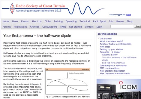 RSGB article for beginners. How to build a dipole antenna, construction tips and correct setup of inverted-ve dipole antennas
 -
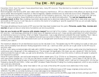 Article on radio frequency interferences, with a long list of common RFI cause, like Plasma TV, Solar panels inverters, fluorescent tube lamps.
 -
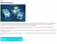 On 28.219 Mhz it puts out a whopping 3.85 watts into an inverted V dipole at about 30 ft.
 -
 Efficient Low Band Counterpoise for Restricted Circumstances Loss Avoidance Opportunities and Techniques for the Low Bands The short and linear FCP was designed to reduce ground losses from inadequate radial systems beneath inverted L and other vertical antennas.
 -
 DC filters from radius power are specifically optimized for applications with DC supply like e.g. photovoltaic inverters. Radius Power provides total power solutions, EMI filters solutions from design to manufacturing, Three Phase, Single Phase, Power Line, IEC inlet, Power entry modules Filters.
 -
 This page delves into the Inverted V antenna, a source of myths among ham radio operators. The author explores the behavior of this antenna type with a focus on a 20m half-wave dipole positioned 10m above the ground. From Pythagoras to high school math, the article simplifies the calculation of dimensions and angles for setting up an Inverted V antenna. It includes a spreadsheet for calculating hypotenuse length and angles, crucial for antenna setup. Additionally, it provides insight into the radiation pattern of a 'flat' half-wave dipole at 10m height. Useful for hams planning to optimize their antenna setup. In Norwegian.
 -
 Construction tips of a basic wire antenna, the half wave dipole. Inverted V dipoles and effects of inverted v on radiation pattern.
 -
 A 3 band dipole antenna for 40-80-160 meter bands, It's made with easily available materials and is designed for inverted V mounting. The antenna is shortened for these bands, but still manages to make contacts in 80m and 160m with stations in Canada and the USA. The construction details are provided, including the dimensions of the antenna elements and the traps. The antenna is easy to build and provides good performance in all three bands. In Italian.
 -
 On the field comparison among C-Pole antenna, an EFHW vertical antenna and an Inverter V dipole antenna. Test is done using two identical WSPRLite beacons that transmit with 200mW on the WSPR frequency and analyzing spotted results.
 -
 Discovering a solution for limited space, the inverted L HF antenna emerges as a stellar performer. Half the size of a dipole, it ensures optimal installation in restricted areas, maintaining superb transmission (TX) and reception (RX) characteristics. Spectrum Communications' multi-band version, featuring traps, proves even more space-friendly without compromising performance. A fiberglass pole offers sturdy support, while proper grounding, an RF choke, and occasional tuning contribute to a high-performing and reliable antenna system.
 -
 This 160 meter Delta Loop antenna is made of Hard drawn copper wire AWG 10, the two upper side are 148.5 foot each base wire is 240.9 foot, the feed point at 30.69 foot to one corner, feed with 450 Homs balanced line to an antenna tuner on the ground, then with 50 homs coax to the shack.
 -
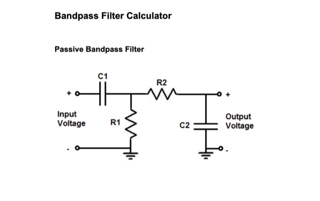 Passive Bandpass Filter online calculator and filter formulas. Active Inverting Op Amp Bandpass Filters, Active Noninverting Op Amp Bandpass Filter, just enter the Low ir High Cutoff Frequency
 -
 This antenna looks like an inverted L antenna, yet it is not, it could also be viewed as a 160m off-center fed dipole antenna, it looks more like an end-fed 1/4 wave 160 meter antenna.
 -
 This page presents an online calculator tool for determining the dimensions of various HF wire antennas operating between 1.8-30 MHz. Users input their desired resonant frequency to obtain precise measurements for four popular antenna types: standard flat-top dipole, inverted Vee, quad loop, and equilateral delta loop. The calculator provides comprehensive measurements including leg lengths, minimum heights, horizontal spreads, and feedpoint distances. Accompanying the calculator are detailed technical explanations, construction notes, and installation guidelines for each antenna type, making it a practical resource for amateur radio operators building their own antennas.
 -
 These pricey battery-powered devices are the only type of generator that can be used indoors safely. The article reviews pro and cons of power stations evaluating runtime, power delivery, power quality, ease of use, and noise.
 -
 An Inverted-L with its long leg sloping to the ground. It will still work very good, even if the horizontal wire has to be sloped diagonally to the ground, as long as you have enough horizontal space to keep it at about a 45 degree angle or more from the pole.
 -
 Operating within the low-frequency spectrum, transformers serve critical roles in antenna systems, particularly for 160m applications. The resource details the construction and performance of 1:1 transformers built on BN-73-202 cores, emphasizing their use as hybrid combiners or phase inverters for RX antenna arrays. Measurements reveal that these transformers exhibit minimal losses, around 0.12 dB at 1.8 MHz, with variations based on wire type and number of turns. The analysis includes comparative data on transformer performance, highlighting the impact of different winding techniques on frequency response. Notably, the use of coaxial cable for winding improves bandwidth while maintaining low-frequency efficiency. The resource also discusses braid breaker transformers, which minimize inter-winding capacitance, achieving low losses around 0.21 dB at 1.8 MHz. These insights are crucial for optimizing low-band antenna systems, allowing operators to make informed decisions regarding transformer design and implementation.
 -
 Opting for a visually appealing inverted L configuration, G4WIF anchors the End Fed Half Wave antenna to an old clothes line pole, seeking cost-effectiveness in their endeavor. Despite initial misconceptions about transformer components, a £7.95 investment in a T240-43 toroid and DIY mounting container resolves the issue. Reflecting on commercial alternatives, G4WIF's homemade solution proves both economical and sufficient for their amateur radio needs.
 -
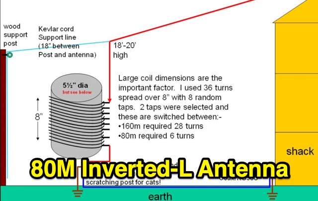 80m Inverted-L Antenna, Base-loaded for 160m antenna. This antenna is not a good DX antenna however within small garden where true DX antennas would be impossible it has performed very well.