Search results
Query: using coax as an antenna
Links: 76 | Categories: 0
-
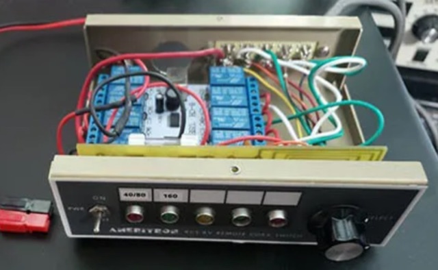 Building an automatic 8ch USB Relay switch using an existing Ameritron RCS-8V Remote Control Coax Switch and an externally mounted 5-way switch.
 -
 This document details the construction of a multi-band end-fed antenna, suitable for situations with limited space for larger antennas. The design utilizes a 1:49 to 1:60 impedance transformer to match a half-wave wire antenna fed at one end. Compared to a traditional dipole, this antenna resembles a highly unbalanced Windom antenna with one very long leg and a virtual short leg. The design eliminates the need for radials but relies on the coax cable shield for grounding. The document recommends using at least 10 meters of coax and installing a common mode filter at the entry point to the shack for improved performance.
 -
 Presents a detailed construction guide for a 9 dB, 70cm collinear antenna, utilizing readily available _RG58/U_ coaxial cable and PVC pipe for housing. The resource outlines the critical calculations for ½ wavelength sections at 444 MHz, incorporating the coaxial cable's velocity factor of 0.66, which yields a section length of 223 millimeters. It specifies the preparation and soldering of eight such half-wavelength sections, each cut to 231mm to allow for trimming, forming the core of the array. Further instructions detail the integration of a ¼ wave element (169mm #16 solid wire) at the top and a ¼ wave aluminum tube (160mm, 5/16 inch) at the bottom, crimped to the feed point's braid. The guide also addresses RF common mode current suppression by suggesting the use of _FT50-43_ toroids on the feedline. Final assembly steps cover mounting the antenna within ¾" PVC pipe using a wooden dowel, waterproofing connections, and initial SWR checks. The article also discusses scaling the design for different element counts and other VHF/UHF bands.
 -
 This article describes the construction of a simple dual-band VHF/UHF end-fed vertical dipole antenna designed for local repeater access using an Icom IC-705 radio. Built from a single piece of RG58U coaxial cable, the antenna consists of a 460mm exposed inner conductor, 450mm of intact coax, and a 9-turn choke balun wound on a 27mm former. Mounted on a 10m Spiderpole, the antenna achieves excellent SWR readings (<1.2:1 on 2m, <1.5:1 on 70cm) and provides effective coverage of local repeaters with unexpected reach into distant locations.
 -
 Online antenna calculator for a basic 3 elements yagi uda directional antenna. The described antenna design offers a front-to-back ratio of at least 20 dB, a gain exceeding 7.3 dBi, and a bandwidth (SWR < 2) of approximately 7% around the center frequency. It has an input impedance of 50 ohms when using a straight split dipole, which can be substituted with a folded dipole of the same length, increasing the impedance to 200 ohms. A matching balun is required for coaxial feeder connection, and the boom should be made of a dielectric material, like wood.
 -
 This project documents the construction and enhancement of a 30m Vertical Dipole Array (VDA) antenna inspired by Remco 7QNL article. Initial design utilized an 18m Spiderbeam pole and a 4m boom. Improvements included a lighter boom structure using fishing rods and a revised coaxial arrangement for enhanced mechanical stability.
 -
 This project details the construction of a compact, circularly polarized Quadrifilar Helix Antenna (QHA) designed for 146 MHz operation. The antenna features a 1/2λ1/2λ helical design with a 2.6:1 aspect ratio, providing 4.5 dB gain and a spheroid radiation pattern. It is ground plane independent and compatible with both vertical and horizontal polarizations, making it ideal for terrestrial and space communications. The design includes step-by-step instructions for building the antenna using readily available materials like aluminum rods, PVC pipes, and RG-58 coaxial cable. The antenna's performance has been validated through comparisons with commercial omnidirectional antennas, showing superior results.
 -
 This DIY guide details constructing a 5-element Yagi antenna for VHF frequencies. Yagi antennas offer directional signal transmission/reception compared to omnidirectional ones. The guide covers material selection (aluminum, screws, etc.), design using software or formulas, and step-by-step assembly including cutting elements, drilling holes, and attaching the coaxial cable. While calculations are provided for a 146 MHz design, adjustments are necessary for different frequencies. Safety precautions and potential result variations are emphasized.
 -
 A 10-meter half-wave vertical antenna, designed by Thomas 4L/G8BAG, offers a practical solution for hams with limited space and materials. This "flower pot" design utilizes common hardware store items such as 60mm plastic drain pipes and 75 Ohm coax cable, demonstrating that effective HF operation doesn't require specialized components. The author details the coax preparation, including stripping the outer sleeve and braid at specific measurements like **2510 mm** and 2450 mm, and integrating it into the pipe structure. The construction emphasizes simplicity and low cost, providing an accessible path to getting on the air on the 10m band, especially when a horizontal beam is not feasible. The article notes an SWR of _1.5:1_ with 75 Ohm coax, managed by an MFJ 258 for impedance matching. This temporary solution proved robust, withstanding various weather conditions and achieving contacts across continents, including W, VK, BG, G, JA, and VR2, using 100W SSB from Georgia.
 -
 The multiband tuned doublet, or center-fed Zepp, is a simple and efficient HF antenna that operates effectively across most amateur bands using a balanced parallel-wire feedline and antenna tuner. Unlike coax-fed dipoles, it tolerates impedance mismatches with minimal loss. By selecting suitable feedline and dipole lengths, one can achieve stable multi-band operation. While it doesn’t match monoband Yagis, it offers excellent performance, low cost, and broad coverage. Its radiation pattern and efficiency vary with frequency, but it remains a practical and versatile solution for HF operators.
 -
 Learn how to build a portable receiving antenna for the 160 meter band. This guide provides detailed instructions on constructing a loop antenna using a coaxial cable RG-316 with SMA connectors. The antenna weighs 1.7 kg and has dimensions of 2m in height and 1.892m in width. The wooden frame consists of four 0.945m long pieces and two 1m long pieces. Perfect for hams looking to enhance their 160m band reception during travel or portable operations.
 -
 The Dipole Bazooka Antenna for 40 meters is a popular choice among amateur radio operators. Its design allows for easy construction using materials like RG58 coaxial cable and PVC. Measurements are calculated using specific formulas; for instance, at a frequency of 7,100 MHz, the total length is approximately 19.74 meters. This antenna offers a performance range of 97% to 99%, with an impedance of 49 to 52 ohms. Additionally, it can handle up to 1 kW of power and requires no modifications for connection.
 -
 EA4EOZ details the construction and testing of 50 MHz traps, a critical component for multiband antenna designs. The project addresses the challenge of sourcing high-voltage capacitors suitable for trap applications, exploring alternatives to expensive doorknob capacitors. The author successfully fabricated a capacitor using 1.6mm double-sided FR-4 PCB material, achieving a capacitance density of **2.6 pF/cm2**. Utilizing the _VE6YP calculator_, specific L and C values of 30 pF and 0.31 uH were determined for a 2cm diameter coil. Both the FR-4 PCB trap and a coaxial cable trap, constructed from _RG-58_, were built and tuned to approximately 50 MHz using a spectrum analyzer. The coaxial cable trap demonstrated superior performance, exhibiting a notch nearly **20dB deeper** than the FR-4 version. This practical comparison provides insights into trap construction for experimental antennas, with the coaxial cable trap selected for an antenna project intended for operation at up to 100 watts.
 -
 Learn how an experienced ham radio operator rebuilt his trap dipole antenna for 30, 40, and 80 meters after a storm damage. Discover the process of upgrading to a short trap dipole for 40, 80, and 160 meters using double-wound traps made from RG-58 coax. Follow along for construction details and tips on building this unique classi.
 -
 Learn how to build a simple transmitter called the 'Easy Ten' that can be easily heard at a distance of 10 miles using a random length wire antenna thrown into a tree. This article focuses on working with frequencies in the 3.5 and 7 MHz range without the need for complex setups like coax lines or baluns. The author shares their experience of making contacts across the Pacific Ocean and the United States using just one watt of output power and simple antennas. Discover how to optimize signal output using a homemade level meter made from a DC microameter and a germanium diode.
 -
 Addresses the common challenge of constructing effective dual-band antennas for VHF/UHF operations, specifically detailing a J-pole design. It covers the theoretical underpinnings, including calculations for quarter-wavelength radiator and stub sections, accounting for velocity factor and design frequency. The resource provides practical construction guidance using readily available materials like TV twin lead and coaxial cable, culminating in an antenna with a total length of approximately 52 inches. Performance metrics are presented, showing a measured SWR of 1.7:1 or better across most of the 2-meter band and less than 2:1 across the 70-cm band. These SWR measurements, referenced to 50-ohm impedance, were taken at the transmitter end of the feed line. The article also touches upon the necessity of a balun for proper impedance matching between the balanced J-pole and unbalanced coaxial feed line, suggesting a split-core cylindrical ferrite for this purpose.
 -
 The article explains how to adapt the YAESU FT817 transceiver so that it can be used to control Kuhne electronic transverters by transmitting at +12V via the coaxial wire. Different FT817 versions imply that some of the modification proposals that have been made so far don't apply to everyone. This tutorial provides a workaround that works with all FT817 models. It makes use of the external ACC socket, connecting an interior tiny circuit board to two thin wires. Follow ON7WP's instructions for using the rear antenna socket.
 -
 This document provides comprehensive guidance on modeling and constructing multiband dipole antennas using traps. It addresses common segmentation issues in EZNEC modeling software, recommends optimal segment lengths for trap models, and compares trapped dipoles with paralleled multiband dipoles. While trap dipoles are significantly shorter, they exhibit lower gain and narrower bandwidth. Detailed instructions for building weatherproof coaxial traps include material lists, construction steps, and tuning methods. The guide notes that properly constructed coaxial traps introduce only minimal signal loss (0.6 dB) while offering practical multiband performance in a compact design.
 -
 The resource details the construction of a J-pole vertical antenna specifically engineered for motorcycle mounting, addressing the common issue of interference with top cases. It outlines the fabrication process, beginning with an aluminum angle bracket for secure attachment to the lateral support, followed by the creation of the antenna's base from an 8mm threaded rod bent into a U-shape, approximately **40mm** wide. The article specifies the precise method for coaxial cable connections using eyelets and 3mm screws, ensuring robust contact. Further construction steps involve fitting a 10mm aluminum tube onto the threaded rod, with a screw securing the radiating element and establishing core contact. The design prioritizes mechanical stability against vehicle vibrations over fine-tuning SWR with sliding collars. Initial testing yielded a _SWR_ of **1.2** across a significant portion of the band, with improvements noted by optimizing the coaxial braid contact point near the support bracket. The document provides practical insights into material selection and assembly, emphasizing durability for mobile operation. It concludes with aesthetic options, allowing the builder to paint the antenna or retain its natural aluminum finish, making it a functional and adaptable solution for UHF motorcycle communications.
 -
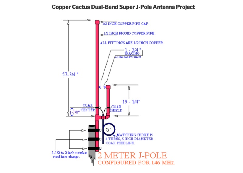 Details the construction of a Copper Cactus Dual-Band Super J-Pole Antenna, providing specific measurements for 1/2-inch copper tubing sections, including a 57-1/2-inch long section and a 19-inch short section, along with a 42-inch piece of 3/16-inch or 1/4-inch soft copper tubing for the matching stub. It covers soldering techniques for copper fittings, drilling an SO-239 panel mount coaxial fitting, and securing feed point connections with stainless steel adjustable band clamps. The resource specifies materials such as Schedule M 1/2-inch copper tubing, various copper fittings, a hardwood dowel or Fiberglas rod for insulation, and #14 stranded copper wire for the feed point. The guide simplifies the J-pole feed point by using an SO-239 fitting with an elongated mounting hole and band clamps, noting an optimal feed point distance of approximately 3 inches above the crossbar for proper impedance matching. It recommends a 4-turn coax choke, 5 inches in diameter, placed within 3 to 4 inches of the feed point for 2-meter operation to mitigate RF on the feedline. The project emphasizes weather sealing with silicon or butyl rubber compound and clear lacquer for durability and appearance.
 -
 The tri-band trapped delta loop antenna design operates on 80 meters (3.5–4 MHz), 40 meters (7–7.3 MHz), and 30 meters (10.1–10.15 MHz) using a single triangular wire loop. This configuration eliminates the need for an external antenna tuner or band-switching relays. The antenna's physical perimeter, approximately 270 feet, establishes 80M as the fundamental band, with specific trap placements enabling resonance on 40M and 30M. Trap design and placement are critical, with 30M traps positioned inboard of 40M traps within the horizontal element. Each slant leg measures approximately 80 feet. The resource references foundational information from the _ARRL Antenna Handbook_ and _ON4UN’s Low Band DXing_ regarding full-wave loop behavior and feedpoint impedances. The project aims to provide multi-band HF operation from a single, fixed antenna structure.
 -
 W1JR-style common mode chokes are versatile tools for antenna experimentation. Three variants were constructed using RK4 ferrite cores and RG303 Teflon coax, differing only in output terminals: banana connectors for dipoles, N-connectors for antennas with existing terminals, and bolts with washers for vertical antennas. Materials included junction boxes, terminals, and small hardware. Assembly involves maximizing windings on the core, securing with ties, and gluing components. Improvements included switching to multi-stranded wire for durability. These chokes provide efficient, customizable solutions for various antenna setups.
 -
 This article demonstrates how to convert an existing tower into a dual-band vertical antenna for 80- and 160-meter DX operation. Using EZNEC modeling and practical design principles, the authors achieved a low-profile, efficient setup with a single coax feed line, no moving parts, and optimal radiation patterns. The system integrates an 80-meter vertical wire and a 160-meter shunt-fed gamma match for simultaneous operation. Detailed construction insights, including feed system and capacitor configurations, offer a reliable, full-legal-power solution.
 -
 This project describes a high-performance EME antenna array consisting of two home-designed 9-element Yagis, each about 2.5 wavelengths long, combined into a 25-ohm system and matched to 100 ohms using 9/4λ sections of 50-ohm coax. The array supports rotatable polarity from 0° to 180°, allowing both horizontal and vertical polarization to optimize moonbounce performance under varying conditions. Despite operating for years without a balun—something another designer called “disastrousâ€â€”the system has delivered strong results, including copying very weak DX such as VK3KH at about -25 dB with only 120 W (around 2 kW ERP). The builder continues to refine the mechanics, having installed new gear motors and an upgraded follow-up control system in 2011.
 -
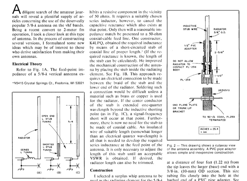 A 5/8-wavelength vertical antenna for 2-meter FM operation is detailed, focusing on eliminating loading coils by utilizing a series inductor to cancel capacitive reactance at the feed point, thereby presenting a 50-ohm impedance match. The design illustrates three basic configurations, including a method employing a short-circuited coaxial stub for inductance, as implemented by K4LPQ. An alternative design is presented where the center conductor of the stub is extended one-quarter wavelength, creating a signal-frequency short and allowing for an insulated wire stub to develop the required series inductance. The article provides electrical theory and mechanical considerations for building the antenna, emphasizing the adjustment of stub length for proper impedance matching. This technical documentation is intended for amateur radio operators interested in homebrewing VHF antennas, offering practical insights into impedance matching techniques for vertical radiators.
 -
 The 4m Slim Jim antenna project provides a construction guide for a low-cost, high-performance aerial designed specifically for the 70 MHz FM band. This design achieves a 1:1 SWR across the 4m FM band with straightforward adjustment of the feed point, utilizing RG-58 coax. Its low angle of radiation contributes to effective signal propagation. Construction involves using plastic knitting needles as spreaders and a telescopic fishing pole for support, with components secured using two-part epoxy. Annealed bare single-core copper wire forms the radiating element. The setup process includes raising the antenna at least 3 meters above ground for tuning, adjusting the RG-58 feed point for optimal SWR, and then soldering connections. Waterproofing is achieved with yacht varnish. The design emphasizes low wind resistance for durability, making it suitable for exposed outdoor installations. A PDF construction diagram is available to supplement the written instructions.