Search results
Query: transformer
Links: 115 | Categories: 2
-
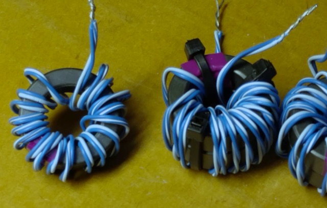 Chokes and isolation transformers are essential for receiving antennas to mitigate common mode current, which induces noise and interferes with signal quality. Common mode chokes, formed by winding feedline through ferrite cores, block unwanted current effectively. Proper selection of core material and winding turns ensures resonance near the operating frequency, reducing interference. Isolation transformers further minimize interference, crucial for multi-transmitter stations.
 -
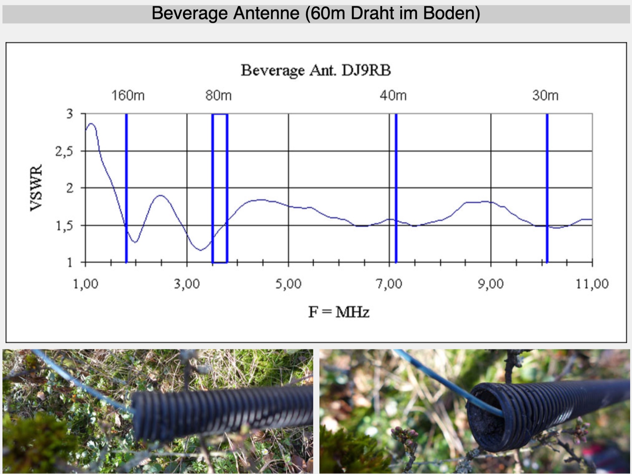 This page provides information about building a Beverage antenna for hams. The article discusses using a 60m wire on the ground to create an effective antenna for amateur radio operators. Learn how to set up and optimize this type of antenna for better reception and communication. This describes a low-noise receiving Beverage antenna setup for low bands, using a N30 cup core transformer for 1:4 impedance matching (likely 50:200 Ohm), RG-58 feedline with heavy common-mode choking, and conduit for wire burial.
 -
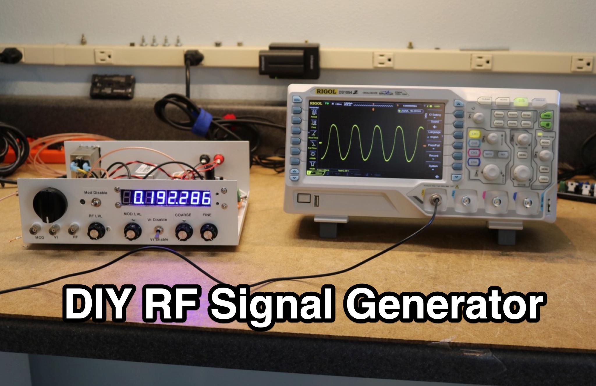 Learn how to build your own RF signal generator for aligning radios by following the modifications made to the circuit of an existing project. Explore the use of a common cathode varactor diode and a single center-tapped 24 VAC transformer to simplify the design. Discover alternative components like the MACOM 4ST079CK-287T varactor diode, which offers cost-effective solutions compared to unobtainable options. Find inspiration in modifying existing projects and gaining practical knowledge in electronics. Purchase the Nuts and Volts magazine for detailed schematics and a deeper understanding of RF signal generators.
 -
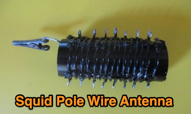 The author explores enhancing the performance of a 7-meter fiberglass squid pole wire antenna for amateur radio. The wire, resonant at 10MHz, poses impedance challenges on various bands. Experimenting with direct coax feed and UN-UN transformers, the LDG Z11-Pro2 auto-tuner is found effective but may show deceptive SWR readings. The author employs adjustable UN-UN ratios and introduces a custom "porcupine" coil to optimize the antenna's efficiency.
 -
 WB5NHL describes setting up a 160-meter antenna on a small suburban lot, where standard options like Beverage antennas and 1/4 wavelength verticals require extensive space and ground systems. Instead, Guy Olinger's Folded Counterpoise (FCP) provides a solution. The FCP minimizes ground losses by using a folded wire design, allowing effective antenna placement in limited space. The FCP, fed with an isolation transformer, enabled WB5NHL's first 160-meter antenna installation, offering improved performance despite space constraints.
 -
 Illustrates the construction of a mini ununtenna, focusing on practical design elements and component specifications for amateur radio operators. The guide covers the winding of the unun transformer, selection of appropriate ferrite core material, and integration of the radiating element. It specifies wire gauges, core dimensions, and connection points, providing a clear pathway for replication by hams. Compares the ununtenna's performance characteristics against other common wire antennas, highlighting its compact footprint and broadband capabilities. It discusses impedance matching considerations and offers insights into optimizing the antenna for various HF bands, making it suitable for portable operations or limited space installations.
 -
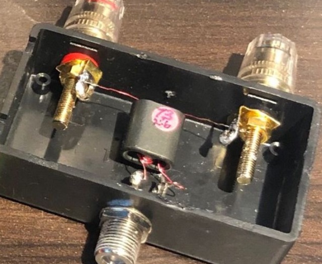 Building some proper matching transformer for loop on ground and Beverage antennas
 -
 The article by Guy Olinger, K2AV, published in the May/June 2012 National Contest Journal, introduces the Folded Counterpoise (FCP), a compact 516-foot single-wire counterpoise elevated at 8 feet, designed for 160-meter operations on small lots like 100x150-foot backyards. Originating from efforts to revive Top Band for W0UCE on a postage-stamp property, the FCP uses strategic folds to cancel ground fields within 33 feet of center, minimizing losses to 0.13-0.53 dB—outperforming sparse or on-ground radials by up to 15 dB in poor soil—while mimicking opposed radials for efficient feedpoint impedance. Paired with a critical 1:1 or 4:1 isolation transformer (e.g., trifilar on T300-2 toroid) to block common-mode currents on coax feeds, it delivers proven results: K2AV's #8 North America low-power contest score, 7+ dB gains at W4KAZ and K5AF, and over 10,000 global web hits for DIY instructions using bare 12 AWG wire and weatherproof enclosures. Ideal for acreage-challenged hams, the FCP also excels on 80 meters with scaled dimensions, offering a low-loss alternative where full radials are impractical
 -
 Demonstrates the construction of an active loop converter specifically designed for the Low Frequency (LF) bands, addressing common localized noise interference in LF reception. The design integrates a sharply tuned circuit and a tuned loop antenna, utilizing the loop as the sole tuned inductive element. By applying positive feedback, the converter significantly increases the loop's effective Q, achieving factors between 1000 and 2000, which sharpens tuning and reduces noise. The circuit employs an _NE602_ mixer stage, feeding its output to an HF receiver, with a crystal-locked local oscillator at 4 MHz. A 20-turn, 0.8-meter square loop antenna with 500 uH inductance is detailed, connected via 2 meters of figure 8 flex cable. The converter offers three selectable frequency bands: 195-490 kHz, 150-220 kHz (including the New Zealand amateur band), and 128-160 kHz (covering the European amateur band). Performance measurements indicate an effective 3dB bandwidth of approximately 100 to 200 hertz at 200 kHz. The article provides insights into component selection, including an _LF353_ op-amp and a trifilar wound transformer on a ferrite core. Sensitivity figures are presented, showing 7.5 uV of converted output per 1 uV/meter signal strength into a 50-ohm load, or 37.5 uV into an _FRG7_ receiver, highlighting its capability to extract weak signals from noise.
 -
 Designing a collapsible 6-meter beam antenna involves careful consideration of element geometry and feedline matching, as demonstrated by VE3SMA's project. The construction draws inspiration from foldable dipole concepts and established wire beam designs like the Penn. State 40m beam and the DJ4SA Spiderbeam. Utilizing **4NEC2 modeling**, the author optimized element lengths for gain and bandwidth, observing the impact of end loops on resonant frequency and the need for compensation. Feeding the approximately 25-ohm balanced antenna with 50-ohm unbalanced cable required a specialized network. This setup incorporates a choke **balun** and a matching section built from two series quarter-wave transformers using readily available 75-ohm cable. On-the-air results validate the design, including a successful 1st double hop Es QSO with 10 Watts and satisfactory performance in the CW WW VHF Contest from FN05, where 41 grids were worked with 100 Watts, showing improved performance over a simple dipole.
 -
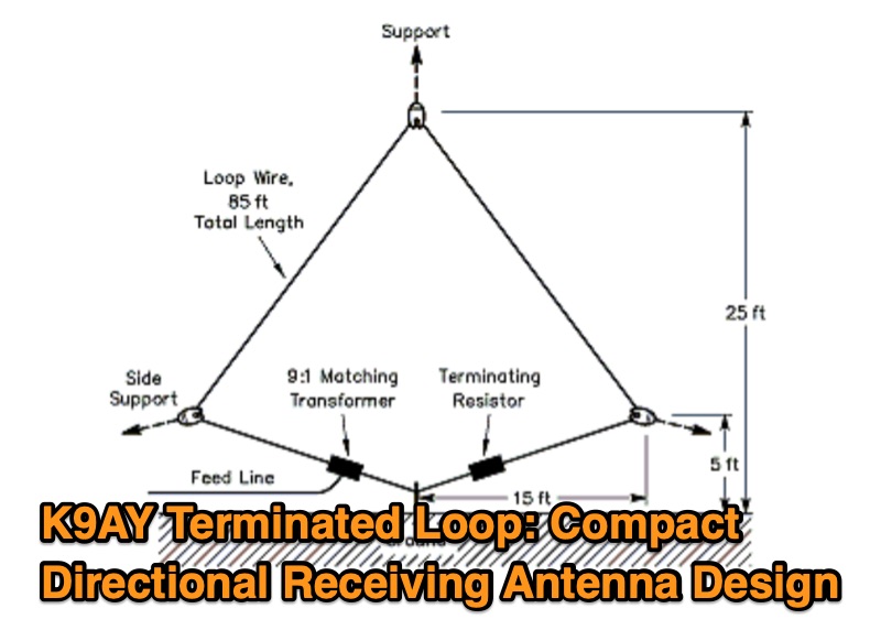 This resource presents the design and characteristics of the K9AY Terminated Loop, a compact directional receiving antenna system. The document details the antenna's physical and electrical configuration, consisting of a wire loop, a 9:1 impedance-matching transformer, and a terminating resistor. It describes how the antenna achieves directionality, favoring signals from the feed point end and rejecting signals from the terminating resistor end by several S units. The system is designed for low-band operation, specifically mentioning its application for improving reception on bands where space is a constraint. A four-direction system, utilizing two loops oriented at right angles with a relay-controlled switching system, is discussed. The resource includes a comparison of the K9AY loop's footprint to that of an equivalent EWE array, indicating the K9AY system requires approximately 1/7 the area while maintaining similar directional patterns. The design prioritizes signal collection sufficient for use with modest preamps, such as those integrated into HF transceivers. The article was originally published in QST in 1997.
 -
 Details the construction and performance of a phase-controlled receiving array, specifically a **MicroSWA** variant, optimized for QRP low band fox hunting on 40M and 80M. The resource documents the author's iterative design process, addressing significant regional noise challenges encountered during 0100-0230 UTC fox hunt periods. Initial experiments involved a director wire on a 40M vertical, yielding limited improvement, prompting a shift towards advanced null-steering techniques. The project leverages concepts from Victor Misek’s "The Beverage Antenna Handbook" and Dallas Lankford’s extensive work on phased receiving antennas for urban lots. A key modification involved integrating a new passive phase control box and a push-pull **Norton common base preamp** using 2N5109 transistors, designed for high third-order intercept performance to maintain weak signal integrity amidst strong adjacent signals. The system incorporates Faraday-shielded transformers with RG174 primaries on -75 ferrite cores, housed in ABS plastic pipe. Performance tests confirmed the MicroSWA's ability to produce deep, steerable nulls, achieving approximately 30 dB noise reduction on 160M, 80M, and 40M. This enabled detection of QRP signals undetectable on conventional transmit antennas. The final unit includes front panel controls, a 10-11 dB preamp, and a robust power conditioner, demonstrating effective noise mitigation for challenging low band QRP operations.
 -
 This comprehensive article dispels common misconceptions about Standing Wave Ratio (SWR) in amateur radio. The author explains that SWR is not an antenna property but a measure of the entire antenna system, representing the mismatch between transmission line and load impedance. Contrary to popular belief, modest SWR values (under 3:1) typically cause minimal power loss in HF applications. The article demonstrates mathematically why obsession with achieving 1:1 SWR is often unnecessary, explains when SWR matters more (QRO, QRP, VHF/UHF), and explores effective matching techniques including proper ATU placement and quarter-wavelength transformers.
 -
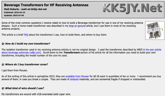 This FAQ covers building and buying transformers for loop-on-ground and Beverage antennas. Building one uses ferrite cores and thin wire. Buying is an option, with the DX Engineering BFS-1 being recommended. These transformers isolate the antenna from the cable to prevent unwanted signal pickup.
 -
 This page by Arctic Peak provides a detailed explanation on how to use quarter-wave transmission lines as impedance transformers in ham radio antenna work. It explains how to match impedance values by connecting them with a λ/4 transmission line. The page also offers guidance on constructing your own transmission lines with specific impedance requirements, along with a calculator to determine the quarter wave length based on velocity factor and frequency. Useful for hams looking to optimize antenna performance and match transmission line impedance effectively.