Search results
Query: 5 watt
Links: 220 | Categories: 4
-
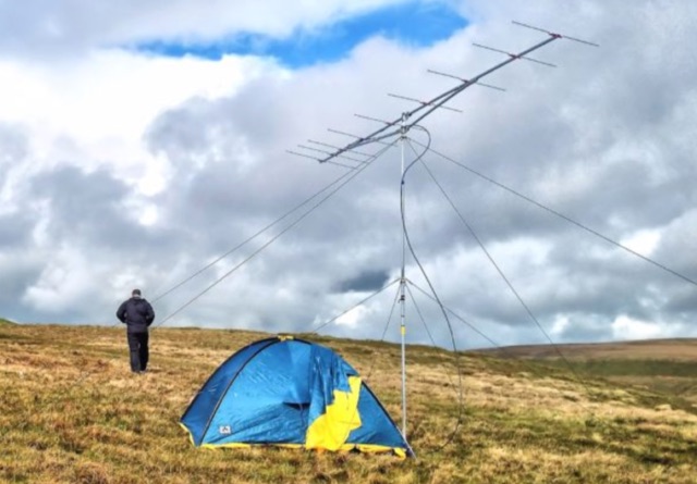 QRP is a way of operating that involves using low power transmitters, that are no more than 5 Watts for Morse or data modes, or 10 Watts pep for voice. Introduction to QRP operations
 -
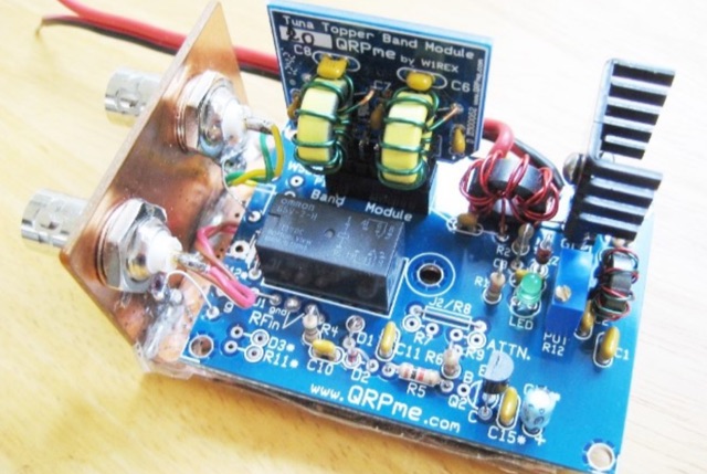 TX Topper 5 Watt plus Amplifier with Adjustable Gate Bias
 -
 The 1/4 wavelength vertical antenna project, initially designed for 20 meters, has evolved into a versatile portable solution covering 10 through 60 meters. K0BXB details its construction, emphasizing a bottom-loaded design with a tapped loading coil and four 10-foot counterpoise wires. The author shares personal experiences and field results, including **18 QSOs** during a park activation on 17m and 30m with 10 watts, and a **2,435-mile** contact with a contest station in Bonaire on 20m using 5 watts. Comparisons are drawn to commercial offerings like the _Wolf River Coils TIA_ and _QRPGuys Triband Vertical_, highlighting the DIY antenna's small footprint, light weight, and ease of tuning for POTA activations. The resource includes insights into using test equipment such as the _NanoVNA_ for SWR optimization and discusses various radiator lengths, from 17-foot wire to a 102-inch whip, demonstrating adaptability for different portable setups. Construction tips cover coil winding, tap placement, and connecting feedlines and radials using common components.
 -
 Learn how to build a simple transmitter called the 'Easy Ten' that can be easily heard at a distance of 10 miles using a random length wire antenna thrown into a tree. This article focuses on working with frequencies in the 3.5 and 7 MHz range without the need for complex setups like coax lines or baluns. The author shares their experience of making contacts across the Pacific Ocean and the United States using just one watt of output power and simple antennas. Discover how to optimize signal output using a homemade level meter made from a DC microameter and a germanium diode.
 -
 Demonstrates the construction of an **ATU-100 (N7DDC)** automatic antenna tuner, detailing the assembly process from component arrival to final enclosure. The resource covers winding the tandem match transformer, connecting the OLED display, and integrating optional control buttons. Specific attention is given to modifying the EEPROM settings for **QRP operation**, reducing the minimum tuning power to 1 Watt, and addressing potential RF interference with CPU by adding capacitors to button connections. The build log includes practical tips such as adapting RG58 coaxial cable strands for PCB mounting and utilizing a repurposed Macbook Pro cover for the custom enclosure. The author references external GitHub pages for comprehensive information, R0AEK's resources for additional details, and a video by MW0SAW for EEPROM configuration across different ATU-100 variants. Future plans involve field testing the completed tuner during SOTA or other portable activations.
 -
 The DIY Power Meter project utilizes the _INA226_ high-side power monitoring chip, paired with an ATtiny85 microcontroller, to measure voltage, current, and power, displaying the results on a 128x32 OLED screen. The INA226 communicates via an I2C interface and is programmed with a calibration factor based on the shunt resistance and current register LSB. The project is designed to handle a maximum current of 500mA using a 0.16ohm shunt resistor, which can be adjusted to a 0.2ohm resistor, reducing the full-scale current range to 409mA with a resolution of **12.5uA**. The shunt resistor dissipates only 33mW at maximum current, making 1/4 watt resistors suitable for the setup. The PowerMeter.ino sketch configures the shunt resistance and maximum design current, automatically calculating the calibration factor. The project can be prototyped on a breadboard using an Arduino Uno, employing the Wire library for INA226 and OLED communication, and the u8g2lib library for the OLED display. For the ATtiny85 version, the Adafruit-TinyWireM and Tiny4kOLED libraries are used. The power meter is independently powered by a 3V CR2032 cell, with power switching options including manual switches or DC switched jacks. The low-side n-channel MOSFET switch configuration is tested but introduces voltage drop issues, making manual switching a more reliable option until a suitable DC switched jack is found. DXZone Technical Profile: INA226 | ATtiny85 | OLED Display | Power Meter
 -
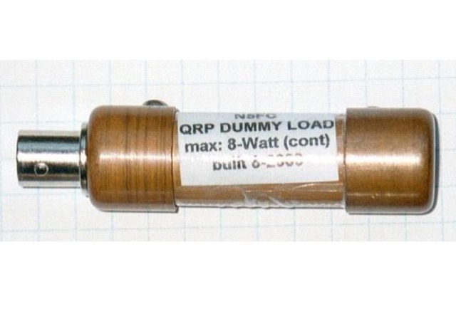 This is another variation on the parallel resistor, dummy load. It is perfect for QRP HF operation of 5-watts or less average power, and should be adequate for continuous operation at that level. It's light and compact, about 2-1/2 in length overall.
 -
 Demonstrates practical **rules of thumb** for selecting and utilizing ferrites and coils in amateur radio projects, particularly for RF applications up to 30 MHz. It addresses common challenges like determining appropriate ferrite grades and estimating L/C values without precise specifications. The resource details the author's experience with readily available grey ferrites, noting their suitability for HF work, and provides guidance on constructing **baluns** and RF chokes, balancing inductance for lower frequencies against inter-wire capacitance for higher frequencies. It also outlines a method for estimating power handling based on ferrite weight, suggesting a 1-gram ferrite can manage over 2 Watts, and offers a technique for evaluating unknown ferrites by winding 10 turns and measuring resonance with a 1 nF capacitor. This approach emphasizes a hands-on, iterative method for balun winding and adjustment, allowing operators to quickly approximate component values. The article compares the characteristics of ferrite-cored coils with air-cored coils, highlighting the reduced pickup and radiation of ferrite designs. It refines the air-coil estimation method for frequencies between 2.5 MHz and 10 MHz and provides a scaling factor for frequencies outside this range, aiming to get operators into the correct general area for their designs. The author's standardized ferrite choice (RND Components 165-00182) is presented as a practical example for reproducible projects.
 -
 The _MFJ-915_ RF Isolator, rated for 1.8-30 MHz and 1500W PEP, exemplifies the product range available from The Ham Shop. The inventory includes various antenna support ropes, such as 3/16" _Dacron Polyester Rope_ in lengths from 100 to 1500 feet, alongside a selection of cables for _SignaLink USB_ sound card interfaces. Specific SignaLink cables are offered for radios like the Yaesu FT-847 (SLCAB847), Yaesu HTs (SLCABVXY), and the Elecraft K3 (SLCABHTY). Additionally, the shop provides modular jumper cables and modules, including the SLMOD8RY for Kenwood/Alinco 8-pin round mic jacks and the SLMOD8RI for Icom 8-pin round mic jacks. The product line supports diverse station configurations, encompassing antennas, coax, baluns, dummy loads, duplexers, insulators, microphones, power supplies, SWR meters, and watt meters.
 -
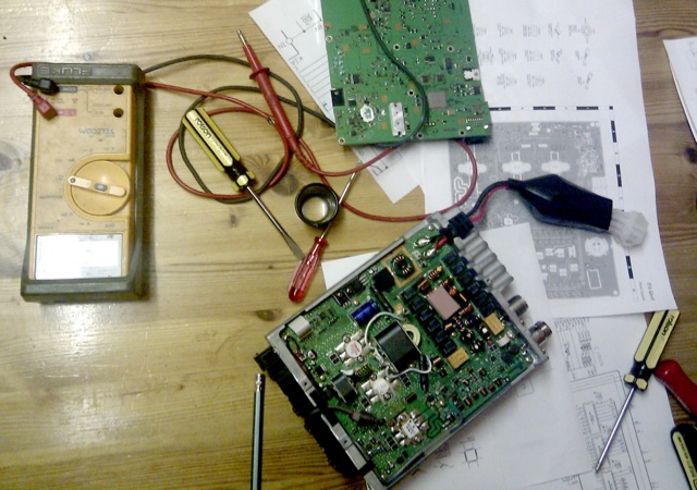 After owning the second-hand radio for a few months, it developed a sense wire failure, limiting output to 20 watts. Yaesu support advised the owner, an Electrical Engineer, to investigate. The issue was traced to a blown digital transistor, Q1032. Yaesu provided free replacements, revealing intricate internal components during the repair.
 -
 "The QRP Adventures of VE3FI" is a captivating blog that chronicles the amateur radio experiences of Bill, VE3FI, over two decades. Holding Canadian Basic, 5-word CW, and Advanced licenses, Bill's main interests include DXing and QRP operations. The blog offers detailed accounts of his portable activations, such as a recent outing in March 2025, where he achieved impressive DX contacts on the 10-meter band using just 8 watts and a Hamstick antenna. Bill's engaging storytelling and practical insights make this blog a valuable resource for both seasoned and aspiring amateur radio enthusiasts.
 -
 The Olivia digital mode, a **Multi-Frequency Shift Keying (MFSK)** radioteletype protocol, is specifically engineered for robust communication under difficult propagation conditions on shortwave radio bands from 3 MHz to 30 MHz. Developed by Pawel Jalocha in 2003, Olivia signals can be decoded even when the noise amplitude exceeds the digital signal by over ten times, making it highly effective for transmitting ASCII characters across noisy channels with significant fading and propagation phasing. Early on-the-air tests by Fred OH/DK4ZC and Les VK2DSG on the Europe-Australia 20-meter path demonstrated intercontinental contacts with as little as one-watt RF power under favorable conditions. Common Olivia modes are designated as X/Y, where X represents the number of tones and Y is the bandwidth in Hertz, with examples including 8/250, 16/500, and 32/1000. The resource clarifies that Olivia, unlike some other digital modes, produces a constant envelope, allowing RF power amplifiers to achieve greater conversion efficiencies and making it less prone to non-linearity. Operators are advised that **Automatic Level Control (ALC)** can be set higher than no meter movement for MFSK modulation, as long as it's not driven past its high limit, contrary to common misinformation about other digital modes. The Olivia community encourages voluntary channelization on suggested calling frequencies, such as 14.0725 MHz for 8/250, to facilitate initial contacts, especially for signals below the noise floor. The Olivia Digital DXers Club provides links to Groups.io, Facebook, and Discord for community engagement and offers details on QSO parties.
 -
 Twenty 1-watt carbon film resistors are configured in parallel to construct a 50-ohm **dummy load** for amateur radio applications. The design incorporates a heatsink for thermal dissipation and an **SO-239 connector** for RF input, making it suitable for QRP operations. This budget-friendly project details component selection, soldering techniques, and mounting procedures, achieving a continuous power rating of 10 watts and intermittent handling of up to 100 watts across HF and VHF frequency ranges. The resource provides a step-by-step guide for assembly. This construction offers an economical solution for essential shack tasks such as antenna tuning, transmitter testing, and SWR meter calibration without radiating an RF signal. The utilization of readily available components significantly reduces the overall build cost compared to commercial alternatives, providing radio amateurs with a functional and reliable test accessory. While specific VSWR measurements are not provided, the design prioritizes practical utility for low-power transceiver diagnostics and general RF experimentation.
 -
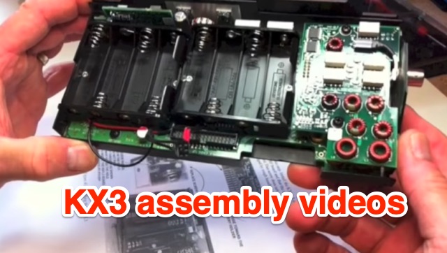 Presents a four-part video series documenting the assembly of the Elecraft KX3 QRP transceiver, offering insights into the construction process. The author, VE9KK, shares practical tips and addresses challenges encountered during his own build, providing guidance to help other builders achieve a smoother experience. The videos, while not a step-by-step instructional guide, showcase completed assembly stages and discuss lessons learned. This approach allows builders to anticipate potential pitfalls and apply proven solutions, drawing from the author's direct experience with the _KX3_ kit. Specific attention is given to areas where builders often face difficulties, ensuring that critical details are covered to facilitate successful completion of the transceiver, which is renowned for its **10-watt** output and versatile operating modes.
 -
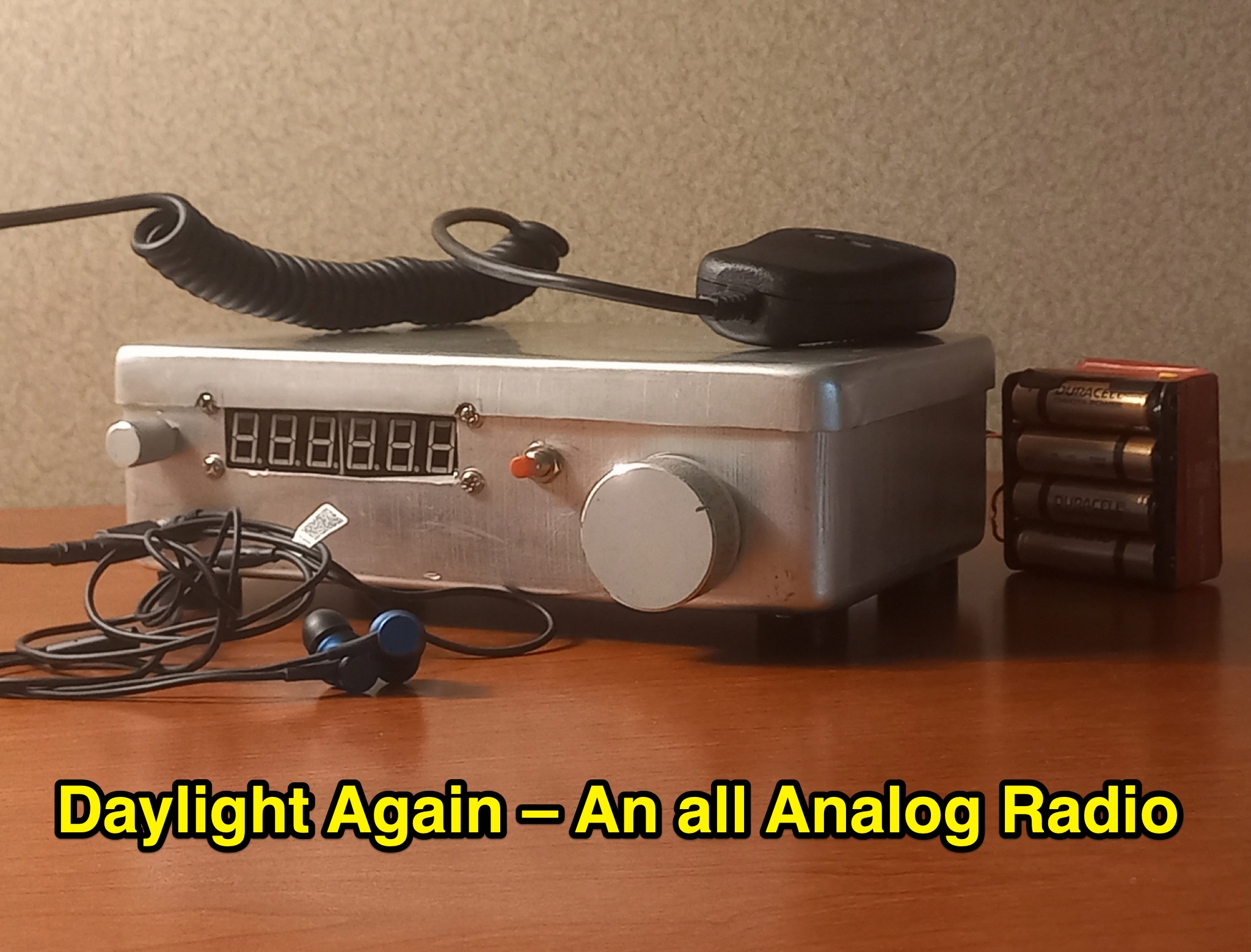 This article discusses a high performance, 7MHz, 5 watt SSB rig, the Daylight Radio, an all-analog radio design from the 1980s that includes a full circuit diagram, IMD NR60 calculations, QER crystal filter, bandpass filter, receiver portion, and more. The author explores the design, components, and functionality of this analog radio for hams interested in vintage or homebrew radio projects.
 -
 The article details how to eliminate Radio Frequency Interference (RFI) from the Behringer HA400 headphone amplifier when used in ham radio setups. While the HA400 is praised for its quality and affordability, it was not designed for RF environments, causing distortion when used with a 500-watt radio station. Initial attempts using clamp-on ferrites on the headphone and power cables only partially resolved the issue. Upon opening the unit, the author discovered the circuit lacked RF bypassing components. The solution involved installing 0.1μF (104) capacitors at key points in the circuit: the power supply input, audio circuits, and op amp inputs. This modification, combined with the external ferrites, completely eliminated the RFI problem, making the unit suitable for ham radio operations.
 -
 The page features a spreadsheet that calculates power in watt and dBm based on voltage and impedance, power in dBm with a given power and impedance, voltage in millivolts with a given power and impedance, and more. It also converts between millivolt, microvolt, volt, watt, and milliwatt. Useful for hams looking to accurately calculate power and voltage values for radio equipment. Last updated in December 2014.
 -
 An Arduino-based interface provides a remote tuner call command for Icom **IC7700** and **IC7800** transceivers, addressing the lack of a built-in function for external tuners such as the MFJ 998RT. This setup initiates a low-power transmit signal, typically 15 watts, allowing the remote autotuner to perform its matching sequence. The article details the required CI-V line communication and modifications to existing Arduino code, specifically referencing contributions from Jean-Jacques ON7EQ for improved Icom interrogation routines. The system involves a sequence of steps: storing the transceiver's current mode and power, disabling the internal autotuner, activating a control relay to interrupt the amplifier line, switching to RTTY mode at low power, and initiating transmit. The transmit duration is manually controlled by the operator, observing the SWR meter until a low SWR is achieved, then a second button press stops the transmission. A built-in 4-second transmit limit provides a safety measure. After tuning, the routine restores the original mode and power settings, re-enables the internal autotuner, and performs a brief 2-second RTTY transmission for internal tuner adjustment. The circuit diagram includes a Panasonic form 2 relay for amp control and emphasizes critical delays in the Arduino code for stable operation at 9600 baud CI-V communication. Compatibility with logging software like DXLab, N1MM, and N3FJP is noted, with specific interrogation time settings required to avoid conflicts.
 -
 The W6PQL 23cm Beacon Project describes a **1296 MHz** beacon designed for microwave propagation studies and equipment testing, capable of 30 watts output. It utilizes a PIC 16F628A microcontroller to generate CW and FSK keying for a crystal oscillator, followed by a series of frequency doublers and triplers to reach the target frequency. The final power amplification stage employs a Mitsubishi M57762 module, providing a robust 10-watt RF output. The design emphasizes stability and reliability for continuous operation, with the microcontroller code, written in assembly, provided for customization of the beacon's callsign and message. Originally located in CM97am and aimed at 140 true, the beacon used four 4-foot Yagis stacked vertically for a total ERP of 3kW. The article includes schematics, parts lists, and construction notes to guide builders, along with antenna pattern measurements. Although the beacon itself is no longer in service as of August 2010, the detailed documentation remains a valuable reference for amateur radio operators interested in building similar **microwave** projects or understanding beacon operation.
 -
 Operating an **Echolink** gateway on the 4-meter band presents unique opportunities for extending VHF communications, as demonstrated by the EI4FMG node. Situated at Fieldstown, Monasterboice, this gateway provides coverage across a significant portion of Ireland's east coast, leveraging a Tait TM8100 radio and an EI4JR Echolink interface logic. My own experience with similar setups confirms the importance of strategic site selection for maximizing reach, particularly with a 122-meter elevation above sea level. Access to the EI4FMG gateway, identified by node 57006, requires a **CTCSS** tone of 88.5 Hz, a standard practice for managing access and minimizing interference on shared frequencies. The system transmits with 15 watts of power and utilizes a Sigma CAT70 @5MAGL antenna, a configuration well-suited for regional VHF coverage. The gateway also features an auto-ID every 8 minutes, ensuring compliance and clear station identification. Users can interact with the gateway using various DTMF commands, allowing for connections to specific nodes, random repeater/link or conference nodes, and managing disconnections. These functionalities streamline the process of linking into the broader Echolink network, enabling local VHF operators to communicate globally through the internet backbone.