Search results
Query: wave
Links: 352 | Categories: 55
This query is too generic. Please try adding an additional term to focus your research.
Categories
- Antennas > End-Fed > End Fed Half Wave Antenna
- Operating Modes > Longwave
- Antennas > Longwave
- Manufacturers > Microwave
- Shopping and Services > Microwave
- Operating Modes > Microwave
- Antennas > Microwave
- Shopping and Services > Antennas > Microwave Antenna
- Manufacturers > Antennas > VHF UHF Microwave > Microwave antennas
- Technical Reference > Mircrowave
- Software > Shortwave
- Antennas > Shortwave
- Shortwave Radio
- Manufacturers > Antennas > VHF UHF Microwave
- Technical Reference > Standing Wave Ratio
- DX Resources > Beacons > 10 GHz Beacons
- Antennas > 40M > 40 meter Loop Antennas
- Operating Modes > Aircraft scatter
- Manufacturers > Antennas
- Radio Scanning > Regional > Australia
- Shortwave Radio > BCL Resources
- DX Resources > Beacons
- Shortwave Radio > Beginner's guides
- Shortwave Radio > Broadcasters
- Manufacturers > Broadcasting Equipment
- Shortwave Radio > Clubs
- Manufacturers > Antennas > VHF UHF Microwave > Discone Antennas
- Antennas > End-Fed
- Manufacturers > Antennas > VHF UHF Microwave > Ground Plane Antennas
- Antennas > Horn
-
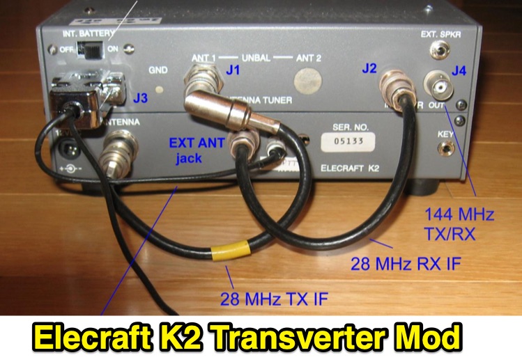 Demonstrates the conversion of an _Elecraft K2_ QRP HF transceiver to serve as a 2-meter Intermediate Frequency (IF) rig for microwave transverters, addressing the obsolescence of older _Yaesu FT-290R_ units. The project integrates a _DEMI 144-28DC_ transverter board, configured for a 28 MHz IF, and details the necessary modifications to the K2, including the installation of the K160M module for a separate receive-only antenna input and the KSB2 SSB module for voice operation. The modified K2 provides a stable 1-watt output for the 2m IF, utilizing the QRP antenna jack for transmit and the K160M input for receive, with a custom PTT control circuit. The article outlines the physical integration and electrical interfacing, including the design of an internal attenuator for the 28 MHz IF output and a control circuit for the 144 MHz interface. It also covers the construction of a medium power amplifier using an _MGA-31389 MMIC_ to boost the 2m output to 100 mW, matching the original FT-290R performance. Performance measurements for the amplifier, including output power versus input power and gain versus frequency, are presented. The project culminates in a fully integrated solution, with schematics and photos illustrating the internal wiring and external connectors. The modified K2, dubbed the "K290R," was successfully deployed in the 2017 _ARRL 10 GHz and Up Contest_ with a _Kuhne 10 GHz_ transverter, demonstrating reliable operation for CW and SSB modes.
-
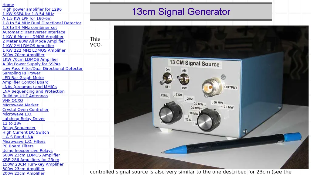 This online construction guide details the assembly of a signal generator specifically for the **13cm band** (2.4 GHz). The curriculum focuses on the integration of a Voltage Controlled Oscillator (VCO), specifically the ROS-2400, to produce a stable RF signal. The resource outlines the necessary components for frequency generation and output, including the use of a Mini-Circuits MMIC amplifier for signal conditioning. The construction protocol involves configuring the ROS-2400 VCO to operate within the 2.3 GHz to 2.45 GHz range, ensuring frequency coverage for amateur radio _microwave experimentation_. The guide specifies the output power level, approximately 70mW, directly from the MMIC stage, indicating its application as a low-power instrumentation source rather than a transmit-capable device. This project provides a practical example of constructing a dedicated test instrument for microwave frequency measurements and system alignment on the **13cm band**. DXZone Focus: Construction Guide | 13cm Signal Generator | VCO Integration | Microwave Experimentation