Search results
Query: arrow antenna
Links: 29 | Categories: 0
-
 Demonstrates the construction of a **remote antenna tuner** utilizing a standard radio-controlled (RC) servo mechanism to adjust a variable capacitor. The design focuses on enabling remote tuning for narrow-bandwidth antennas, specifically mentioning frame and packing crate antennas, from within the shack. It covers the mechanical arrangement for integrating the servo with a capacitor and provides a circuit diagram for a control unit that generates the necessary 0.5mS to 1.5mS pulse-width modulation (PWM) signals to drive the servo's 180-degree rotation. This setup was successfully tested with up to 20 watts RF power without arcing or adverse effects on the servo, though tuning was performed at 1 watt for VSWR readings. The resource highlights the use of inexpensive, readily available components, such as Futaba servos, and details critical considerations like power supply decoupling with a 47uF capacitor to prevent unintended servo movement upon power-off. The system provides a practical solution for optimizing antenna performance for specific frequencies without manual adjustment at the antenna itself.
 -
 Over 30 distinct shortwave (SW) receiver models are reviewed, offering insights into their performance, features, and user experiences. These evaluations, contributed by readers of the Usenet newsgroup **Rec.radio.shortwave**, cover a wide array of portable and tabletop radios, including popular units like the Grundig YB-400, Sony ICF-SW77, and various Realistic DX series models. Each review details aspects such as frequency range, tuning steps, SSB functionality, antenna performance, and construction quality, often comparing them to other receivers or ham transceivers like the Icom 725. For instance, the Grundig YB-400 review highlights its 144-30000 kHz AM/SSB coverage, direct keypad entry, and 40 station memories, noting its useful narrow bandwidth and tone switch for adjacent signal separation. It also discusses the **SSB mode** stability and the limitations of its 1 kHz frequency resolution for precise zero-beating. The review further details antenna performance, including the effectiveness of the built-in whip, the provided 7m reel antenna, and the potential for overload with larger outdoor antennas. Other reviews delve into specific issues, such as the Sony ICF-SW77's frequency display inaccuracies and timer malfunctions, or the Realistic DX-342's compact size and surprisingly good MW DXing capabilities despite its analog tuning. The collection provides practical, user-generated feedback on sensitivity, selectivity, audio quality, and ergonomic features, helping shortwave listeners understand the real-world performance and quirks of these receivers.
 -
 Demonstrates the construction and on-air performance of the _NB6Zep_ antenna, a modified 20-meter Extended Double Zepp design optimized for multi-band operation from 40 through 10 meters. The resource covers basic design principles, including dimensions of 66 feet horizontal and 5 feet vertical elements, and specifies open ladder line or TV twin lead for the transmission line. It details material selection for low-cost wire antenna construction, such as 18 AWG wire for the legs and ceramic or plastic insulators, along with practical tips for soldering connections and insulating against moisture. The author, NB6Z, shares insights from extensive _EZNEC_ modeling to optimize the antenna's total length for a 40-meter half-wave dipole footprint and feed line length for direct tuner connection. The article presents field results, including successful _PSK31_ contacts from Oregon to the East Coast on 40 and 30 meters with 50 watts, even at a low height of 6 feet. It provides detailed performance characteristics for each band, noting the _NB6Zep_'s highest gain (over 3 dB) and sharp, medium-angle lobes on 20 meters, which yielded strong DX reports to locations like Korea, Japan, and Argentina. For 17 and 15 meters, it describes a butterfly-like pattern with broad lobes, while 12 and 10 meters exhibit narrow, directional lobes in an "X" configuration. The author also shares personal experiences operating successfully for over a decade in an antenna-restricted environment using the NB6Zep and other stealth wire antennas.
 -
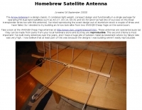
 This project details three variants of a vertical half-wave antenna design for the 4-meter (70MHz) amateur radio band. The antennas use end-feeding with a parallel-tuned circuit for impedance matching to 50-ohm coaxial cable. The first variant uses suspended flexible wire for portable use, the second employs a fiberglass rod with internal wire for permanent outdoor installation, and the third utilizes aluminum tent poles for quick mobile deployment. Despite the narrow bandwidth of the matching circuit, this suits the narrow 4m FM allocation well. The design offers an effective omnidirectional radiation pattern and can be constructed with readily available materials.
 -
 The **NW3Z** optimized wideband antenna designs, originally presented at Dayton 2001, detail Yagi configurations for the 20-meter, 15-meter, and 10-meter amateur radio bands. This resource provides access to the design files, likely containing critical parameters such as element spacing, element lengths, and boom dimensions, which are essential for replicating these directional antennas. The designs focus on achieving wide bandwidth, a desirable characteristic for contesters and DXers operating across a significant portion of each band. The content specifically references "nw3z-Antenna-DesignsDownload," indicating that the core information is available as a downloadable file, presumably in a format suitable for antenna modeling software or direct construction. Such files typically include **NEC models** or similar data, allowing for performance analysis and optimization before physical construction. The emphasis on "optimized wideband" suggests design considerations for SWR bandwidth and gain characteristics over a broader frequency range than typical narrow-band Yagis. The resource serves as a direct source for specific, proven antenna designs from a known amateur radio antenna designer, offering practical data for hams interested in building high-performance Yagi arrays for HF.
 -

-
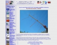 Arrow-Style VHF/UHF portable satellite antenna by VE2ZAZ
 -
 A suitable high gain 70cms antenna for SOTA operation was sought that did not have the drawbacks of a long Yagi antenna, principally a narrow beamwidth and bandwidth.
 -
 The Arrow Antenna is a design classic: it combines light weight, compact design and functionality in a single package for operating FM dual band satellites such as AO-27, UO-14, SO-41 and SO-50
 -

-
 Presents a QRP AM/CW transmitter project specifically designed for the 10-meter band, utilizing a crystal oscillator and a collector-modulated AM oscillator. The design employs a 2N2219(A) transistor in a Colpitts configuration, generating 100 to 350 mW of RF output power depending on the 9-18 Volt supply voltage and modulation depth. Frequency stability is maintained by a 28 MHz crystal, with fine-tuning possible via a Ct1 trimmer capacitor for approximately 1 kHz adjustment. The resource details the RF oscillator stage, implemented with a 2N2219 NPN transistor, emphasizing frequency stability and low power dissipation. It also covers the amplitude modulation stage, managed by a 2N2905 PNP transistor, which impresses audio information onto the carrier. Selective components (C3, C4, C7, C5) enhance voice frequencies within a +/- 5 kHz bandwidth, and modulation depth is controlled by R2 and R3. The project includes a 3-element L-type narrow bandpass filter (Ct3, L3, C10) to suppress harmonics and ensure a clean output signal. The project provides a complete schematic diagram, a comprehensive parts list including specific capacitor, resistor, and inductor values, and construction notes for the coils (L1, L2, L3). It also offers practical advice on enclosure requirements, suggesting an all-metal case or a PVC box with graphite paint for RF shielding. Operational parameters such as current draw (27mA@9V to 45mA@16V) and input impedance (50 Ohms) are specified, alongside guidance on antenna matching and the importance of a valid amateur radio license for 10-meter band operation.
 -
 Operating on the 2200m band (135.7-137.8 kHz) often presents challenges for amateur radio transceivers, which typically exhibit poor receiver performance at these very low frequencies. This project addresses the issue by providing a design for a dedicated 137 kHz antenna preamplifier, specifically tailored to improve signal reception for radios such as the _Yaesu FT-817_. The preamplifier circuit utilizes a low-noise FET input stage, crucial for minimizing self-generated noise and maximizing the signal-to-noise ratio from weak LF signals. The design includes a detailed schematic, component values, and construction notes, enabling homebrewers to build a functional unit. The goal is to achieve significant gain, making the faint signals on 2200m more discernible and improving overall band usability. Key design considerations include impedance matching to typical antenna systems and ensuring stable operation across the narrow LF segment. The circuit aims for a **low noise figure** and sufficient amplification to overcome the inherent limitations of general-purpose HF transceivers when operating below **200 kHz**.
 -
 Antenna model for a diamond loop wire antenna for the 40 meter band
 -
 The **KC0KJF** personal amateur radio page provides a collection of resources for fellow hams, particularly those interested in operations within southwest Missouri. It offers detailed listings for **Missouri repeaters** on both 2 meters and 70 centimeters, serving as a practical reference for local VHF/UHF communication. The site also includes information about the operator's station setup and antenna projects, such as a dipole and a bazooka antenna, which can offer insights into basic antenna construction and deployment. Beyond local repeater data, the page features links to the FCC Part 97 rules, essential for understanding amateur radio regulations. The operator, licensed as a Technician Class since April 16, 2001, shares his journey from Citizen's Band Radio to amateur radio, driven by a lifelong fascination with shortwave listening. This narrative provides context for the resource's focus on practical operating information and foundational regulatory knowledge. Additional content covers specific equipment like the 2-meter/70-centimeter Arrow Antenna, useful for hams considering portable or fixed station VHF/UHF setups.
 -
 The NB6Zep Antenna, an electrically shortened 80-meter end-fed wire, addresses space constraints for low-band operation by integrating two loading coils into a 37-foot wire. This design, modeled with _EZNEC_, explores configurations like the quarter-wave sloper and inverted-L, with the latter providing a more vertical radiation pattern and practical backyard deployment. The resource details specific coil construction, recommending 21 uH coils made from _BW coil stock #3026_ or similar, and outlines wire segment lengths for optimal tuning. Performance analysis indicates a radiating efficiency of approximately 27% with good ground conductivity, resulting in a signal typically 3-4 dB down compared to a full-size quarter-wave vertical. The antenna exhibits a narrow bandwidth, around 50 kHz, due to its high Q, necessitating a tuner for broader band operation. Feedpoint impedance is low, with ground resistance playing a critical role in achieving a usable SWR. The article emphasizes the importance of an effective ground rod at the feedpoint for proper operation and tuning, suggesting an antenna analyzer for precise adjustments. It confirms the antenna's suitability for DX, citing successful contacts from Oregon to the East Coast and Hawaii on a 160-meter variant, making it a viable option for urban operators seeking low-angle radiation on 80 meters.
 -
 KD8KSB realization of the CJU satellite antenna that allow similar performance to the arrow antennas.
 -
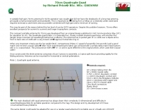
 A 70 cm yagi designed for EME + SSB narrow bandwidth version, strictly G/T breeding. This little Yagi has a high F/B, which makes it quite useful as a contest stack
 -
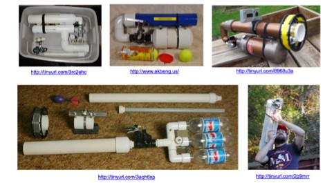 Investigates the legal framework surrounding **pneumatic antenna launchers** in Victoria, Australia, specifically their classification under the Firearms Act 1996. The author, VK3KBC, details how these devices, designed to discharge a projectile by compressed air, are defined as 'firearms' and subsequently categorized as **Category E Longarms**. This classification carries significant penalties for unregistered possession or use, with the author noting the lack of provisions for amateur radio operators to legally possess and use such devices for antenna deployment. The author shares personal experiences needing such devices for portable HF radio operations, contrasting them with previously legal slingshots and current alternatives like kites or bow and arrow. VK3KBC outlines efforts to advocate for legislative change, including submissions to the Wireless Institute of Australia (WIA) and the Victorian Department of Justice, proposing an amendment to Section 3(i) of the Firearms Act 1996 to include amateur radio field operations as an exempted use. The resource also reviews the original intent of the Category E firearm classification, suggesting that pneumatic antenna launchers may have been assigned this category in the absence of a more suitable alternative.
 -
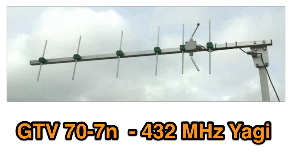
 This article is about a 4 element yagi VHF antenna designed to be easy to be assembled and suited for portable operations
 -
 The collinear antenna, or Marconi-Franklin antenna, is an omnidirectional, high-gain antenna composed of in-phase half-wave dipoles aligned vertically. By using quarter-wave transmission line segments, it maximizes gain at a low horizon angle, outperforming a half-wave dipole. Adding segments increases gain but narrows bandwidth. A popular DIY version, the CoCo antenna, uses half-wave coaxial cable segments connected by non-radiating transmission lines. Built with stable velocity factor cables, a matching quarter-wave sleeve balun, and ferrite rings for attenuation, the antenna achieves performance comparable to commercial models.
 -
 A very popular method of making a short dipoles resonate at a given frequency. This type of antenna is suitable for single band, narrow bandwidth use.
 -
 Amateur Television (ATV) operations involve transmitting and receiving live or recorded video and audio signals over amateur radio frequencies. Unlike narrow-band modes, ATV utilizes a wider bandwidth to convey video information, often requiring specialized transceivers, antennas, and signal processing equipment. This mode allows hams to share visual content, demonstrate projects, or conduct video conferences, typically on VHF, UHF, and microwave bands due to the bandwidth requirements. The SwissATV resource focuses on the technical aspects and community engagement surrounding ATV within Switzerland. It covers topics relevant to setting up ATV stations, understanding signal propagation at higher frequencies, and participating in local ATV activities. The site serves as a central point for Swiss ATV operators to exchange knowledge and coordinate transmissions, fostering the growth of this specialized amateur radio mode.
 -
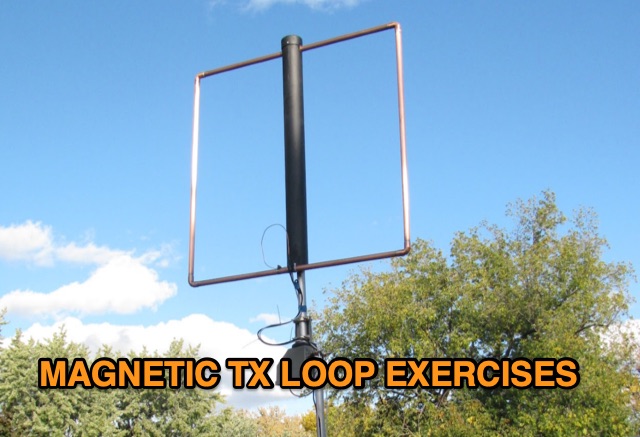 Explore two magnetic loop antenna constructions, utilizing a 6-foot and a 12-foot square loop. Accompanied by a detailed description, the 6-foot loop features a built-in stepper motor control circuit, while the 12-foot loop incorporates a separate loop controller. Efficiency, tuning ranges, and the innovative autotuning solution using a microcontroller are discussed, offering insights into overcoming the antenna's narrowband limitations.
 -
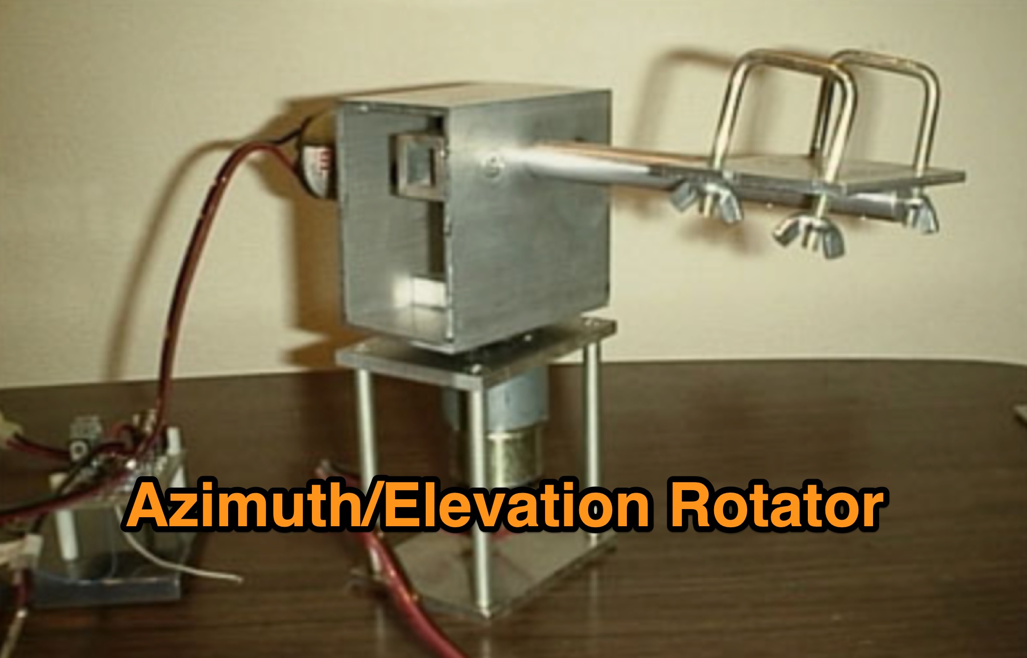 Learn how to build a simple 12vdc azimuth and elevation motor unit for the Arrow Satellite Antenna to improve your FM satellite communication experience. This DIY project involves using a camera tripod and basic materials like aluminum tube and standoffs. Get detailed instructions, including the gearhead motor product number for optimal performance. Discover where to purchase the necessary components and stay updated on alternative motor options. Enhance your ham radio operations with this homemade rotator setup, designed for easy satellite tracking and communication. Share feedback and connect with other radio enthusiasts for more tips and ideas.
 -
 Showcasing German engineering, ANjo Antennen develops and manufactures a diverse portfolio of amateur radio and commercial antenna products. Their offerings span a wide frequency range from 1.8 MHz to 3000 MHz, emphasizing electrical and mechanical precision for longevity. The company actively participates in events like FUNK.TAG Kassel, providing opportunities for direct engagement and order pickup. ANjo's product line includes high-performance **Yagi antennas** optimized for Tropo and EME, along with multi-stacked Quad antennas designed for contest operations, featuring wide horizontal and narrow vertical beamwidths. They also produce circularly polarized satellite antennas, some with switchable LHCP/RHCP, leveraging their commercial satellite antenna expertise. Beyond amateur applications, ANjo provides flexible, custom antenna solutions for commercial sectors such as BOS, EMC measurements, and telemetry. Their commitment to quality is evident in the Premium-Line antennas, which utilize **1.4301 (V2A) stainless steel** for mast clamps and connectors, ensuring durability and corrosion resistance. They also offer end-fed HF multiband wire antennas, known for their compact footprint and discreet installation.
 -
 A small magnetic loop antenna, often employed by hams facing antenna restrictions or high local RFI, offers a compact solution for HF operation. This resource details the construction of a foldable magnetic loop designed for the 40m through 17m bands, emphasizing its high-Q factor and _Faraday coupling_ for effective noise rejection and narrow-band filtering. The guide outlines material selection, advocating for copper over aluminum to maximize efficiency, and provides insights into the physics governing its operation, including impedance matching and resonance principles. Practical application of this antenna design is particularly beneficial for QRP enthusiasts and portable operators seeking a stealthy, high-performance antenna. The construction process includes specific details for a 1-meter diameter loop, a 140pF variable capacitor, and a _gamma match_ for impedance transformation. Performance comparisons suggest that while a full-size dipole might offer slightly better gain, the magnetic loop's ability to mitigate local noise often results in a superior signal-to-noise ratio, making it a viable option for challenging RF environments.
 -
 This project introduces the Loggi, a hybrid antenna merging the wide frequency coverage of log-periodic dipole arrays (LPDA) with the high gain and front-to-back ratio (F/B) of Yagi antennas. Traditional LPDAs span broad frequencies with moderate gain and low VSWR, while Yagis provide high gain and F/B over narrow bands. By analyzing high-Tau LPDA designs, it was found they could nearly match the gain of VHF/UHF Yagis while maintaining excellent patterns, F/B, and front-to-rear ratios (F/R). Optimizing specific elements for target frequencies (e.g., 144.1 MHz) led to the Loggi, which uniquely features all driven elements without passive directors or reflectors. This design effectively functions as a narrowband optimized LPDA, with front elements acting like Yagi directors and rear elements like Yagi reflectors, thus enhancing gain and directional characteristics while retaining broad frequency versatility.
 -
 This document provides comprehensive guidance on modeling and constructing multiband dipole antennas using traps. It addresses common segmentation issues in EZNEC modeling software, recommends optimal segment lengths for trap models, and compares trapped dipoles with paralleled multiband dipoles. While trap dipoles are significantly shorter, they exhibit lower gain and narrower bandwidth. Detailed instructions for building weatherproof coaxial traps include material lists, construction steps, and tuning methods. The guide notes that properly constructed coaxial traps introduce only minimal signal loss (0.6 dB) while offering practical multiband performance in a compact design.
 -
 Integrating a _Software Defined Radio_ (SDR) into an existing ham radio setup involves connecting it with a standard transceiver (TRX), power amplifier (PA), and antennas. The core component is a splitter box that facilitates the connection between the TRX and the SDR, allowing for simultaneous operation without modifying existing equipment. In receive mode, the splitter ties the antenna inputs of both the TRX and a direct conversion receiver (DC RX) together. During transmission, the DC RX input is grounded via a fast telecom relay controlled by the transceiver's -SEND signal, incorporating a 10ms delay for safety. The splitter box includes a 3.7 dB input attenuator for impedance matching and acts as a protective fuse for the DC RX input. Ground loops are mitigated using common mode balun transformers, while the DC RX input is insulated with a broadband transformer. An audio switch box complements the setup, enabling users to listen to either the main transceiver, the SDR output, or both simultaneously. This configuration ensures noise immunity and safety, with the splitter housed in a screened box made from PCB material. On-air tests, such as the CQ WW 160m CW DX Contest, demonstrate the system's effectiveness, showcasing the SDR's ability to handle crowded band conditions with superior selectivity and dynamic range. The SDR's narrow bandwidth filters and waterfall display provide significant advantages, allowing operators to detect weak signals amidst strong interference. The integration of SDR with conventional radios offers enhanced operational flexibility and performance in challenging environments.