Search results
Query: inductance capacitance
Links: 13 | Categories: 1
Categories
-
 Author evaluated a custom-built passive AM loop antenna, achieving notable DX reception including KLBJ Austin (230 miles) and WWL New Orleans (700 miles). The antenna operates solely on resonant inductive coupling, enhancing weak signal reception without external amplification. This project illustrates how fundamental RF design—calculating inductance, capacitance, and Q factor—can significantly boost performance of consumer-grade radios. Detailed construction techniques, theoretical background, and optimization strategies for effective loop antenna design are presented for amateur and experimental use.
 -
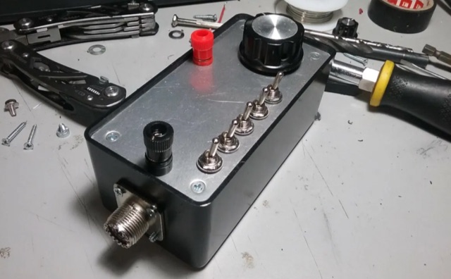
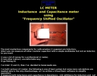 Inductance and Capacitance meter using``Frequency Shifted Oscillator
 -
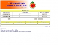 LCF online Calculator, calculate relation between Frequency Capacitance Inductance and Reactance
 -
 The QRP choke balun described utilizes a high permeability ferrite rod and RG-174 coax, aiming to present high impedance to common-mode currents across the HF spectrum. The construction involves winding as many turns of RG-174 as possible around the ferrite rod, then encapsulating the assembly with hot glue. This design prioritizes maximizing inductance to suppress unwanted shield currents, particularly in unbalanced antenna configurations. While the balun's effectiveness is subjectively reported as good, a potential design consideration involves the dielectric properties of the hot glue. This material could increase turn-to-turn capacitance, potentially reducing the balun's performance at higher HF frequencies, though this specific aspect has not been formally tested by the author, _AA5TB_. The project serves as an illustrative example of a practical, junk-box construction rather than a rigorously engineered solution. Photographs detail the evolution of the balun, from the initial winding process to its integration within a _B&W dipole center insulator_ and final camouflaged assembly.
 -
 Demonstrates the construction and measurement of a single-turn HF receiving loop antenna, built from common materials like electrical conduit and lamp cord. The resource details the physical dimensions, including a 4-meter circumference, and calculates the theoretical inductance at approximately _6.4 uH_. It outlines a method for determining resonant frequencies across the 4-17 MHz range using a _C Jig_ and a _VR-500 receiver_, coupling the loop with a ferrite ring. The article also discusses the impact of receiver coupling on the loop's Q factor, noting a degradation in sharpness due to the transformer's reflected impedance. Analyzes the observed resonant frequency patterns, highlighting an unexpected rise in the loop's effective inductance at higher frequencies, particularly above 13 MHz. While some increase is attributed to distributed capacitance, the rate of rise suggests further investigation. The experimental setup provides practical insights into the challenges of maintaining high Q in simple receiving loops and offers a comparative reference for other homebrew antenna projects, such as those by _VK2TPM_.
 -
 Determining the characteristic impedance (Z) of an unknown coaxial cable, a common challenge for many radio amateurs, can be resolved with a straightforward method. The impedance of a coaxial cable is derived from its inductance and capacitance, and importantly, these values are independent of the cable's length or the operating frequency. This means that measuring a random length of cable, such as 20 meters, provides sufficient data for calculation. The core of this technique involves an LC-meter to obtain the inductance (L) in microHenries (uH) and capacitance (C) in microFarads (uF). The impedance is then calculated using the formula Z = L/C. For instance, a measurement yielding L=1.2uH and C=450pF (0.00045 uF) results in an impedance of 51.6 Ohms, closely matching **RG-58** specifications. Similarly, a TV coaxial cable with L=1.8uH and C=320pF (0.00032 uF) calculates to 75 Ohms. While the accuracy of this method, depending on the LC-meter's tolerance, is approximately 10%, it proves sufficiently precise for practical determination of unknown coaxial cable impedance, as noted by Makis, SV1BSX, who credits Cliff, K7RR, for the formula's dissemination.
 -
 An inductance and capacitance meter, measuring range is from 0 to >0.1uF for capacitance and 0 to >10mH for inductance. A project by Phil Rice, VK3BHR
 -
 An L-Match tuner is a device that can add either inductance (L) or capacitance (C) to the antenna, bridging that gap between 5000 ohms and 50 ohms, thus matching it to the radio. The L-Match tuner is an extremely useful device that every QRP operator will want to have.
 -
 Presents Wayne Kerr Electronics, a manufacturer specializing in precision component measurement products. The company offers a range of LCR meters, impedance analyzers, and transformer test systems designed for various applications in electronics manufacturing and research. Specific product lines include the 3260B Precision Magnetics Analyzer, which measures inductance, capacitance, and resistance with high accuracy, and the 6500B series of LCR meters, capable of testing components across a broad frequency range up to 120 MHz. The 3255B and 3265B series provide solutions for transformer and inductor testing, including turns ratio, leakage inductance, and inter-winding capacitance measurements. These instruments are utilized in quality control, component characterization, and production line testing, ensuring performance and reliability in electronic circuits. Wayne Kerr's offerings support engineers and technicians in verifying component specifications.
 -
 Coil64 (Coil32) is a versatile tool for calculating single-layer inductance coils used in various electronics, such as matching circuits and amplifiers. The online calculator enables users to estimate the number of turns, winding dimensions, and select the appropriate wire type for home-brewed RF inductors. It employs Bob Weaver's equation, factoring in wire corrections, and allows for the calculation of Q-factor and self-capacitance. Coil64 is compatible across multiple platforms, including Windows, Linux, Mac-OS, and Android.
 -
 An **Arduino LC Meter** provides an accessible solution for precisely measuring inductance and capacitance values, crucial for RF circuit design, filter tuning, and troubleshooting in amateur radio applications. This project details the construction of a low-cost, accurate instrument using readily available components, making it an attractive alternative to commercial units for hams and electronics enthusiasts. The build process involves assembling a resonant circuit, integrating an Arduino microcontroller for frequency measurement, and displaying results on an LCD. Key components include an Arduino Uno, a 16x2 LCD, a 74HC14 Schmitt trigger inverter, and a few passive components. The design leverages the Arduino's processing power to calculate L and C values from resonant frequency shifts. Calibration procedures are outlined to ensure measurement accuracy, which is vital for critical RF work. The project includes schematics, a parts list, and the necessary Arduino code, enabling hams to construct a functional LC meter for their workbench.
 -
 Demonstrates practical **rules of thumb** for selecting and utilizing ferrites and coils in amateur radio projects, particularly for RF applications up to 30 MHz. It addresses common challenges like determining appropriate ferrite grades and estimating L/C values without precise specifications. The resource details the author's experience with readily available grey ferrites, noting their suitability for HF work, and provides guidance on constructing **baluns** and RF chokes, balancing inductance for lower frequencies against inter-wire capacitance for higher frequencies. It also outlines a method for estimating power handling based on ferrite weight, suggesting a 1-gram ferrite can manage over 2 Watts, and offers a technique for evaluating unknown ferrites by winding 10 turns and measuring resonance with a 1 nF capacitor. This approach emphasizes a hands-on, iterative method for balun winding and adjustment, allowing operators to quickly approximate component values. The article compares the characteristics of ferrite-cored coils with air-cored coils, highlighting the reduced pickup and radiation of ferrite designs. It refines the air-coil estimation method for frequencies between 2.5 MHz and 10 MHz and provides a scaling factor for frequencies outside this range, aiming to get operators into the correct general area for their designs. The author's standardized ferrite choice (RND Components 165-00182) is presented as a practical example for reproducible projects.
 -
 Demonstrates the design and modeling of a **160m** vertical antenna, dubbed the "WindoVert," specifically for urban amateur radio operators with limited space. The resource covers the theoretical underpinnings of antenna height and radiation patterns, using EZNEC software to analyze current distribution and 3D radiation patterns for various configurations, including a Marconi-style "T" antenna. It details the integration of existing antenna components, such as a Carolina Windom balun and line isolator, into the new vertical setup, and the practical measurement of feedpoint impedance using an antenna analyzer. The article further explores the challenges of achieving low-angle radiation on Top Band, emphasizing the critical role of radial systems and mitigating ground loss. Author VE1ZAC presents EZNEC models illustrating the impact of lumped components and discusses the practical considerations of resonant frequency adjustment and impedance matching for **QRP** operation. The text details the calculation of required loading coil inductance and capacitance, and shares field results, including successful DX contacts on 160m and unexpected excellent performance on 30m.