Search results
Query: j-pole antenna plan
Links: 22 | Categories: 1
Categories
-
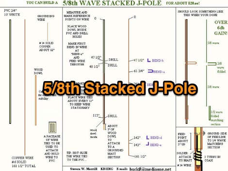
-
 Sixty-four years of operating experience inform Glynn E. "Buck" Rogers Sr., K4ABT's, insights into the J-Pole antenna, which he describes as a direct descendant of the _Windom_ or _ZEPP_. His first article on the J-Pole appeared in HRC magazine in 1958, and he has since published numerous pieces in publications like CQ Magazine, consistently referring to the J-Pole as a Windom with a folded-back short section forming the parasitic element. He emphasizes that both the Windom and J-Pole are powerful multi-band antennas, performing exceptionally well at harmonics of their fundamental design frequency, and advocates for 50-ohm coaxial cable with a _BALUN_ at the feed-point to avoid RF energy losses. K4ABT details the J-Pole's features, noting its ease of erection, lack of radials, low angle radiation, greater bandwidth, and immunity to terrestrial noise. He highlights its suitability for local nets and distant repeaters, claiming more gain and durability than most ground planes, and its ability to meet stealth antenna requirements. The guide provides specific dimensions for 2-meter (145.000 to 146.000 MHz) and 6-meter (50.500 to 51.500 MHz) J-Pole antennas, including measurements for the long driven element, short tuning stub, and spacing. The construction section illustrates a modified feed technique using an SO-239 chassis-mount coax connector soldered into a copper tee, deviating from the usual hose clamp method. The author also discusses the use of _EMT_ (electrical metallic thin-wall conduit) as an alternative to copper in earlier days. He cautions against building a 75-meter J-Pole due to its impractical length, reinforcing the antenna's optimal application for VHF and UHF bands.
 -
 Need a general purpose antenna on the magic band? The J-Pole is an easy-to-build and inexpensive device that provides an omni-directional vertically polarised antenna without the need for a ground plane. In technical terms, it is an end fed vertical 1/2 wave which is fed via a 1/4 wave matching stub.
 -
 The J-Pole antenna is an omnidirectional antenna that can be used for base, mobile and field day stations. It does not need a ground plane, radials or a complicated matching system. The J-Pole can be cheaply, simply and quickly constructed using a variety of techniques, some of which are discussed in this article.
 -
 Here is a 70cm (440 Mhz) J-Pole antenna that is inexpensive, and easy to build. Author use 1/2 inch copper pipe, and the associated fittings necessary. The dimensions aren't typical however, this is what it took to get its SWR low.
 -
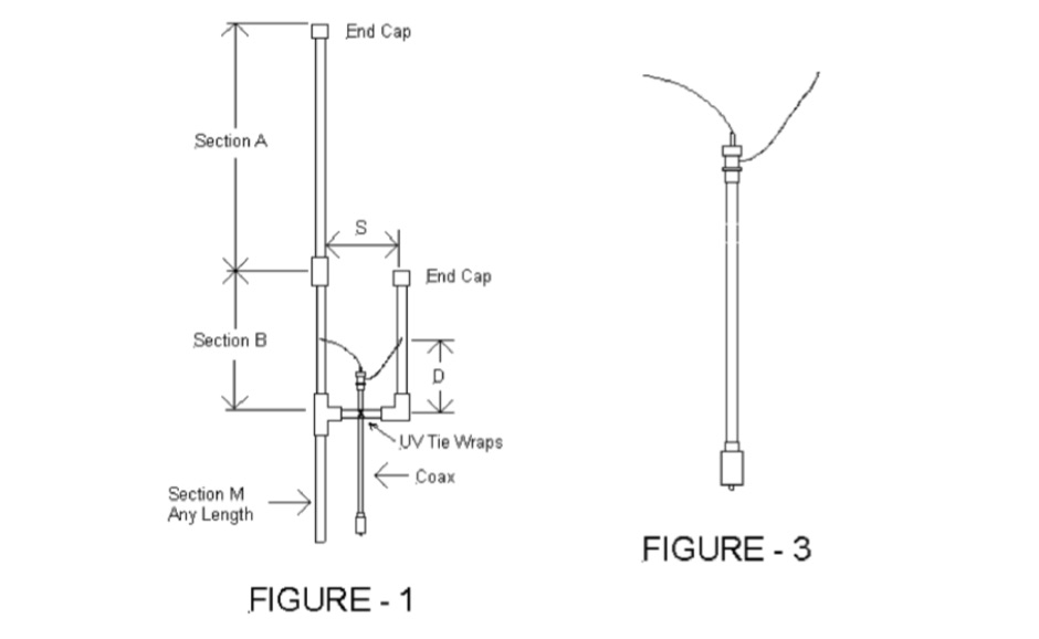 Conejo Valley Amateur Radio Club, article edited by Rory Eikland, KG6HCU and Ken Larson, KJ6RZ, they have had excellent experience building and using J-Pole antennas, and share their experience on planning VHF and UHF Jpole antennas.
 -
 A 10-meter J-Pole antenna, detailed in QST February 1950, offers a straightforward solution for hams operating with restricted space. This design, originally presented by W1BLR, is a **half-wave radiator** fed by a quarter-wave matching stub, providing a low-angle radiation pattern beneficial for DX. The article describes building the antenna from readily available materials like copper pipe, emphasizing its simplicity and effectiveness for **single-band operation**. The J-Pole's inherent design provides a good impedance match to 50-ohm coaxial cable without the need for an external tuner, a significant advantage for portable or minimalist stations. Its nondirectional pattern ensures coverage in all directions, making it a versatile choice for general operating on the 28 MHz band. The construction plans are clear, allowing even those with basic workshop skills to assemble a functional antenna.
 -
 All copper J-Pole antennas for sale. 6 meter, 2 meter, 222 MHz, 440 MHz, LPFM, Marine, GMRS. Includes a construction plan in pdf format if you wish to build your own antenna.
 -
 Presents the design and construction details for a VHF bicycle-mobile antenna, originally published in QST. The antenna utilizes a modified _Arrow J-Pole_ design, adapted for portable operation on a bicycle frame. Performance characteristics include a reported **1.5:1 SWR** across the 2-meter band, demonstrating effective impedance matching for typical handheld transceivers. Construction involves readily available materials, emphasizing lightweight components suitable for mobile deployment. The document provides a parts list and step-by-step assembly instructions, detailing the radiator and ground plane element lengths for optimal resonance at 146 MHz. Mechanical considerations for mounting on a bicycle are also addressed. The resource covers practical aspects of integrating the antenna with a bicycle, including cable routing and securing methods. It offers insights into achieving reliable VHF communications while operating in a mobile, low-power environment, making it relevant for field day activities or casual portable operation.
 -

-
 Yo5ofh j-pole antenna plans for 2 and 6 meters
 -
 A _Topfkreis_ antenna, also known as a "bicycle pump" antenna, is presented as a simple vertical design for the 70 cm band. This variant of the J-pole antenna is notable for not requiring a ground plane, simplifying deployment. The construction details specify using aluminum tubing for the radiating element, with precise measurements for the quarter-wavelength outer tube (32 mm diameter) and the three-quarter wavelength inner sliding tubes (10 mm and 8 mm). Feeding is via a 50-ohm coaxial cable connected 90 mm from the base of the central tube. This design can achieve a gain of **4 to 6 dB** when properly tuned using the adjustable radiating element. The article details the fabrication of a critical aluminum washer, suggesting a method using a hole saw and a drill press as a lathe for precise adjustment. The illustrated example is specifically for the 70-centimeter band, and the author, Pop, clarifies construction points in the comments, including material choices and assembly techniques, ensuring a robust build for VHF/UHF operation.
 -
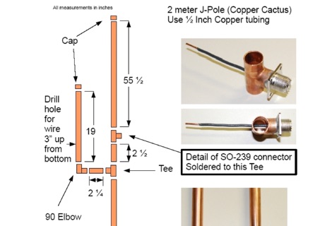 A J-pole antenna plan made using a half inch copper tubing
 -
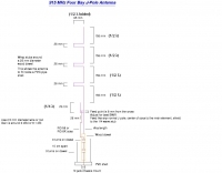
-
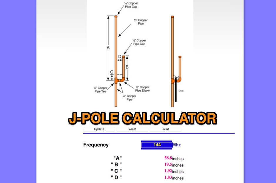 An online J-Pole antenna calculator that need just to input the frequency and calculates in inch size of each element
 -
 Ground Plane - 1/4 wave vertical, J-Pole, 3 Element Yagi Beam and simple antenna supports
 -
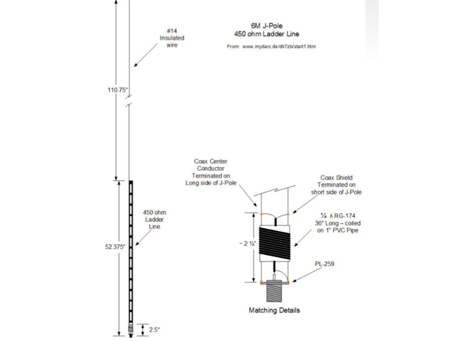 A J-pole antenna plan for 50 MHz based on the DK7ZB design
 -
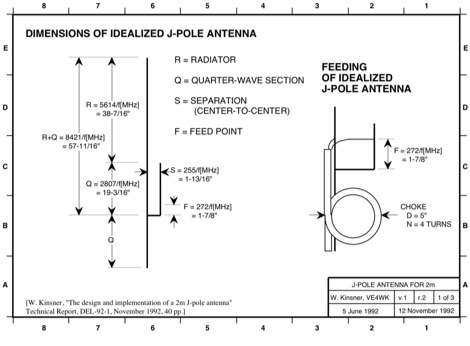 A 144 to 148 MHz J-pole antenna, optimized for base station use, is presented with detailed construction plans. This slim, omnidirectional, half-wave antenna is fed at the end through a quarter-wave shorted transmission line, drawing inspiration from the classic _Zepp antenna_. The design emphasizes achieving a 1:1 VSWR and good efficiency on the 2m band, noting that even a one-percent error in calculation can significantly impact performance. The article provides specific dimensions in inches for the radiator, quarter-wave section, and feed point, along with a parts list for construction from inexpensive materials, estimated at approximately **$10** total cost. The resource offers practical construction tips covering copper pipe selection, L and T joint variations, and detailed soldering instructions using a propane torch. It addresses feedline attachment, the critical role of a four-turn, _5-inch diameter_ choke to prevent coax radiation, and proper antenna fastening techniques, including grounding for lightning protection. The author explicitly advises against scaling the design for other bands due to potential efficiency loss and offers guidance on corrosion protection. The antenna design has been released into the public domain for private amateur use.
 -
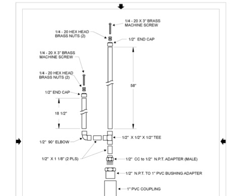 Complete plan for making a 2-meter J-Pole antenna. This drawing in PDF File includes a detailed list of the parts needed to assemble the Jpole antenna for 144 MHz.
 -
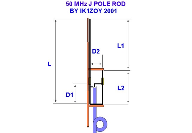 A j-pole antenna plan with drawings and dimensions that can help you on building your own j-pole antenna for the six meters band
 -
 The Slim Jim Antenna Calculator is an online tool that helps hams design a Slim Jim antenna for any desired frequency. This extended version of the J-Pole antenna design does not require a ground plane and is perfect for mounting inside PVC piping. The calculator determines the dimensions of the antenna elements based on the input frequency. Suitable for both receiving and transmitting purposes, this antenna can be easily constructed using common household wiring. The tool provides metric and imperial measurements, along with visual representations of the antenna design for easy reference.
 -
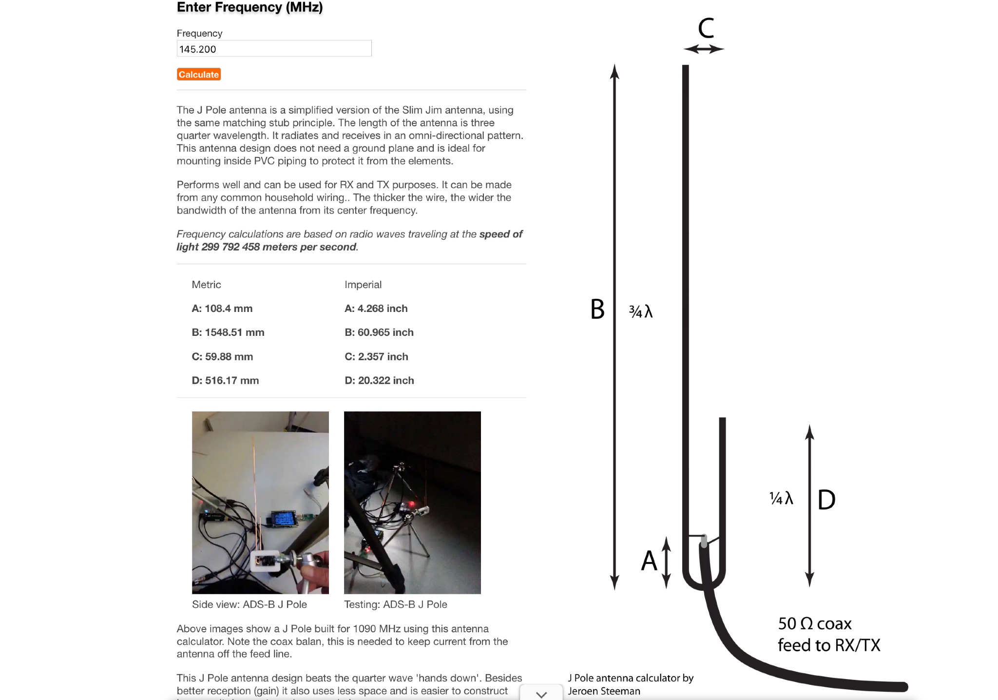 This web page offers an online antenna designer tool for hams to calculate the dimensions needed to construct a J Pole antenna for any desired frequency. The J Pole antenna is a simplified version of the Slim Jim antenna, radiating and receiving signals in an omni-directional pattern. It does not require a ground plane, making it suitable for indoor mounting. With the ability to be made from common household wiring, this antenna performs well for both receiving and transmitting purposes. The calculator is based on radio waves traveling at the speed of light and provides metrics in both imperial and metric units.