Search results
Query: k 40 parts
Links: 22 | Categories: 0
-
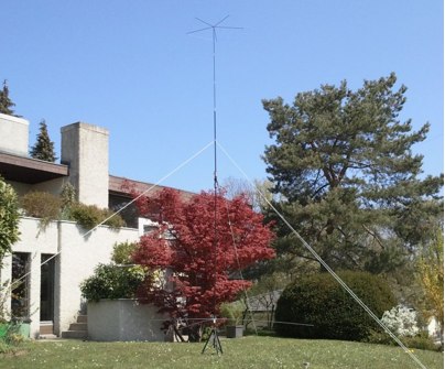
 Details the construction of a **multiband vertical** antenna, specifically designed for stealth operation in a rented property, covering 80m, 60m, 40m, and 30m. The author, N3OX, leverages a 12m Spiderbeam telescoping fiberglass pole as the primary support, noting its sturdiness compared to typical fishing rods while remaining light enough for quick deployment and takedown. The radiating element is a 14 gauge Flex-Weave wire, attached to the pole's top with a rubber grommet, and fed by 27 bare 18 gauge radials spread across a 40-foot square backyard. N3OX describes the impedance matching solution, opting for custom-built L-networks over a remote tuner to enable fast bandswitching. Using an MFJ-259B and EZNEC modeling, base impedances were measured and component values calculated with G4FGQ's L_TUNER and SOLNOID_3 programs. The 80m coil is wound on a 3.5-inch PVC form, while the 30m, 40m, and 60m coils are air-wound, self-supporting #10 wire. Variable capacitors are incorporated for 40m and 30m shunt elements, with the 60m impedance matched by a series inductor. The project includes a **servo-controlled** homebrew band switch, utilizing a two-pole 12-position ceramic wafer switch for remote operation, addressing the limited 80m bandwidth. The entire matching network is housed in a weather-resistant shelter constructed from lumber and aluminum flashing. N3OX reports good DX results at 100W, estimating the total cost between $150 and $250, depending on existing parts.
 -
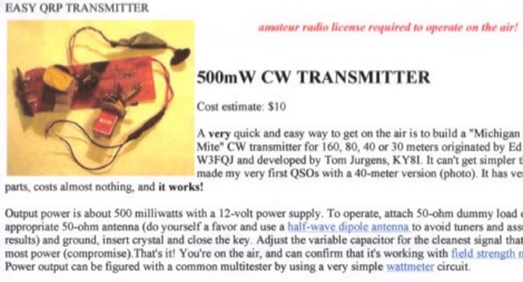 A very quick and easy way to get on the air is to build a "Michigan Mighty Mite" CW transmitter for 160, 80, 40 or 30 meters. It can't get simpler than this. It has very few parts, costs almost nothing, and it works! Cost estimate $10 by VE6WTF
 -
 Vintage and reproduction electronic parts specialist - antique radio dials and knobs, 1940-1970 era phonograph cartridges, needles, idler wheels.
 -
 Vintage and reproduction electronic parts specialist - Antique radio dials and knobs, 1940-1970 era phonograph cartridges, needles, idler wheels.
 -
 This simple 30m QRSS beacon is built entirely out of junkbox parts, the only component purchased specifically for this project was the 10,140kHz crystal. Hans Summers' 30m QRSS beacon project emphasizes simplicity and low cost, built almost entirely from reused parts. Key components include a 10,140kHz crystal, a 2N3904 transistor from a broken DVD player, and an ordinary LED used for frequency shift. The oscillator is stabilized in a polystyrene box, with power amplification driven by recycled copper PCB. Output power peaks at 360mW, and a custom 50-ohm dummy load manages heat. Though aesthetically unconventional, the beacon works effectively, fulfilling the project's low cost aim.
 -
 A vertical dipole for the 40 meters band made by using some buddipole parts and adding capacities on both ends by HB9MTN
 -
 The **HFRadioSales.au** resource provides a commercial outlet for amateur and commercial radio operators seeking HF SSB equipment and related services. It focuses on the Australian market, offering new and refurbished transceivers, antennas, tuners, and a wide array of spare parts for brands like Codan, Barrett, and Qmac. The site details its role as a licensed dealer for new Barrett Communications and Codan radio and antenna systems, including specific models such as the Barrett 4050, 2050, and 950, and Codan Envoy and NGT series. This platform supports various applications, including vehicle, 4WD, outback, marine, and base station setups, catering to networks like HF Radio Club, VKS737, and RFDS. It also features commercial-grade antennas from Bushcomm, such as the BBA100C and SWC100, available for fast shipping from their Queensland warehouse. The site includes an FAQ section with general information on mobile HF communications in Australia and timelines for specific transceiver models.
 -
 Replicating vintage radio components addresses the challenge of restoring classic receivers and transmitters to their original aesthetic and functional condition. Many historical radios, particularly those from the _Golden Age of Radio_ (1920s-1940s), suffer from brittle or missing control knobs and trim pieces, making authentic restoration difficult. This resource focuses on manufacturing new parts that precisely match the originals, ensuring period-correct repairs. The service offers a vast catalog of reproduced items, with thousands of molds created since 1987. This extensive inventory includes a wide spectrum of knobs and pushbuttons, along with some plastic escutcheons, grills, and handles. The meticulous reproduction process ensures that restorers can find accurate replacements for brands like Philco, Collins, and Atwater Kent, preserving the historical integrity of these valuable pieces of radio history. The owner, Larry Bordonaro, has been in business since 1987, demonstrating deep experience in this niche.
 -
 Calnet a multi repeater amateur radio system serving most of California and parts of Nevada. The Calnet system consists of numerous fulltime linked 440 MHz repeaters connecting San Diego to San Francisco and Lake Tahoe.
 -
 Examines the historical role of telegraphy within Canadian railway operations, detailing the evolution of communication systems crucial for train dispatch and coordination. It covers the technical substance of railway telegraphy, including equipment, operational procedures, and the personnel involved, such as agents and operators. The resource provides insights into the **F59PH locomotive** history, development, and components, alongside diagrams of various parts like antennae and traction motors. The content also explores the practical application of these systems by documenting specific railway events, such as the CPR Galt Sub operations from 1895-1971 and GO Transit's operational history. It includes photo galleries, schematics, and diagrams of locomotives and cab cars, offering a visual and technical comparison of different railway equipment. The site also features information on **GO Transit** rolling stock, including MP40s and commuter coaches, providing a historical context for railway communication and transportation.
 -
 This simple 30m QRSS beacon is built entirely out of junkbox parts, the only component purchased specifically for this project was the 10,140kHz crystal.
 -
 A vertical antenna project for the 7MHz made with some spare parts. Based on a broken 20 foot fishing pole, it is based on a good ground system made with radials and a capacitive hat done to increase the global radiation resistance of the antenna. A custom loading coil is also included in this project to perfectly tune the antenna to the CW portion of the 40 meters band.
 -
 The m0xpd keyer project utilizes a PIC16F628A microcontroller, offering Iambic A and B modes, adjustable speed from 5 to 40 WPM, and variable weight control. It incorporates a sidetone generator with adjustable frequency and volume, along with a PTT output for transceiver control. The design includes a 16-pin DIL IC socket for the PIC, a 3.5mm stereo jack for the paddle, and a 3.5mm mono jack for the PTT output. Powering the keyer requires a 9V DC supply, which is regulated down to 5V for the PIC. The circuit board layout is designed for through-hole components, facilitating home construction. A detailed schematic and a parts list are provided, guiding builders through the assembly process. The project also discusses the firmware programming for the PIC16F628A, essential for the keyer's functionality. Construction details cover component placement and wiring, ensuring proper operation. The keyer's compact size makes it suitable for portable or shack use, providing a reliable CW interface.
 -
 The WB5RVZ Genesis Radio G40 build log documents the construction of a 5W QRP 40m SDR transceiver kit, detailing each phase of assembly from power supply to RF filtering. It provides specific component lists, parts placement diagrams, and testing procedures for stages like the local oscillator, Tayloe detector, and RX op-amps. The resource highlights discrepancies between documentation versions and offers practical advice for builders, including a "virtual build" approach to preemptively address potential ambiguities in component identification and placement. It also addresses a specific "VK6IC Fix" for early board revisions, involving trace cuts and jumper wires for improved performance. The build log presents measured voltages and expected current consumption for various stages, such as the 4.9-5.0 Vdc on the 5V rail and under 100mA for RX current. It outlines critical adjustments like image rejection tuning, a common procedure for direct conversion receivers. The resource also includes practical tips for handling components like the 2N3866 transistor and its heatsink, emphasizing pre-assembly. It details the winding of two 1.45 uH toroidal inductors on T50-6 cores with 17 turns of #20 AWG wire, crucial for the RF path.
 -
 Complete collection of the four main parts of this excellet research on modelling and designing half wave dipole antennas for 40 meters band, covering all aspects beginning from full wave length antennas, to shortened, loaded and reshaped dipoles
 -
 The purpose of this webpage is to document an attempt at this project starting with the 80m core receiver first and also having the parts on hand for then adding the first dual conversion band (40m)
 -
 Make your own dipole for 40 and 80 meters band, assembling standard product parts like 40 meter traps, the 1:1 balun and insulators
 -
 Constructing an effective antenna support system often involves safely elevating wire antennas into trees or over obstacles. This resource details the build process for the WT8WV "Colossus" air cannon antenna launcher, a pneumatic device designed to project a pilot line over elevated structures. It specifies the use of readily available PVC pipe components and standard hardware, outlining the exact materials required and providing step-by-step assembly instructions for a robust, low-cost solution. The article presents a practical alternative to traditional methods like slingshots, emphasizing the launcher's utility for Field Day operations and general antenna deployment. It includes a comprehensive list of parts, such as 2-inch and 1-inch PVC pipe, various fittings, a sprinkler valve, and a bicycle pump valve, detailing their integration into the final assembly. The total cost for materials is estimated at around $40 per unit, making it an accessible project for many radio amateurs. Crucially, the guide incorporates essential safety precautions for operating a pneumatic launcher, covering aspects like pressure management and projectile selection. It also features multiple photographs illustrating the construction phases and the completed device, offering visual clarity to aid builders in replicating the design.
 -
 Demonstrates the construction and portable deployment of a 40-meter horizontal loop antenna, often referred to as a "Sky Loop" or "DX-Buster." The design adapts a full-wavelength horizontal loop for field use, eliminating the need for traditional insulators by employing four 5-meter heavy-duty _squid poles_ and metal post bases for support. This setup facilitates rapid assembly, crucial for portable operations, with the antenna wire length specified at approximately 43-45 meters for optimal 40-meter band performance. The resource details the specific construction methodology, including winding the antenna wire around rubber caps on the squid poles and securing it with electrical tape. It provides a parts list and assembly techniques, focusing on minimizing components for ease of transport and quick setup. The article, originally published in the February 2013 edition of the Central Coast ARC "Smoke Signals" magazine, reflects practical experience. This documentation offers a field-deployable 40-meter loop antenna solution, utilizing readily available components like fiberglass squid poles. It presents a practical approach for operators seeking a robust, portable antenna for the 40-meter band, emphasizing simplicity and efficiency in its design and deployment.
 -
 This page contains detailed notes on repairing and aligning the Kenwood TS-440S HF radio. The author shares their experience repairing several TS-440S radios, highlighting common issues and repair techniques. The page also discusses parts availability, modifications, and the radio's performance for digital modes like FT8 and JT65. Aimed at ham radio operators interested in repairing and maintaining vintage HF radios, this page provides valuable insights and tips for working on the Kenwood TS-440S.
 -
 A dual insert microphone design for the Icom IC-7300 transceiver utilizes a **Besson BZ2400 M4 Rocking Armature** insert for frequencies from 500 Hz to 3 kHz, exhibiting a rising response of approximately 11 dB. A generic Electret Condenser insert, powered by the transceiver's microphone line, covers the low-frequency range from 100 Hz to 500 Hz. A Low Pass Filter is incorporated after the Electret insert to prevent frequency overlap, and a pre-set potentiometer (VR1) adjusts the low-frequency response, balancing the output of both inserts. The design emphasizes a "Close Talking" arrangement and addresses audio "colorization" by housing the Besson insert in a thick rubber holder with a foam boot, separate from the circuitry, with the Electret insert also wrapped in a foam boot. Critical importance is placed on using the correct BZ2400 M4 insert with 12 holes in its face plate. The frequency response table for the BZ2400 M4 insert shows 0 dB at 500 Hz, rising to +11 dB at 3000 Hz, while the Electret insert with the Low Pass Filter provides 0 dB at 100 Hz, rolling off to -9 dB at 500 Hz and -50 dB at 3000 Hz. This combination ensures a broad, balanced audio spectrum for SSB operation. The project includes a circuit diagram, a comprehensive parts list detailing components like a 1 Henry iron-cored inductor (L1) and various capacitors, and a board layout within the metal tube. The completed unit provides a tailored audio profile for the IC-7300, enhancing transmit audio quality.
 -
 The W6PQL 23cm Beacon Project describes a **1296 MHz** beacon designed for microwave propagation studies and equipment testing, capable of 30 watts output. It utilizes a PIC 16F628A microcontroller to generate CW and FSK keying for a crystal oscillator, followed by a series of frequency doublers and triplers to reach the target frequency. The final power amplification stage employs a Mitsubishi M57762 module, providing a robust 10-watt RF output. The design emphasizes stability and reliability for continuous operation, with the microcontroller code, written in assembly, provided for customization of the beacon's callsign and message. Originally located in CM97am and aimed at 140 true, the beacon used four 4-foot Yagis stacked vertically for a total ERP of 3kW. The article includes schematics, parts lists, and construction notes to guide builders, along with antenna pattern measurements. Although the beacon itself is no longer in service as of August 2010, the detailed documentation remains a valuable reference for amateur radio operators interested in building similar **microwave** projects or understanding beacon operation.