Search results
Query: lcd controller
Links: 14 | Categories: 0
-
 The project details a DIY SWR/Wattmeter designed around an _Arduino Uno_ shield, providing capabilities to measure RF power from 2 to **200 watts** and Standing Wave Ratio (SWR) for HF amateur radio bands. This construction features a compact design, integrating the measurement circuitry directly onto a custom PCB that interfaces with the Arduino Uno microcontroller. Key components include a directional coupler for sensing forward and reflected power, precision rectifiers, and analog-to-digital conversion for processing RF signals. The Arduino firmware handles calibration, calculations, and displays the results on an integrated LCD, offering real-time feedback on antenna system performance. The design prioritizes simplicity for homebrewers. Performance specifications indicate accurate readings within the **2-200W** power range, suitable for typical QRP to medium-power HF operations. The project provides schematics and a basic overview of the software logic.
 -
 The project details modifications to an ARK-40 QRP CW transceiver kit, specifically replacing its original thumbwheel frequency selectors with a **BASIC STAMP BS-II microcontroller** and an optical shaft encoder. The redesigned control circuitry outputs a BCD code to the ARK-40's synthesizer, enabling more convenient knob-type tuning. This modification significantly alters the user interface, moving from discrete frequency selection to continuous tuning. Operating frequency is presented on an LCD readout, offering two distinct display modes: a "bandspread dial" mode that simulates an analog dial scrolling across the display in 1 kHz increments, and a conventional digital readout with 100 Hz resolution. Pushing the main tuning knob toggles between these modes, providing both rapid band traversal and fine-tuning capabilities. The software for the BASIC Stamp is written in P-Basic, addressing the challenge of accurate analog dial simulation. Physical modifications include fabricating a custom PC Board for the STAMP, mounting it with an L-bracket to the optical encoder, and creating a new front panel. The front-mounted speaker was relocated to accommodate the new tuning knob and display, transforming the **ARK-40 transceiver** into a more user-friendly rig with its built-in CW keyer and 5 watts of power.
 -
 A controller for the miniVNA using an Arduino UNO and touch screen color graphic LCD display
 -
 Amateur Television products, online store for ATV transmitters receivers, LCD controllers, wireless cameras, video senders, accessories, power amplifiers based in UK
 -
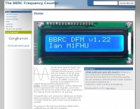 PIC micro controller based frequency counter with LCD readout
 -
 Accurate frequency measurement is crucial for amateur radio operators, particularly when building or troubleshooting transceivers and test equipment. This resource details the construction of a _PIC microcontroller_-based frequency counter, providing a practical solution for precise frequency display. The design incorporates an LCD readout, offering clear visual feedback of measured frequencies. The counter can operate as a standalone unit, useful for general bench testing, or be integrated directly into a receiver. Its built-in offset functionality allows for seamless integration, enabling the display of the received signal frequency rather than the intermediate frequency. The project focuses on accessible components and construction techniques, making it suitable for homebrew enthusiasts. Key features include a measurement range up to **50 MHz** and a compact form factor.
 -
 A DIY Automatic Band Decoder (ABD) project, designed for dual-radio operation, addresses the common challenge of integrating band data with older transceivers lacking dedicated outputs. This particular build utilizes an AVR AT90S8515 microcontroller and a 16x2 Liquid Crystal Display (LCD) to provide band information, specifically targeting Kenwood rigs via a computer's LPT port. The design aims for cost-effectiveness while maintaining functionality, offering a solution for hams seeking to add automatic band switching capabilities to their station without significant expense. The project outlines the core components required, including the microcontroller, LCD, and an enclosure, noting that the Printed Circuit Board (PCB) fabrication and AVR programming might present challenges for some builders. It details the input requirements, such as a four-pin input and PTT for each radio, along with a 13.8V DC power supply. The decoder provides 2x6 outputs capable of sinking 500mA, suitable for controlling external devices like antenna switches or filters. Despite the original unit being damaged by a lightning strike in 2004, the author confirms its successful operation prior to the incident and mentions plans for a revised version. The resource includes a schematic in PDF format and images of the finished PCB and assembled unit, demonstrating the practical implementation of the design.
 -
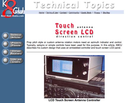 In this article, K8CU describes his custom design that uses an embedded controller and touch screen LCD panel.
 -
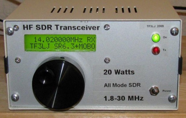 This project describes a DIY all band HF SDR transceiver. Built around a Softrock 6.3 kit, it boasts a 20W homebrew amplifier and ATmega168 microcontroller for USB control. An LCD displays frequency, power, and SWR. Automatic LPF selection and SWR protection enhance functionality. Compatible with Rocky and PowerSDR software, this project provides a cost-effective and powerful HF SDR transceiver for hobbyists.
 -
 A homebrew spectrum analyzer, the Specan, provides a crucial measurement capability often missing from the typical amateur radio shack, allowing for detailed analysis of RF signals up to 70 MHz. This double-conversion superheterodyne receiver design incorporates 112 MHz and 12 MHz intermediate frequencies, utilizing an _Si570_ as the local oscillator for fine tuning down to 1 Hz steps. It offers two resolution bandwidths: 300 KHz for broad spectrum sweeps and 1 KHz for precise close-in distortion measurements, achieving an 80 dB spur-free dynamic range at 1 KHz resolution. The project, a reboot of the classic _W7ZOI/K7TAU_ design from November 1998 QST, integrates an _Arduino_ microcontroller for controlling the Si570, managing a front-panel LCD, and communicating with a PC for spectrum plotting. This approach significantly reduces cost compared to commercial units, making advanced RF diagnostics accessible to homebrewers. The Specan can measure carrier suppression, VFO cleanliness, antenna VSWR, transmitter harmonics, and filter passband shapes, providing insights beyond what an oscilloscope or frequency counter can offer. Construction emphasizes modularity and careful shielding, with each stage built and tested individually on unetched copper clad board. The design includes detailed instructions for integrating the Arduino, building the Si570 oscillator, and aligning the various modules, often using the Specan itself for calibration. It requires a well-regulated linear power supply and can be built with common tools and readily available components, making it a practical and rewarding endeavor for those looking to enhance their RF test bench.
 -
 An **Arduino LC Meter** provides an accessible solution for precisely measuring inductance and capacitance values, crucial for RF circuit design, filter tuning, and troubleshooting in amateur radio applications. This project details the construction of a low-cost, accurate instrument using readily available components, making it an attractive alternative to commercial units for hams and electronics enthusiasts. The build process involves assembling a resonant circuit, integrating an Arduino microcontroller for frequency measurement, and displaying results on an LCD. Key components include an Arduino Uno, a 16x2 LCD, a 74HC14 Schmitt trigger inverter, and a few passive components. The design leverages the Arduino's processing power to calculate L and C values from resonant frequency shifts. Calibration procedures are outlined to ensure measurement accuracy, which is vital for critical RF work. The project includes schematics, a parts list, and the necessary Arduino code, enabling hams to construct a functional LC meter for their workbench.
 -
 The Beam project offers various features for controlling antenna rotators, including support for 2 or 4 line LCD displays, software or hardware clocks, open collector drives for azimuth and elevation control, and internal calculations for tracking the sun and moon. It can also track satellites and supports "Flip Mode" for inverted antennas. The 4-line version provides detailed readouts while the 2-line version offers a more compact display. New versions now support PWM and I2C H-bridge modes for adjustable speed control at the end of a move.
 -
 A versatile digital VFO design utilizing the Silicon Labs Si5351a oscillator chip and Nokia 5110/3310 graphics LCD display, operating from 1-160MHz with dual VFO capability. This microcontroller-based system, powered by an ATmega328 processor, features rotary encoder tuning, selectable step sizes, RIT control, and comprehensive band memory functions. Drawing less than 40mA at 3.3V, it significantly improves upon previous DDS designs' power consumption while offering advanced features like S-meter display, VFO lock, and programmable BFO/CIO offsets. The design achieves flexible functionality through simple hardware implementation and efficient software architecture, making it particularly suitable for QRP and portable amateur radio applications.
 -
 LILYGO specializes in the research and development of IoT solutions, offering a diverse range of development boards. Key products integrate LoRa and GPS capabilities, alongside various display options such as LCD and OLED. Specific examples include the _T-SIM / T-A Standard Series_, _T5 E-Paper S3 Pro Lite_, _T-Halow P4_, _T-Dongle C5_, and _T7-C5_. The company also provides the _T-Solar Kit_ and _T-Sim Shield_, catering to diverse project requirements. Hot sales items feature the _T-Display S3_, _T-Embed CC1101_, _T-Deck Plus_, _T-Embed CC1101 Plus_, _T-Deck Plus Meshtastic_, _T3 LoRa32 V1.6.1_, and _T-Display S3 AMOLED_. These boards often incorporate ESP32 microcontrollers, facilitating wireless communication and display functionalities essential for amateur radio digital modes and data telemetry applications. LILYGO provides entry-level sample code for most products, aiding learners in rapid prototyping and deployment. They also offer customization support for specific customer needs, demonstrating a commitment to supporting both individual makers and larger-scale integrations. The company actively participates in events like Maker Faire Rome, showcasing open-source solutions to the global maker community.