Search results
Query: six meters antenna
Links: 40 | Categories: 0
-
 The W5GI Mystery Antenna is a versatile multi-band wire antenna designed for amateur radio operators. It covers frequencies from 80 meters to 6 meters, making it suitable for a wide range of operating conditions. The antenna features a low feed point impedance, allowing for easy matching with most radios, whether or not an antenna tuner is used. Its construction is straightforward, requiring only two vertical supports approximately 130 feet apart, making it ideal for hams without towers. Users have reported excellent performance, particularly on the 20-meter band, where it outperforms similar designs like the G5RV. This antenna is unique in its design, incorporating three half waves in-phase on 20 meters, resulting in a six-lobe radiation pattern. Despite its effective performance, the antenna is challenging to model, which adds to its mystique. The W5GI Mystery Antenna has gained popularity among amateur radio enthusiasts worldwide, with many users praising its ease of construction and effectiveness. Whether you're a beginner or an experienced operator, this antenna offers a fun and rewarding project that can enhance your HF capabilities.
 -
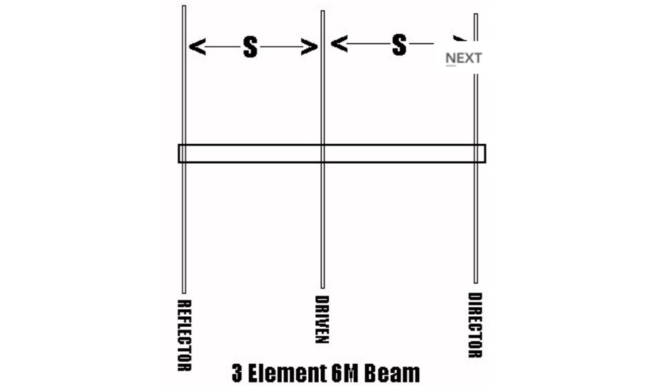 Plans for 3 elements beam antenna and gamma matches
 -
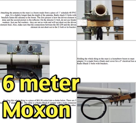 Description and phots of a DIY moxon antenna for six meters band, includes clear pictures, drawings and assembling instruction to build this compact antenna for 50 mhz by N2MH
 -
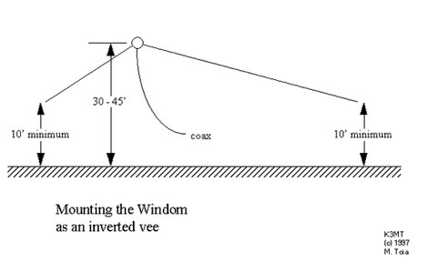 HF Windom antenna, cover 80, 40, 20 15, and 10 meters, antenna design
 -
-
-
 An easy to build Hexbeam antenna built with bamboo sticks for the six meters band
 -
 5 Elem. yagi for 10 meters, 9 element yagi beam antenna for six meters band by ON4ANT
 -
 A homemade antenna plan for a portable yagi beam antenna for the Six meters. Consist of a 3 elements yagi beam design include antenna dimensions, with elements lenght and spacing.
 -
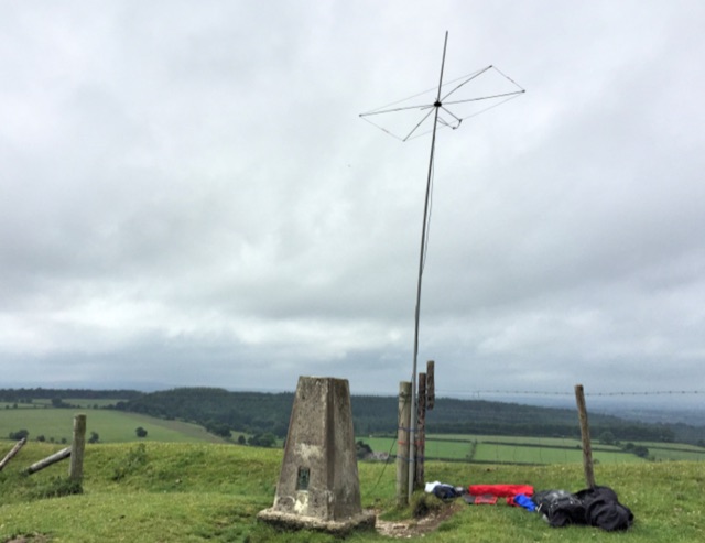
 This is a hex beam designed for six meters. It has three elements with a turning radius of 54 inches. This antenna can be built from low cost materials available from the local hardware store. By WB3BEL
 -
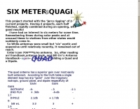
 MQ-1 four band HF beams 20,15,10,6 meters MQ-2 six band HF beams 20,17,15,12,10,6 meters, beam antennas and Hybrid Quad antennas
 -
 The EF0604S is a compact 4 elements yagi antenna plan for six meters band featuring 8.77 dBi gain and a front back gain of 17.89 dB. Article includes elements dimensions and spacing, along to pictures of some homebrewed examples.
 -
 The document details the optimization and construction of the _Maria Maluca_ antenna, a compact 6-band (20m-6m) directional beam. It presents a comparative analysis of shortwave antenna principles, highlighting the efficiency gains achieved by using an open feeder line and tuner as a resonant unit, contrasting this with the losses associated with traps or capacitive loads in multiband antennas. The resource specifically revisits an older South American 2-element design for 10, 15, and 20 meters, applying modern NEC-based software to develop a six-band version. Performance data is meticulously tabulated, showing impedance, free space gain, gain at 12m height, elevation angle, and front-to-back (F/B) ratio for each band from 20m through 6m. For instance, on 15m, the antenna achieves 5.1 dBd free space gain and 13.72 dB F/B ratio. The construction section provides practical guidance on element assembly using aluminum pipes and hose clamps, detailing the use of a heavy-duty glass fiber reinforced polyamide rod for electrical separation and bending strength. It also specifies the use of 450-ohm _Wireman_ line CQ 552 for the transmission line. The document includes diagrams for rod fixing, an air-wound balun, and a vertical elevation diagram for the 15m band, illustrating its DX qualification. It also discusses the antenna's suitability for portable and expedition operations, noting its compact transport dimensions (max 1.50m length, 12 lb weight) and quick assembly time (under 15 minutes). The author, Dipl.Ing. Helmut Oeller, DC6NY, is identified as a source for material kits.
 -
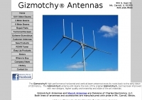 The Charles Gizmotchy high performance horizontal and vertical beam antennas. Two, Six, Ten and eleven meters antennas
 -
 This resource details the construction of a versatile CW/QRSS beacon, designed around a Microchip _PIC16F84_ microcontroller. The project provides a flexible platform for transmitting either standard CW or very slow QRSS signals, making it suitable for LF, VHF, UHF, and SHF applications. It supports two distinct messages, each configurable for speed (from 0 to **127** WPM for CW, or up to **127** seconds per dot for QRSS) and repetition within a six-phase sequence. The core functionality relies on the PIC's EEPROM, which stores all operational parameters, including message content, transmission speeds, phase configurations, and relay control settings. This design allows for parameter modification directly via programming software like _ICProg_ without altering the main program code. The project includes a detailed schematic, a component list, and an explanation of the EEPROM memory mapping for messages, speeds, phase settings, and inter-phase delays. General-purpose outputs (OUT1, OUT2, OUT3) provide dry relay contacts for external control, enabling functions such as power switching, antenna selection, or frequency changes. A 'TRIGGER' input facilitates controlled starts or continuous free-run operation. Sample EEPROM configurations illustrate how to program specific beacon sequences, including message content and relay states.
 -
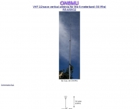
 This vertical antenna consist of a 18 meters telescopic pole and allow operations from 160 to 30 meters band, project by Daniel Zimmerman N3OX
 -
-
-
-
-
 EF0603S is a 3 element portable yagi antenna for six meters band by YU7EF
 -
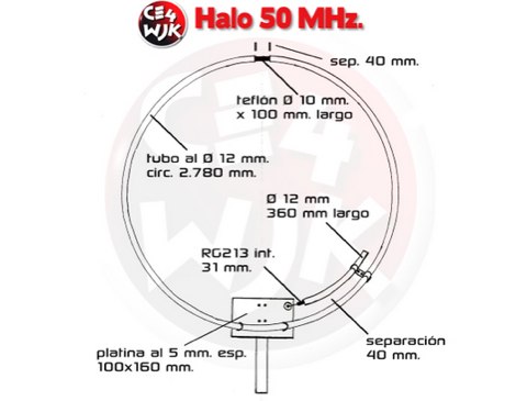
 A vertical antenna for Six Meters band
 -
 An high gain long yagi antenna, seven elements, for six meters band
 -
 Six elements yagi antenna for 6 meters band. This antenna design is based on the QuickYagi 4 software by WA7RAI, uses a 6.5 m boom, feature 12.0 dBi gain and 35dB front/back
 -
 Three Yagi antennas for the six meters band by 9A7PJT. Include a 4 element yagi, a custom design 4 element, and a 5 element yagi with antennas pictures and design.
 -
 Over 150 pages of content are dedicated to maximizing activity on the 6-meter band, often referred to as the _Magic Band_. The resource details various propagation modes, including sporadic E, F2, and tropospheric ducting, providing insights into their characteristics and how to leverage them for DX contacts. It also covers essential equipment considerations, from transceivers and transverters to specific antenna designs optimized for 50 MHz operation, such as Yagis and Moxon antennas. The eBook presents strategies for participating in 6-meter contests and pursuing awards like _VUCC_, offering practical advice on logging software and operating techniques. It includes discussions on software tools useful for predicting propagation and managing contacts, alongside guidance on finding and utilizing DX maps to identify openings. The author, K5ND, shares his extensive experience to help operators achieve successful 6-meter DXing. Specific sections address the code of practice for 50 MHz operations and provide assistance in locating rare DX opportunities. The content is structured to guide both new and experienced operators through the nuances of the band, from initial setup to advanced operating strategies.
 -
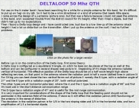
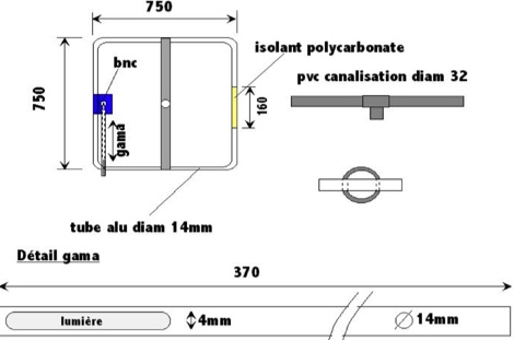
 A homemade delta loop antenna for six meters band in German
 -
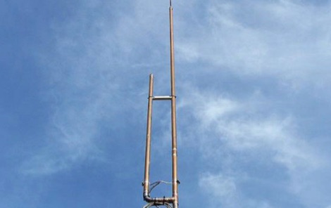 A homemade j-pole antenna for six meters band, designed to work on local repeaters, and working on the 52-53 MHz. Includes a list of needed materials and detailed description on assembling the copper tubes used to build this antenna.
 -
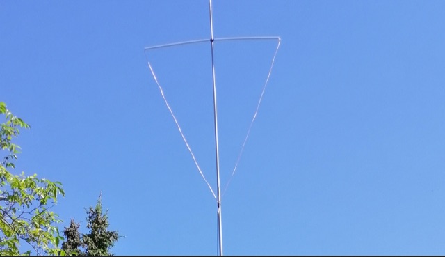
 An Hentenna project for the six meters band. The standard size of standard hentenna is width 1/6 wavelength x height 1/2. The antenna build in this project is a full wavelenght antenna for the 50 MHz providing a 6.8 dbi gain.
 -
 A 30 cm antenna for the six meters band in japanese
 -
 A j-pole antenna plan with drawings and dimensions that can help you on building your own j-pole antenna for the six meters band
 -
 Bring the six meters with you during your hoilidays. This article features a portable moxon antenna for 50 MHz used for sota portable operatios
 -
 This antenna is designed for 40, 80 and 160 meters to complement a tri-band beam normally taken on DX peditions for 10, 15 and 20 meters, so six bands can be worked with only two antennas.
 -
 A 14.12 dBi gain three elements cubical quad antenna for the six meters band. This Quad Antenna design page include a MMA model available to download and dimensions for each element.
 -
 A 4 element Yagi Antenna for six meters band
 -
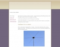
 This article details a ham radio operator’s experience setting up HF antennas in an antenna-restricted community. Initially using an AEA Isoloop magnetic loop for QRP PSK, the author later built an attic antenna system, including dipoles for multiple HF bands and a slinky dipole for 40 meters. The setup allowed for operation on six bands with acceptable VSWR. Despite space constraints and some compromises, performance was effective. The article highlights practical strategies, emphasizing experimentation and antenna modeling for optimizing performance in limited-space environments. A valuable guide for ham radio operators facing similar restrictions.
 -
 Explore the design and testing of a cage dipole antenna for 6 meters. Through innovative construction, witness a remarkable 77% increase in bandwidth and improved impedance characteristics.
 -
 This is a 50 MHz WebSDR receiver, located in Ashford, CT, USA FN31VU using a deltaloop turnstile horizontally polarized omnidirectional antenna.
 -
 A project for a six meters Yagi beam antenna, built mainly for portable operations. This is a 4 element Yagi beam with a 4 meters boom.
 -
 Discover the secrets of Six Meters with this comprehensive eBook by Jim Wilson, K5ND. Learn about the magic of 6-meter DXing, including propagation, antennas, equipment, operating software, and more. Whether you're a beginner or an experienced ham radio operator, this book covers everything you need to know. With over 8,000 downloads, this updated version includes new chapters on FT8/FT4, MSK144, and Q65 modes, as well as contesting, rover operation, and awards. Get your hands on this valuable resource and enhance your 6-meter DXing experience today.