Search results
Query: transmitter watt
Links: 27 | Categories: 0
-
 Monitoring shortwave broadcast stations effectively requires accurate schedule information to identify transmissions. This online utility offers a straightforward, graphical interface designed to search for and display current shortwave radio broadcasting schedules. Users can precisely filter results by frequency, specific language, broadcaster, time of day, and even by shortwave band, which simplifies the process of pinpointing desired content. The database, last updated on March 26, 2023, details station callsigns (e.g., BBC), start and end times in UTC, days of the week, broadcast language, transmitter power in kilowatts, and azimuth. Crucially, it includes the precise geographical coordinates of transmitter sites, such as Woofferton in the UK or Al Seela in Oman. This data is invaluable for predicting signal paths and optimizing antenna direction for improved reception, a key consideration for serious SWLs. For instance, a search for BBC English broadcasts at 21:04 GMT quickly reveals multiple active frequencies like 17780 kHz from Woofferton, offering a clear overview of current transmissions. The tool processes queries rapidly, returning results within seconds, demonstrating its efficiency for broadcast listening enthusiasts seeking timely information.
 -
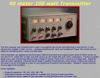
 Presents a crystal-controlled CW transmitter design for the 40-meter band, delivering 5 to 7.5 watts output power. The circuit innovatively employs an _IRF510_ power MOSFET in the final amplifier stage, diverging from conventional bipolar transistors. This design offers high gain, nearly 90% efficiency, and robust resistance to high SWR, allowing 30-second key-down operation into an open circuit without damage. A critical aspect is the precise adjustment of the MOSFET gate bias via a 10K trimmer pot, _R10_, to maintain quiescent current between 5 and 10 mA, preventing thermal runaway inherent to bipolar devices. The prototype was constructed on a _Radio Shack universal board_ and achieved immediate operational success. The design requires a 15-volt Zener diode to protect the MOSFET gate from overvoltage. Component sourcing information is provided, including specific crystal frequencies (7.040 MHz or 7.122 MHz) available from _Dan’s Small Parts & Kits_ or Doug Hendricks. The fixed frequency can be slightly adjusted with a trimmer capacitor. A complete bill of materials, including resistor values, capacitor types, toroid specifications, and transistor part numbers, is detailed, alongside a clear schematic diagram.
 -
 This project shows how to build a 50-ohm dummy load using non-inductive resistors, oil for heat dissipation, and a simple assembly process. It enables accurate transmitter tuning, testing, and power measurement across LF to UHF bands. The setup allows meter calibration by measuring peak voltage, applying diode drop correction, and calculating RMS voltage and power precisely. Parts are inexpensive and widely available. With proper assembly, this dummy load offers extended service life, accurate readings within 2%, and a reliable alternative to costly commercial wattmeters for amateur radio applications.
 -
-
 The article "Exploring the World of 10 Meter Beacons" by Ken Reitz, KS4ZR, provides an in-depth look at 10-meter beacon operations, focusing on their utility for propagation analysis. It details FCC Rules part 97.203 governing beacon stations, including license requirements, power limits (under 100 watts), and the specified band segment of 28.200-28.300 MHz for U.S. operations. The content highlights the diversity in beacon construction, from converted CB radios to home-brew QRP transmitters, and discusses the robust operating conditions these 24/7 stations endure. The resource presents several case studies of active 10-meter beacon operators like Ron Anderson KA0PSE/B, Domenic Bianco KC9GNK/B, and Bill Hays WJ5O/B, detailing their equipment, antenna setups, and typical signal report volumes. It also introduces the NCDXF/IARU International Beacon Project, which features 18 synchronized beacons worldwide transmitting on 28.200 MHz at varying power levels (100W, 10W, 1W, 100mW) to facilitate propagation testing. The article also covers the PropNet Project utilizing PSK31 on 28.131 MHz and the 250 Synchronized Propagation Beacon Project on 28.250 MHz. Practical advice for monitoring includes using the RST reporting method, understanding the impact of the solar cycle on 10-meter propagation, and tips for setting up a personal beacon, such as frequency selection and power output considerations. The IY4M Guglielmo Marconi Memorial Beacon Robot on 28.195 MHz is also mentioned for its automatic QSO mode. The article concludes with a list of other resources for 10-meter beacon information.
 -
 N7KSB used this 1/2 watt CW transmitter, with a roof-mounted ground-plane antenna to work all continents and over 30 countries
 -
 A radio's transmitting power can be concentrated along the horizon by use of a GAIN antenna. Although you may still be transmitting with four watts of power, your effective radiated powerwill be greatly increased. This table shows the effects of antenna gain on a transmitter with 4 watts of transmit power.
 -
 The NCDXF/IARU International Beacon Project operates a worldwide network of 18 high-frequency radio beacons, continuously transmitting on 14.100, 18.110, 21.150, 24.930, and 28.200 MHz. These beacons, initially launched in 1979 with a single station and expanded to the current 18-beacon system in 1995, provide reliable signals for both amateur and commercial users to assess current **ionospheric propagation** conditions. The system's design, construction, and operation are managed by volunteers, covering hardware and shipping costs. The resource details the evolution of the beacon network, including the transition from Kenwood TS-50s transmitters to Icom IC-7200 radios with a new controller design implemented in 2015. It explains how listening for these 100-watt signals, transmitted to vertical antennas, allows operators to determine band openings and optimal propagation paths globally. The content also references three QST articles providing historical context and technical specifics of the beacon project. Practical information includes methods for identifying transmitting beacons via a schedule or specialized software like FAROS and Skimmer, which integrates with the **Reverse Beacon Network** for automated monitoring.
 -
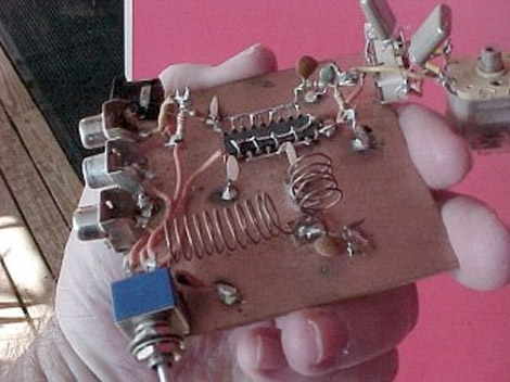
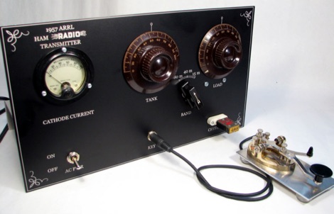
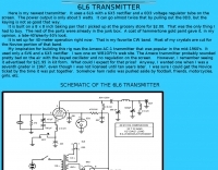 40 meters band 5 watts transmitter, uses a 6L6 with a 6X5 rectifier and a 0D3 voltage regulator tube on the screen.
 -
 A circuit for a 5 milliwatts super QRP morse code transceiver by VE2ZAZ
 -
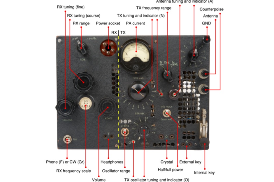 The BP-3 was a valve-based spy radio transceiver, developed during WWII by Tadeusz Heftman of the Polish Military Wireless Unit in Stanmore (UK). It was introduced in 1943 and was intended for use by Agents and Resistance Organisations in Europe. The transmitter produces an output power of 50 Watts in CW
 -
 Antenna tuners are crucial for matching the impedance of antennas to the 50 ohm output impedance of transmitters. The _LDG Z-11 Pro_ is an automatic antenna tuner designed to handle up to 125 watts, making it suitable for a wide range of amateur radio applications. Its compact form factor allows it to pair well with transceivers like the _FT-857D_, providing a portable solution for operators who frequently change locations or setups. The tuner covers the 80 through 6 meter bands, offering a broad impedance match capability. Although it struggles with some loads, it performs well with typical ham antennas, even managing to load an 80 meter dipole on 6 meters. One of the standout features of the _Z-11 Pro_ is its 8000 memory slots, which enable it to remember successful matches and quickly retune when revisiting frequencies. This memory function significantly reduces tuning time, often to less than half a second. The unit is well-constructed, with improved pushbuttons and a sturdy metal case that offers good shielding. However, users should be aware of potential RFI issues and the lack of a power switch, which requires disconnecting the power cord to turn off the unit completely. Overall, the _LDG Z-11 Pro_ is a user-friendly and cost-effective tuner, offering advanced features that enhance its utility in various amateur radio setups.
 -
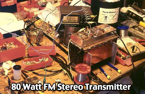 A high quality broadcast transmitter big enough for a medium town
 -
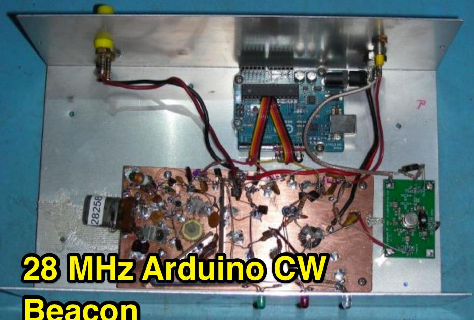 This project involves the construction of a 5 Watt Morse code beacon transmitter that operates in the 28.200 to 28.300 section of the 10 Meter Amateur Radio band. The beacon controller uses an Arduino Uno microprocessor board to produce the three signals that control the transmitter.
 -
 Makers of the The Polar Explorer transmitter, which operates on 9 HF bands from 160 through 10 meters and is capable of 500 watt peak output power on SSB, CW, AM, FM and RTTY. It is intended to be used in conjunction with a transceiver.
 -
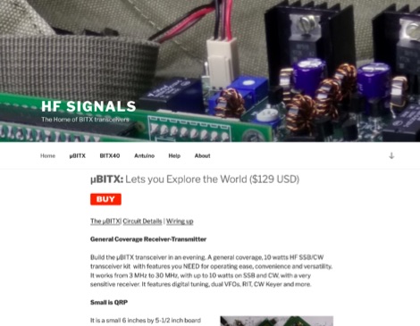 Makers of QRP HF General Coverage Transceivers you can build. The Home of BITX transceivers, uBITX General Coverage Receiver-Transmitter. A general coverage, 10 watts HF SSB/CW transceiver kit with features you NEED for operating ease, convenience and versatility. It works from 3 MHz to 30 MHz, with up to 10 watts on SSB and CW, with a very sensitive receiver.
 -
 A homebrew radio transmitter project, based and inspired by the original 30 Watts input on 80 50 and 15 meters band transmitter by W11CP
 -
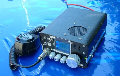 This article describes the construction of a high performance transmitter and receiver for SSB (voice) communication covering the 14MHz (20 meters) high frequency amateur radio band with output range 15 to 20 watts and a top audio sound quality both on transmit and receive.
 -
 The ZS1J/B beacon operates on 28.2025 MHz with 5 Watts output to a half-wave, end-fed vertical antenna, initially installed in 1977 as ZS5VHF near Durban. The 10-meter transmitter is a modified 23-channel CB radio, and the identification keyer uses a diode matrix unit with TTL ICs from the same era. After relocation to Plettenberg Bay in 1993, the beacon has been in continuous service, with additional QRP transmitters later installed for other bands. In 1994, a single-transistor, 80-meter, 0.5-watt QRP transmitter with a half-wave dipole was added on 3586 kHz, followed by a 160-meter, 0.5-watt unit on 1817 kHz. A 30-meter, 0.5-watt transmitter was installed in 1996, operating on 10.124 MHz. In 2002, a 40-meter QRRP beacon on 7029 kHz, with an output of 100 microwatts, achieved DX reports up to 1100 km from ZS6UT in Pretoria. Best DX reports for the 80m and 160m beacons came from 9J2BO.
 -
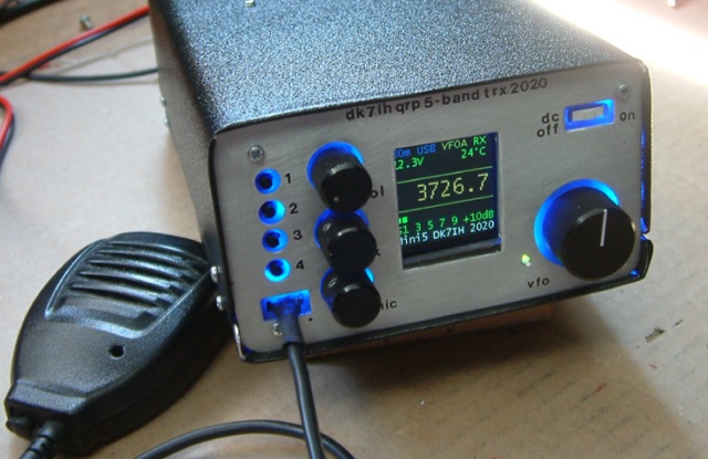 Gimme Five reloaded, a compact 5 band QRP SSB transceiver in SMD technology. This unit covers 5 bands within the amateur radio spectrum (3.5, 7, 14, 21 and 28 MHz). Receiver is a single conversion unit with an interfrequency of 9 MHz. Transmitter uses 5 stages and has got a power level of 10 watts PEP output.
 -
 Thsi article describes a microcontroller driven semi-automatic antenna tuner capable of handling power levels up to 150 watts. The device is a low pass filter tuner manually tuned by setting the optimized L/C combination by hand and then storing the values into the EEPROM of the mictrocontroller to recall them later (seperately for each band from 80 to 10 meters including WARC bands)
 -
 DF0WD/DL4YHF's Longwave Overview details amateur radio operations on the 135.7 to 137.8 kHz segment in Germany. The author outlines the "inofficial" European band plan, specifying segments for QRSS, TX tests, beacons, conventional CW, and data modes. Early LF activities at DF0WD began with a 20-watt CW transmitter, later upgraded to a homemade linear transverter capable of 100 watts, driven by an Icom IC706 on 10.137 MHz. The station's antenna system includes a 200-meter wire, approximately 10 meters above ground, supported by football field light-masts. Despite its length, the antenna's efficiency is noted as very low due to the immense wavelength of about 2.2 km. The author's experience highlights the significant challenge of achieving effective radiated power (EIRP) on LF, estimating DF0WD's EIRP at around 80 milliwatts based on field strength measurements from PA0SE. DF0WD/DL4YHF has successfully worked numerous countries on 136 kHz CW, including DL, F, G, GI, GM, GU, GW, HB9, HB0, LX, OE, OH, OK, OM, ON, OZ, PA, and SM. The author also mentions ongoing efforts to log contacts with CT, EI, LA/LG, and to complete a two-way QSO with Italy, demonstrating persistent activity on this challenging band.
 -
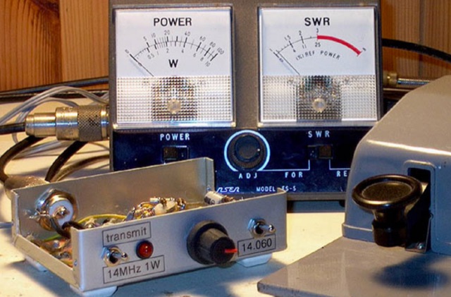 The 1 watt 20 meter QRP transmitter with VXO. This is a nice QRP transmitter that can be used in combination of one of the simple receivers.
 -
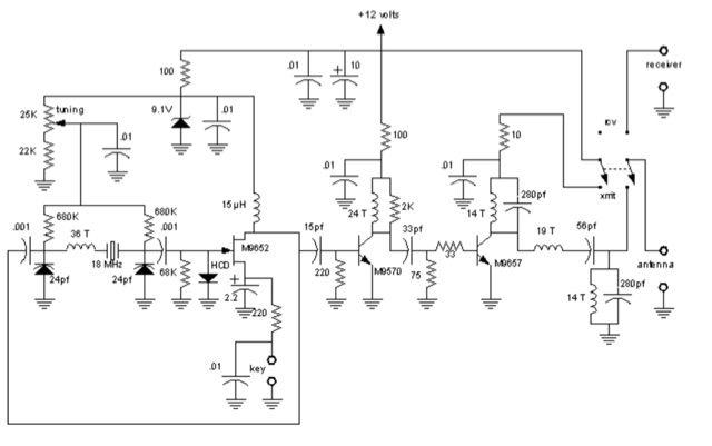 1-watt 17-meter cw transmitter that was originally done about 10 years ago as a club project for RAMS, the Radio Amateur Megacycle Society. It uses a VXO, rather novel at the time. It also uses a bandpass filter at the output rather than the usual lowpass
 -
 QRP is a way of operating that involves using low power transmitters, that are no more than 5 Watts for Morse or data modes, or 10 Watts pep for voice. Introduction to QRP operations
 -
 Learn how to build a simple transmitter called the 'Easy Ten' that can be easily heard at a distance of 10 miles using a random length wire antenna thrown into a tree. This article focuses on working with frequencies in the 3.5 and 7 MHz range without the need for complex setups like coax lines or baluns. The author shares their experience of making contacts across the Pacific Ocean and the United States using just one watt of output power and simple antennas. Discover how to optimize signal output using a homemade level meter made from a DC microameter and a germanium diode.
 -
 Twenty 1-watt carbon film resistors are configured in parallel to construct a 50-ohm **dummy load** for amateur radio applications. The design incorporates a heatsink for thermal dissipation and an **SO-239 connector** for RF input, making it suitable for QRP operations. This budget-friendly project details component selection, soldering techniques, and mounting procedures, achieving a continuous power rating of 10 watts and intermittent handling of up to 100 watts across HF and VHF frequency ranges. The resource provides a step-by-step guide for assembly. This construction offers an economical solution for essential shack tasks such as antenna tuning, transmitter testing, and SWR meter calibration without radiating an RF signal. The utilization of readily available components significantly reduces the overall build cost compared to commercial alternatives, providing radio amateurs with a functional and reliable test accessory. While specific VSWR measurements are not provided, the design prioritizes practical utility for low-power transceiver diagnostics and general RF experimentation.