Search results
Query: vehicle mounting
Links: 14 | Categories: 0
-
 Demonstrates the construction of a **multi-band HF mobile antenna** utilizing a modified CB whip antenna base. The resource details the process of stripping a commercial CB whip, winding a new helical coil with 0.7mm insulated copper wire, and identifying tapping points for various HF bands. It emphasizes the importance of a rugged, slim design for mobile operation, discussing mechanical length, power handling (up to 200 watts), and coil diameter considerations. The article includes a graphic illustrating the antenna's operational principle, where sections of the helical coil are shorted from bottom to top to maintain efficiency and high Q. The resource presents a practical approach to achieving **band switching** without an external tuner, by manually adjusting tapping points on the coil. It provides a table with reference lengths in centimeters from the feedpoint for 7 MHz (40m) through 28.7 MHz (10m), including WARC bands. The author details mounting techniques, suggesting a Diamond bracket for secure attachment to a vehicle trunk, and stresses the critical role of proper grounding for optimal performance. The design allows for operation on 75m and 80m bands by adding a 110mm steel whip.
 -
 Examines the practical considerations and technical challenges of deploying mobile antennas for 10-meter operation, particularly for operators on the move. It addresses the inherently _lossy_ nature of shortened, loaded vertical antennas typically used in mobile configurations, encouraging hams to view these limitations as engineering challenges. The resource provides actionable advice on safeguarding vehicle electronics, selecting appropriate cabling like _RG-213_, and properly grounding antenna mounts to the vehicle chassis. Specific mounting strategies are detailed, including roof, trunk lip, and side-mounting for trucks and vans, along with their respective advantages and drawbacks. It emphasizes the importance of a robust ground plane and suggests methods for improving grounding beyond simple set screws. The article also touches on antenna choices, mentioning "bugcatchers" and "Hamstick types" as viable options for 10 meters. Furthermore, the guide transitions to stationary mobile operation, where antenna options expand significantly. It outlines how to deploy portable dipoles or 2-element beams from a parked vehicle, offering practical tips for assembly, storage, and mast guying using simple materials like a concrete block. It notes that a 5/8 wavelength height, approximately **20 feet** on 10 meters, often yields good short-skip and DX performance, even with a take-off angle above **20 degrees**.
 -
 The ARRL page, titled "The HF Mobile Antenna," serves as a curated index to various _QST_ articles focusing on constructing mobile HF antennas. It presents several projects for the mechanically inclined amateur, suggesting that homebrewed antennas can achieve efficiency comparable to commercial versions. For instance, one entry details a **five-band** antenna for RVs, utilizing a fold-over Hustler 4BTV, while another describes a "Bug Catcher" design for 80 through 10 meters. Further projects include a budget-friendly $20 HF mobile antenna made from PVC and wire, covering 20 through 6 meters, and the "Alpha Special," a multiband horizontal antenna originally for 1960s station wagons, now suggested for mini-vans. The resource also addresses antenna mounting solutions specifically for travel trailers and campers, providing practical insights for those operating from recreational vehicles. Rounding out the collection are the "Connecticut Longhorn," a 75-meter horizontal whip with remote tuning, and its redesign, the "Connecticut Shorthorn," adapted for smaller vehicles post-1970s. This compilation offers a historical perspective on mobile antenna innovation and practical construction guides for various HF bands and vehicle types.
 -
 M0VEY shares insights into constructing a 160-meter mobile DX aerial, detailing the process of sourcing materials and assembly. The project began with a goal to avoid a £50 commercial antenna, instead utilizing a £10 reel of _enamelled copper wire_ and salvaged components like alloy tent poles and plastic water pipe. A friend fabricated a custom stainless steel tube for mounting, featuring a 3/8” thread for a mag-mount, enabling secure vehicle attachment. The aerial's design incorporates four alloy tubes, one plastic tube, and a five-foot whip, engineered to split into two pieces for convenient storage. The loading coil, wound with approximately 115 feet of 0.75mm wire onto a plastic former, was then sealed with blue heat shrink. M0VEY reports successful operation, making contacts across the UK and Europe, with the aerial standing about ten feet tall for local nets at 1.972 MHz and taller for the DX window around 1.845 MHz. Future plans include a base-loaded 160m aerial and an 80m version, leveraging components from the existing _160m DX Mobile Aerial_ to maintain a similar overall size with a smaller coil.
 -
 This resource details the construction of a mobile screwdriver antenna, patterned after the original W6AAQ DK3 design from 1991. It covers the mechanical and electrical aspects of building a robust, multiband HF antenna for vehicular operation. Specific components discussed include the lower mast section, the coil wound on Schedule 40 PVC pipe, beryllium copper contact fingers, the motor drive assembly utilizing a Black & Decker screwdriver, and the capacity hat design with a brass hub and steel wires. The article provides insights into material selection, such as heavy copper tubing and silicone grease for assembly, and addresses practical considerations like coil length limitations for 80m operation due to lathe size. The construction results in an antenna capable of tuning from 6.5 MHz (40m) up to 6m, with slightly reduced range when the capacity hat is installed. The author describes the mounting base with soldered brass nuts for secure attachment and a U-channel bracket for vehicle mounting on a Dodge Ram 1500. The article includes close-up photographs illustrating the coil, contact fingers, drive mechanism with rubber tubing clutches, and the capacity hat assembly. It also mentions the use of Rustoleum hammer finish enamel for painting the copper pipe, indicating attention to durability and aesthetics.
 -
 A 5/8 wavelength mobile whip antenna for 2 meters can be constructed from a 5-foot CB helical whip, requiring the removal of original wire and installation of a new radiating element made from coax braid. The design incorporates an 8-turn loading coil with 5mm spacing, fabricated from the original whip wire, and utilizes approximately 1400mm of RG-58 coax braid for the radiating element to enhance flexibility and bandwidth. Final whip length is approximately **1350mm** from base to braid end, with tuning adjustments made by trimming the braid. Dual-wall 12mm heat shrink, such as _Jaycar WH5643_, is recommended for weatherproofing and stabilization, costing around $4.50 per 1200mm length. Achieving a 1.1:1 VSWR may not be feasible; a 1.5:1 VSWR is considered acceptable. Optimal mobile mounting is centered on the vehicle roof to minimize radiation pattern variations.
 -
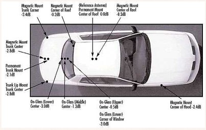 Mobile antenna placement presents unique challenges for the amateur radio operator, often requiring compromises between RF performance and mechanical considerations. This resource from KV5R.COM offers practical insights into achieving effective installations, drawing on real-world experience with different vehicle types. It details how factors like ground plane availability, proximity to vehicle structures, and antenna type (e.g., **HF mobile**, **VHF/UHF mobile**) influence signal radiation patterns and overall system efficiency. The author discusses common scenarios, from sedans and SUVs to trucks and RVs, highlighting the impact of mounting locations such as the trunk lip, fender, or roof. Specific attention is given to minimizing RF interference and maximizing radiated power, crucial for reliable mobile communications. Understanding the interaction between the antenna and the vehicle's metallic body is key to a successful mobile setup, and this content provides a solid foundation for making informed decisions.
 -
 Examines the four basic components of a mobile antenna system: the antenna, coaxial cable, antenna stud, and the mount, emphasizing mount selection as the most complex decision. Modern vehicle designs, including the absence of metal rain gutters and specific trunk configurations, often preclude traditional mirror, trunk lip, ball, or gutter mounts, necessitating universal mount designs. Discusses the economic challenges of designing vehicle-specific mounts due to tooling costs versus production runs, citing exceptions like Dodge Ram hood mounts and GM truck mirror mount brackets. The article acknowledges the difficulty for manufacturers to recommend specific mounts without direct vehicle inspection, given the vast array of vehicle designs and individual installation restrictions. Advises users with mechanical aptitude to study available mounts and assess possibilities directly on their vehicle. Recommends visiting a local communications store for personalized assistance if self-assessment proves difficult, highlighting the value of expert advice to avoid performance issues or equipment damage.
 -
 This resource provides fundamental guidelines for optimizing mobile amateur radio antenna installations. It addresses critical factors such as achieving an adequate ground plane, minimizing common mode current, and reducing ignition noise. Specific recommendations include mounting antennas on the vehicle's roof for superior radiation patterns and utilizing proper feedline routing to mitigate RF interference within the vehicle's electrical system. The content details the impact of antenna placement on Standing Wave Ratio (SWR) and overall radiated power, emphasizing the importance of a solid electrical connection to the vehicle chassis. It also discusses strategies for noise suppression, such as bonding body panels and employing ferrite chokes on power leads. The information presented is practical for hams seeking to improve their mobile station's efficiency and reduce RF-related operational issues.
 -
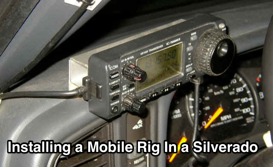 Installing a mobile rig in a vehicle requires careful planning and execution to ensure optimal performance and safety. The process begins with selecting the right equipment, such as the ICOM IC706MKII for low bands and the ALINCO DR-610 for VHF/UHF operations. Proper mounting is crucial; both radios are strategically placed under the back seat of the Silverado, allowing for a clean installation while maintaining passenger comfort. The Hustler antenna, equipped with various resonators, ensures coverage across multiple bands, while the LDG automatic antenna tuner fine-tunes the match for efficient operation. A remote head for the tuner enhances accessibility, making adjustments easier while driving. Each step of the installation is documented to provide insights and tips for fellow operators looking to enhance their mobile setup. The experience shared here reflects practical knowledge gained through hands-on work, aiming to inspire others in the ham community to undertake similar projects.
 -
 A distance of 1/8 lambda between the antenna and the vehicle roof is suggested for optimal performance, with slight adjustments possible to lower the take-off angle for terrestrial contacts. This resource details the adaptation of an _Eggbeater_ antenna for mobile use, specifically for VHF operation, leveraging the car's metal roof as a ground plane. It illustrates the mounting method, repurposing a magnetic ski carrier base, and describes the integration of coaxial relays for polarization reversal, a feature also applicable to UHF versions as discussed in "_Eggbeater Antenna VHF/UHF – Part 2_". This mobile configuration proves effective for satellite communications, such as through the International Space Station (ISS), while also maintaining strong performance for land-based radio contacts. The inclusion of switches with indicator lights for VHF and UHF polarization control, powered by the vehicle's battery, highlights practical considerations for field deployment. The system's adaptability for portable operations underscores its versatility beyond fixed mobile installations.
 -
 The project details the construction of a portable multiband mobile antenna, designed for rapid deployment with an _Elecraft KX3_ for /M operations. It utilizes a coil and the car body as a counterpoise, enabling operation across multiple HF bands. The article presents a table of coil tap positions for 40m, 20m, 17m, 15m, and 10m, along with corresponding SWR measurements, demonstrating an SWR below 1.5:1 on all tested bands. Photographs illustrate the antenna's components, including the coil winding and mounting mechanism, and its deployment on a vehicle. The author provides insights into the antenna's performance characteristics, noting its resemblance to a vertical dipole despite the unconventional ground plane. The resource includes a parts list and construction steps, making it reproducible for other radio amateurs.
 -
 The resource details the construction of a J-pole vertical antenna specifically engineered for motorcycle mounting, addressing the common issue of interference with top cases. It outlines the fabrication process, beginning with an aluminum angle bracket for secure attachment to the lateral support, followed by the creation of the antenna's base from an 8mm threaded rod bent into a U-shape, approximately **40mm** wide. The article specifies the precise method for coaxial cable connections using eyelets and 3mm screws, ensuring robust contact. Further construction steps involve fitting a 10mm aluminum tube onto the threaded rod, with a screw securing the radiating element and establishing core contact. The design prioritizes mechanical stability against vehicle vibrations over fine-tuning SWR with sliding collars. Initial testing yielded a _SWR_ of **1.2** across a significant portion of the band, with improvements noted by optimizing the coaxial braid contact point near the support bracket. The document provides practical insights into material selection and assembly, emphasizing durability for mobile operation. It concludes with aesthetic options, allowing the builder to paint the antenna or retain its natural aluminum finish, making it a functional and adaptable solution for UHF motorcycle communications.
 -
 When installing a mobile antenna, optimal placement significantly impacts performance. Factors such as gain, antenna type, ground plane availability, mounting style, and environment must be considered. Antenna designs, such as 1/4 wave and 5/8 wave, have distinct radiation patterns ideal for specific settings—urban areas or flat terrains, respectively. Ground plane size requirements differ by frequency, impacting effectiveness. Among vehicle mounting options, the car roof center provides the best ground plane and minimal obstruction, ensuring peak performance, especially at higher frequencies like 800 MHz.