Search results
Query: vna
Links: 35 | Categories: 1
-
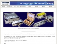
 Homebrew project of a vector network analyser VNA by N2PK
 -
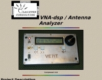 This project is an attempt to build a portable standalone VNA (Vector Network Analyzer).
 -
 This resource details the conversion of an 80m elevated vertical antenna to include 160m operation, focusing on a relay-switched design over a trap-based approach. It presents specific feedpoint impedance values, such as **32 ohms** for 80m and **14 ohms** for 160m, and discusses the challenges of SWR drift encountered with the prior trap system during RTTY contesting. The article thoroughly explains the design choices for elevated radials, referencing _N6LF QEX data_ to debunk common myths regarding radial length and height, demonstrating that non-resonant radials can offer superior current uniformity. The construction section provides practical insights into building the vertical, including guying strategies, material selection from scrap pipe, and weatherproofing the relay assembly. It highlights the use of a common mode choke for the relay switching line, measuring approximately 5K ohms on both 160m and 80m, and details the L/C matching network's role in achieving a 50-ohm match at the end of a 300-foot RG-11 run. The author describes a precise VNA-based radial trimming procedure, achieving resonant values within a 3 KHz range. The content emphasizes the practical application of theoretical antenna principles, particularly concerning the interaction between the vertical element, cap hats, and the matching network. It offers a candid assessment of component selection, such as using junkbox parts and acknowledging the need for future upgrades to static drain resistors. The article serves as a comprehensive case study for advanced antenna builders tackling multi-band vertical designs.
 -
 This article describes a low-cost vector network analyzer that operates from 200 kHz to 100 MHz, and connects to a personal computer using a USB 1.1 interface By Tom McDermott, N5EG, and Karl Ireland
 -
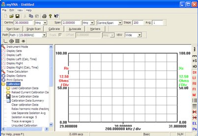
 SimSmith is a highly interactive, real time Smith chart graphing program. Circuits are constructed using drag-n-drop. Load files can be imported from the EZNEC and CocoaNEC antenna simulation software and from the AIM4170 and miniVNApro antenna analyzers. Circuits and load files can be of any size. Key Features: SimSmith is one of the few Smith chart packages which models transmission line losses. SimSmith also allows the description of circuit elements using algebraic equations. SimSmith has only one screen and allows the screen to be resized to increase workspace or readability.
 -
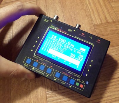
 A controller for the miniVNA using an Arduino UNO and touch screen color graphic LCD display
 -
 Bird Technologies supplier of RF products, like RF Meters, Bird 43, VNA, Spectrum analyzers, attenuators, transmitters combiners, dummyloads, terminators and replacement parts
 -
 60KHz to 60MHz. laboratory quality Vector Network Analyzer project
 -
 Homebrew VNA capable of both transmission and reflection measurements from 0.05 to 60 MHz
 -
-
 Metro Vector Network Analyzer is a custom antenna analyzer designed and produced by IZ7LDG.
 -
 This web article by VK3BLG details the construction of an experimental 70cm (432 MHz) circularly polarized patch antenna, intended for satellite communication. The resource provides dimensions, feed point specifications, and impedance matching considerations for a single patch element, with discussion extending to array configurations for circular polarization. Construction involves a copper patch element on a dielectric substrate, fed via a coaxial cable. The design is based on information derived from AO-40 satellite antenna specifications, focusing on achieving circular polarization for satellite reception. The article includes specific dimensions for the patch and feed points, along with impedance values. Validation is implied through on-air satellite reception reports, with initial signal reports of **1 S-point above noise** for AO-40 beacons using a grid reflector, improving to **3-4 S-points above noise** with a 2-turn helical feed. The author references a _NanoVNA_ for impedance measurements and discusses the relationship between slot and dipole antennas in the context of patch design. DXZone Focus: Web Article | 70cm Patch Antenna | On-Air Satellite Reception | Circular Polarization
 -
 G3SEK answers to some practical questions on builing the N2PK VNA Vector Network Analyser
 -
 How to measure the characteristic impedance of a unknown transmission line using MiniVNA
 -
-
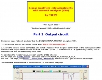 Linear amplifiers cold adjustments with network analyser (VNA)
 -
 A synthesized 2.3 GHz Amateur Television (ATV) transmitter design, conceived by Ian G6TVJ, is presented, targeting broadcast-quality video performance on the 13cm band and extending up to 2.6 GHz. The core of the design utilizes a commercial Z-comm Voltage Controlled Oscillator (VCO) that tunes from 2.2-2.7 GHz, providing a +10 dBm output and simplifying RF alignment. This VCO's stability, originally intended for narrowband applications, readily accepts high-frequency video modulation, contributing to the transmitter's robust performance. The exciter stage, incorporating a Mini Circuits VNA 25 MMIC amplifier, boosts the signal to +16dBm, while a Plessey SP4982 prescaler divides the output frequency for the synthesizer. The synthesizer employs a Motorola MC145151 CMOS parallel IC, favored over the common Plessey SP5060 for its superior video modulation characteristics and ease of programming without microprocessors. This choice addresses issues like LF tilt and distorted field syncs often seen with SP5060 designs, particularly when operating through repeaters or over long distances. The MC145151 divides the signal further, enabling precise frequency stepping, with programming handled by EPROMs for channel selection and LED display. The loop filter network, critical for video integrity, was developed through experimentation to prevent the PLL from reacting to video modulation, ensuring a clean transmitted picture. The transmitter incorporates a Down East Microwave commercial power amplifier module, delivering approximately 1.6W output, driven by the exciter through a 3dB attenuator. Construction involves surface-mount SHF components on micro-strip lines etched onto double-sided fiberglass board, housed within a tinplate box. The design boasts no AC coupling in the video path, preserving low-frequency response, a common failing in other ATV transmitters. Performance tests with a 50Hz square wave revealed no LF distortion, and a calibrated "Pulse & Bar" signal showed a near 100% HF response, demonstrating its capability for high-quality ATV transmissions.
 -
 This web article details the construction of a 4-meter band coaxial dipole antenna, designed for operation between **70.000 MHz and 70.500 MHz**. The resource provides a bill of materials and step-by-step assembly instructions for a half-wave dipole constructed from _RG-58_ coaxial cable. The design specifies a direct 50 ohm feedpoint impedance, eliminating the need for an external matching network. Construction photographs illustrate the stripping and soldering processes for the coaxial cable elements, ensuring proper electrical connection and physical integrity. The article includes specific dimensions for the radiating elements, derived from calculations for the 70 MHz band. The project outlines the physical dimensions required for resonance at 70 MHz, with the outer braid forming one half and the inner conductor forming the other. The feedline connection is directly to the coaxial dipole's center, maintaining a 50 ohm characteristic impedance. While the article does not present SWR plots or VNA sweeps, it focuses on the mechanical construction and dimensional accuracy for achieving a functional 4-meter dipole. The design is intended for fixed station use, with no specific mention of polarization or height above ground, but implies a standard horizontal orientation for dipole operation. DXZone Focus: Web Article | 4m Coaxial Dipole | Construction Guide | 50 ohm Feed
 -
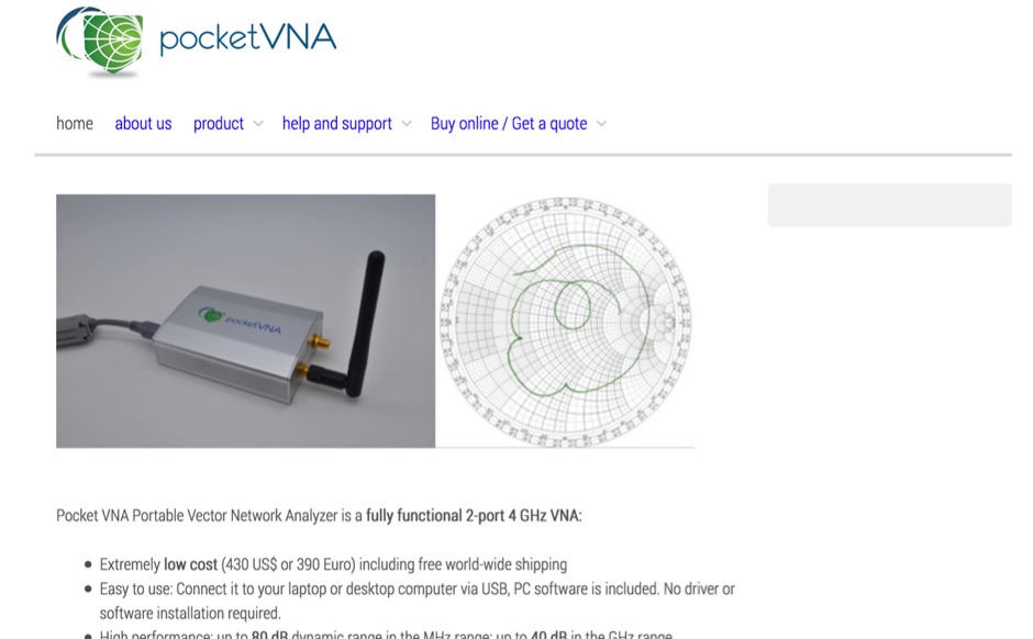 A 500 kHz to 5.5GHz 2-port vector network analyzer designed for use with any Linux, Windows or MacOS computer. High performance: up to 80 dB dynamic range in the MHz range; up to 40 dB in the GHz range
 -
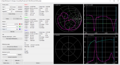
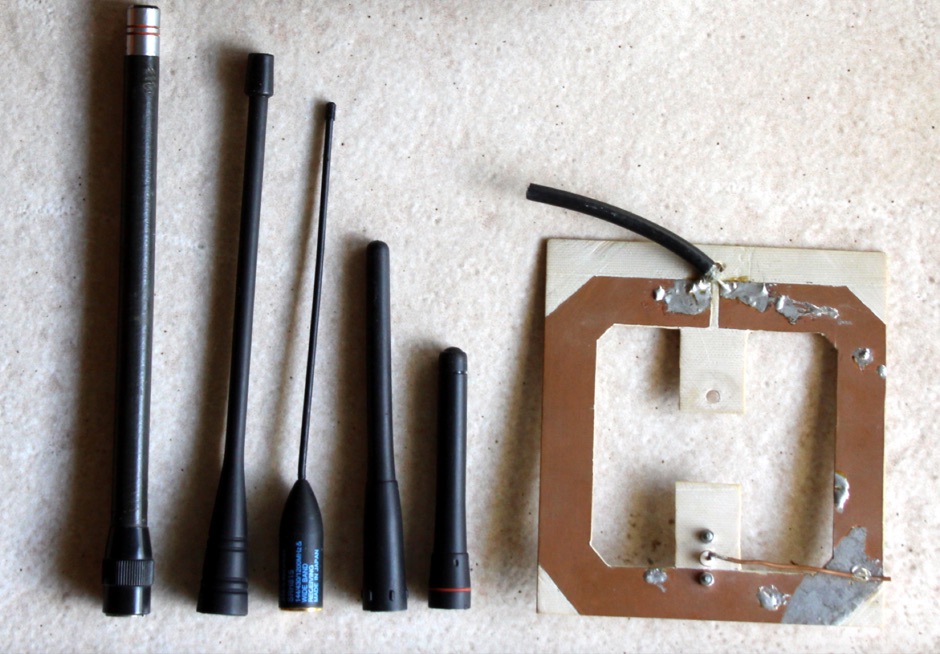 In this article the author analyze six different type of VHF handheld antennas and as result of his self training on his new vector network analyzer published this interesting report
 -
 This software connects to a NanoVNA and extracts the data for display on a computer, and for saving to Touchstone files.
 -
 Internal Bluetooth interface for miniVNA, Bluetooth connection to the PC allow Full cordless operation with ao external components
 -
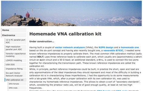 A calibration kit useful when you need known reference impedances to properly calibrate your vector network analyzers.
 -
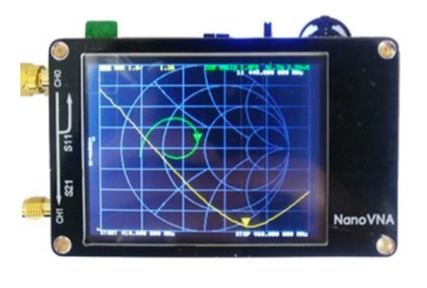
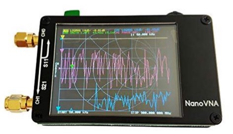 The NanoVNA is a very compact handheld Vector Network Analyzer. The NanoVNA is tiny and portable analyzer, and it offers a high performance capabilities with an embedded lcd display.
 -
 Enables Android users to operate various _miniVNA_ antenna analyzers via Bluetooth, USB, or Wi-Fi, providing a portable solution for RF measurements. The application supports full control over data acquisition, offering features like custom frequency range selection from 1 KHz to the VNA's full range, and automatic screen adaptation for diverse Android device resolutions. It facilitates intuitive, wizard-based calibration for both reflection and transmission modes, saving calibration data for different VNA types (Standard, Pro, Pro with Extender) to avoid repeated procedures. The software displays critical parameters such as SWR, |Z|, Return Loss, Phase, Rs, and |Xs| on 2-axis graphs or Smith charts, with multi-touch gestures for zoom and frequency shift. It includes a frequency generator mode with independent channels and attenuator control for the miniVNA Pro, along with a sweeper function. The cable data mode automatically calculates phase and loss, measures cable length from less than 1 meter to hundreds of meters, and includes a table of common coax cable velocity factors. An experimental X-tal mode measures resonance frequency, Rs, and Q. Data export options include CSV, ZPLOT, and S1P formats, with CSV import capability. The application also features an SM6ENG Audio mode for SWR tuning without visual reference and provides a miniVNA battery voltage indicator. It supports a wide frequency range, with the miniVNA Extender extending coverage up to **1500 MHz**. The application is compatible with Android version 2.2 and later, tested on devices like the _Galaxy TAB 7.7 P6800_.
 -
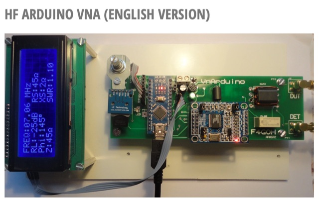 An home made VNA made with Arduino Nano. This project features an LCD display 4x20 works from 1 MHz to 60MHz, can use bluetooth connection with Blue VNA android app.
 -
 NanoVNA based on edy555, use the odd harmonic extension of si5351 to support the measurement frequency up to 900MHz. GitHub repository.
 -
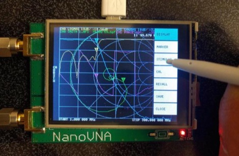 Very Tiny Palmtop Vector Network Analyzer by edy555. This is the original GitHub firmware repository implementing the standard 50KHz to 300MHz model
 -
 Notes on installing the miniVNA PRO software, making a calibration standard, a trap tuning loop.
 -
 There are quite a few recipes for building a suitable transformer for an end fed half wave antenna (EFHW), but I was never sure I really understood the main principles. So, I wound a bunch of transformers, made measurements on them using my NanoVNA, learned how to get what I really wanted out of the VNA measurements, and in the process discovered how to build better transformers and be able to predict what they will do
 -
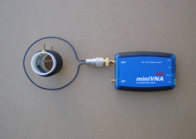
 The mini Radio Solutions miniVNA PRO is the only affordable vector network analyser (VNA) I know of that offers remote wireless operation. This is very interesting because it allows to measure the input impedance of HF antennas installed at height without having to deal with coax cable lengths, baluns nor common mode suppression chokes. However, to render the miniVNA PRO truly field proof, it requires a number of significant modifications.
 -
 Homebrew a 9:1 transformer and measurement for testing purposes with a miniVNA
 -
 The 1/4 wavelength vertical antenna project, initially designed for 20 meters, has evolved into a versatile portable solution covering 10 through 60 meters. K0BXB details its construction, emphasizing a bottom-loaded design with a tapped loading coil and four 10-foot counterpoise wires. The author shares personal experiences and field results, including **18 QSOs** during a park activation on 17m and 30m with 10 watts, and a **2,435-mile** contact with a contest station in Bonaire on 20m using 5 watts. Comparisons are drawn to commercial offerings like the _Wolf River Coils TIA_ and _QRPGuys Triband Vertical_, highlighting the DIY antenna's small footprint, light weight, and ease of tuning for POTA activations. The resource includes insights into using test equipment such as the _NanoVNA_ for SWR optimization and discusses various radiator lengths, from 17-foot wire to a 102-inch whip, demonstrating adaptability for different portable setups. Construction tips cover coil winding, tap placement, and connecting feedlines and radials using common components.
 -
 This project details the development of a modular direct conversion (DC) receiver designed for experimental flexibility in amateur radio and HF signal listening. The mainframe integrates a diplexer, DBM, and AF amplifier, supporting interchangeable local oscillator and antenna filtering setups. A tunable passive HF preselector complements QRP Labs bandpass filters for enhanced signal reception. Utilizing a NanoVNA for precise tuning, the receiver achieves improved signal-to-noise ratios across amateur and non-amateur bands, making it a versatile platform for further RF experimentation.
 -
 This report details a modification of a Diamond V2000 antenna, replacing its original two 0.50 m radials with two 1.55 m radials. Initial M5-threaded rods failed to fit; the housing required M6 threads. Custom radials were made using 8 mm OD aluminium tubing and M6-threaded stainless steel ends, secured with nuts machined to 9 mm. SWR issues on 6 m (>2:1) were largely due to a poor counterpoise connection, resolved during reassembly. NanoVNA measurements showed no adverse effects on 2 m or 70 cm. The final setup retains the two 1.55 m radials and original counterpoise. Other operators reported SWR degradation with similar mods—sometimes fixed by adding capacitance—but this was not observed here.