Search results
Query: element 9
Links: 515 | Categories: 3
-
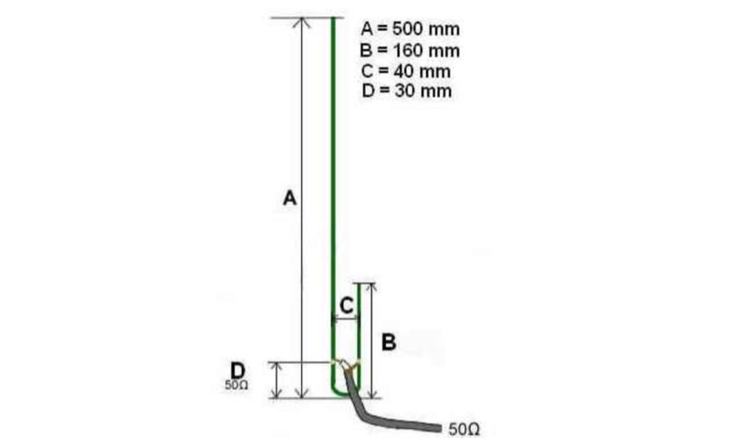
 The 2m 7 element Yagi antenna is a perfect beam antenna with 11dB gain and a front-to-back ratio of 20-25 dB. It has seven elements and requires a matching network built of 3/8" aluminum tubing and RG-8 cable. The gamma tube is adjusted to provide the best fit, and the gamma-driven element feeding clamp is tightened. If the beam is vertical, a non-conducting mast is utilized to prevent detuning and skewing of the radiation pattern. For optimal VHF operating, the antenna is installed at a height of 30 feet or higher.
 -
 Operating on the 60m band requires specialized antennas, and the 2 Element HB9CV, also known as the _ZL special_, excels in this domain. With a gain of **7.3 dBi** when phased at a 162-degree shift, it rivals traditional 3-element Yagi antennas, making it a solid option for enhancing 60m operations. The construction process is thoroughly detailed, providing insights into its performance and practical applications. Real-world comparisons demonstrate that the HB9CV antenna outperforms long Beverage antennas by an average of **5.5 dB** in reception, showcasing its effectiveness in various conditions. Insights from Mr. Cebik's analysis further validate its design, confirming its capability to maximize communication on the 60m band.
 -
 Guide to constructing an effective antenna for 50MHz. Inspired by a design from Martin DK7ZB, the article emphasizes the importance of precise measurements and quality materials. With a 2.20m boom and careful assembly, the antenna promises excellent performance, resilience, and cost-effectiveness, making it ideal for six meter band operations.
 -
 This paper presents an 80 meter wire 3-element beam antenna in an inverted-V configuration, designed for limited-height towers. Using EZNEC modeling, the antenna features a central parasitic reflector and two switchable driven elements at each end, enabling NE/SW coverage without moving parts or networks. Element lengths are optimized for SSB (3.8 MHz) and CW (3.5 MHz) operation, with a 50 Ω feed and rope-supported boom. The design delivers high gain, effective takeoff angles, and excellent reception, confirmed in real-world DX contest operation. Its simplicity, reliability, and ease of construction make it ideal for operators seeking performance without complex matching systems.
 -
 This paper by Leif Asbrink (SM 5 BSZ) presents a practical approach to designing very high gain Yagi antennas, focusing on the "brute force" optimization method. The method, described in a previous article, ensures convergence independent of initial guesses. The paper provides detailed tables of element lengths and positions for Yagi antennas optimized for 144.1 MHz with a 50-ohm feed point impedance, aiming for minimal losses and high accuracy in comparisons.
 -
 YAGio 1.01 is a Windows-based software for designing DL6WU long Yagi antennas on VHF and UHF frequencies. It supports Windows 2000, XP, Vista, 7, and likely 8. Using keyboard commands, users input specifications such as frequency, gain, and element diameters, and YAGio generates the design. You can download latest Yagio version from this page. Results can be saved in YIO, NEC, YAG, MMA, and YC6 formats, or printed directly.
 -
 VE1ZAC's analysis details the performance of **MFJ927** and **SGC239** autotuners with portable HF vertical antennas, specifically comparing 31 ft and 43 ft configurations. The resource originated from challenges encountered during a Maritime QSO Party roving operation, necessitating a lightweight and easily deployable antenna system. Target bands for the contest included 80, 40, 20, 15, and 10 meters, with a maximum power handling of 100 W CW. The author utilized a 30-foot carbon fiber push-up pole to support a vertical wire element, noting its 2 lb weight and reliability. EZNEC modeling was employed to predict performance, showing favorable results for a 30-foot vertical with elevated radials, particularly on 40 and 20 meters. Feedpoint impedance measurements, taken with an AIM4170C, are presented for various HF bands, both with and without a 41-foot RG6 stub designed to reduce reactance on 80 and 20 meters. The stub significantly improved matching on these bands, easing the tuner's workload. Operational tests revealed issues with the MFJ927's reliability during contest setup, leading to reliance on the K3's internal tuner. The SGC239, tested post-contest, performed flawlessly. A detailed side-by-side comparison covers mechanical aspects, connection options, power bias, impedance range, board quality, and documentation. Modifications to the MFJ927, including a new aluminum case, white paint for heat reduction, and upgraded impedance-measuring resistors, are also described.
 -
 145 MHz is the target frequency for this 2-meter Skeleton Slot Yagi Stack antenna project. The design focuses on feeding two stacked Yagi antennas using a skeleton slot radiator, which is a unique approach for VHF enthusiasts. The project details the construction process, including the loop tapered matching section for impedance matching, ensuring optimal performance. The use of specific components like the EH789 element holder and MB456 main mast bracket is highlighted, providing clarity on the assembly process. The construction utilizes 20x20 box aluminum bar for durability and precision. Key dimensions, such as the element length (ER-ED4) and main boom spacing (MM123), are meticulously outlined. This attention to detail aids in replicating the antenna design accurately. The downloadable PDF offers comprehensive instructions, making it accessible for amateur radio operators interested in VHF antenna construction. This project is particularly beneficial for those looking to optimize their 2-meter band operations. The inclusion of a skeleton slot radiator and loop tapered matching section demonstrates advanced techniques in antenna design, catering to both intermediate and advanced builders.
 -
 This project describes a high-performance EME antenna array consisting of two home-designed 9-element Yagis, each about 2.5 wavelengths long, combined into a 25-ohm system and matched to 100 ohms using 9/4λ sections of 50-ohm coax. The array supports rotatable polarity from 0° to 180°, allowing both horizontal and vertical polarization to optimize moonbounce performance under varying conditions. Despite operating for years without a balun—something another designer called “disastrousâ€â€”the system has delivered strong results, including copying very weak DX such as VK3KH at about -25 dB with only 120 W (around 2 kW ERP). The builder continues to refine the mechanics, having installed new gear motors and an upgraded follow-up control system in 2011.
 -
 Ham Exam provides adaptive practice tests that adjust difficulty based on your performance. The site offers all current question pools and calculates your probability of passing the actual exam based on your practice results. It includes detailed explanations for each answer and tracks your progress across specific subelements of the exam. The clean, distraction-free interface makes it easy to focus on studying, and no registration is required to use the basic features.
 -
 This online project documentation details the construction of a hands-free microphone interface unit designed for _mobile_ amateur radio operation. The curriculum covers the integration of electret microphone elements with amateur radio transceivers, specifically addressing **VHF** band communication. It outlines the circuitry for a switch box that provides an interface between various radio models and microphone types. The guide specifies the inclusion of a **1750 Hz** tone-burst generator for accessing amateur radio repeaters, an operational protocol for many VHF systems. Design considerations include the reduction of ambient vehicle noise through an adjustable audio input level control. The project provides schematics and wiring diagrams for connecting the interface unit to specific amateur radio transceivers, including the Yaesu FT-817. It addresses the selection and adaptation of readily available electret microphone and earpiece assemblies, initially sourced from mobile phone accessories, and later from dedicated headset units. The design incorporates a control mechanism for radio functions, enabling hands-free operation during _mobile_ excursions. Circuit details cover power supply considerations for the electret microphone and signal routing for both transmit audio and received audio monitoring. The documentation specifies component selection for the switch box, ensuring compatibility with common amateur radio microphone input impedances and output levels. This includes considerations for PTT line switching and audio path isolation. DXZone Focus: Online Project Documentation | Hands-Free Mobile Microphone Interface | Electret Microphone Integration | 1750 Hz Tone-Burst Generation
 -
 Demonstrates the construction of an active loop converter specifically designed for the Low Frequency (LF) bands, addressing common localized noise interference in LF reception. The design integrates a sharply tuned circuit and a tuned loop antenna, utilizing the loop as the sole tuned inductive element. By applying positive feedback, the converter significantly increases the loop's effective Q, achieving factors between 1000 and 2000, which sharpens tuning and reduces noise. The circuit employs an _NE602_ mixer stage, feeding its output to an HF receiver, with a crystal-locked local oscillator at 4 MHz. A 20-turn, 0.8-meter square loop antenna with 500 uH inductance is detailed, connected via 2 meters of figure 8 flex cable. The converter offers three selectable frequency bands: 195-490 kHz, 150-220 kHz (including the New Zealand amateur band), and 128-160 kHz (covering the European amateur band). Performance measurements indicate an effective 3dB bandwidth of approximately 100 to 200 hertz at 200 kHz. The article provides insights into component selection, including an _LF353_ op-amp and a trifilar wound transformer on a ferrite core. Sensitivity figures are presented, showing 7.5 uV of converted output per 1 uV/meter signal strength into a 50-ohm load, or 37.5 uV into an _FRG7_ receiver, highlighting its capability to extract weak signals from noise.
 -
 The UHF J-Pole antenna described here utilizes an aluminum angle bar and 4mm galvanized threaded rod for its construction, with dimensions based on a previously published design. Assembly involves drilling the angle bar, securing threaded rod sections with nuts, and connecting the coaxial cable via cable lugs, ensuring the braid connects to the shorter element. ROS adjustment is achieved by manipulating nuts approximately **30mm** from the angle bar, allowing for fine-tuning of the impedance match. Once optimal tuning is established, _super glue_ is applied to seal the coaxial cable ends and protect the threaded rod cuts from corrosion, enhancing durability. This project emphasizes rapid realization with common hardware, providing a practical solution for radio amateurs seeking a simple yet effective antenna for the 70cm band.
 -
 The 4m Slim Jim antenna project provides a construction guide for a low-cost, high-performance aerial designed specifically for the 70 MHz FM band. This design achieves a 1:1 SWR across the 4m FM band with straightforward adjustment of the feed point, utilizing RG-58 coax. Its low angle of radiation contributes to effective signal propagation. Construction involves using plastic knitting needles as spreaders and a telescopic fishing pole for support, with components secured using two-part epoxy. Annealed bare single-core copper wire forms the radiating element. The setup process includes raising the antenna at least 3 meters above ground for tuning, adjusting the RG-58 feed point for optimal SWR, and then soldering connections. Waterproofing is achieved with yacht varnish. The design emphasizes low wind resistance for durability, making it suitable for exposed outdoor installations. A PDF construction diagram is available to supplement the written instructions.
 -
 The aprs.fi Android application offers immediate, real-time access to APRS position information, weather reports, and telemetry graphs, allowing users to zoom and browse stations globally without delay. It includes features like callsign and address search with history, multi-station tracking, and map filtering for elements such as weather stations and AIS targets. The app also supports KML and GeoJSON overlay files for enhanced map visualization. Users can beacon their position directly to aprs.fi or connect wirelessly to a Bluetooth, BLE, WiFi, or USB-attached TNC for receiving and transmitting position beacons without an internet connection. The application runs on the robust and fast aprs.fi database, providing _Dark Mode_ support for improved ergonomics in low-light conditions and high-resolution graphics for modern displays, including the full APRS symbol set. While the core application is a one-time purchase, some advanced functionalities, such as APRS text messaging, a high-performance software DSP modem, and _APRS-IS_ beaconing with up to **10 callsign profiles**, require an additional "Extra Features" subscription. This subscription also unlocks RX iGate functionality and extended time ranges for map and graph views, expanding its utility for serious APRS operators.