Search results
Query: 160 m l antenna
Links: 215 | Categories: 3
-
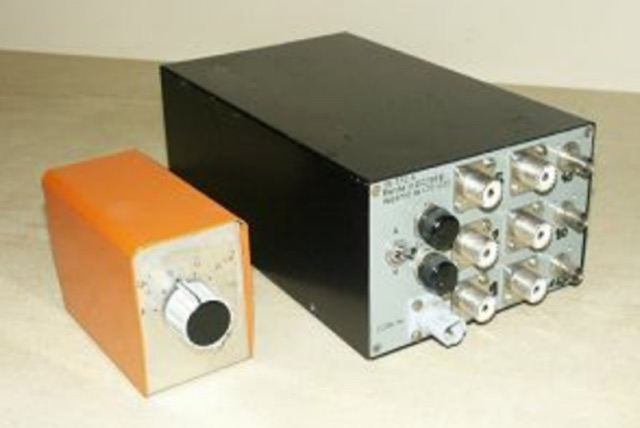 Sharing beverage antennas with this switch boxes is possible. This article describes a 6-position remote antenna switch for Beverage antennas on 3 bands (160m, 80m, 40m). It allows selecting one of 6 antennas for each band without affecting other receivers. The system uses a control box with a rotary switch and a separate splitting box with bandpass filters for each band.
 -
 If you have a small lot and want on 160 meters this is our version of the antenna by K5CBL Troy
 -
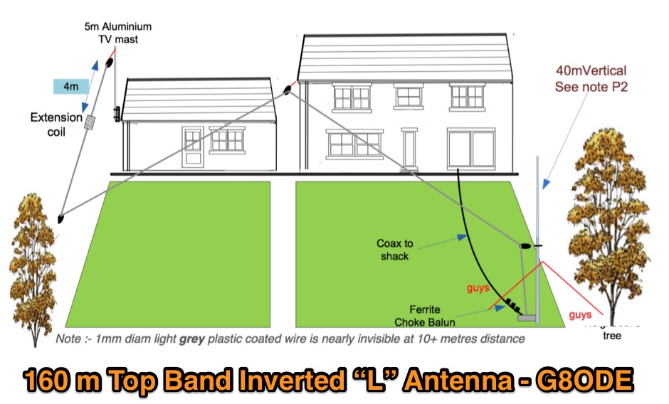 G8ODE 160 m Top Band Inverted L Antenna made of 33m horizontal wire in the garden
 -
 Based on a W4TWW project and modified by KN4LF
 -
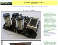 Homebrew balanced-L antenna tuner. Covers 160-10m. Designed specifically for balanced feedlines.
 -
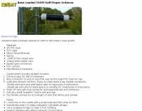 If you want an antenna resonoant on the 160 meters band this is a possible solution, but of course, need space.
 -
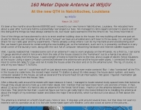 Pictures of the 160 meters dipole antenna at W5JGV
 -
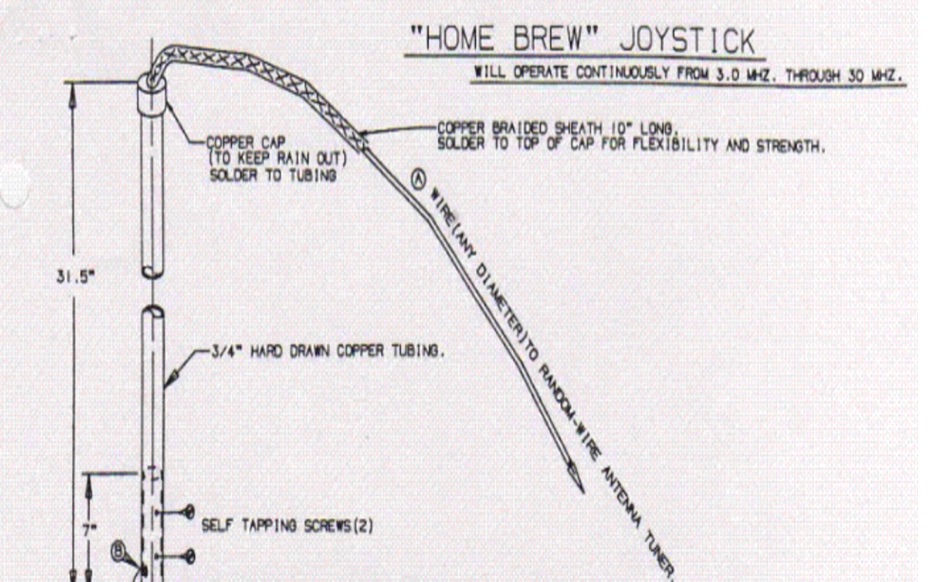 The Joystick antenna was used many years ago as an all band vertical HF antenna under restricted space situations that would cover from 80 meters thru 10 meters with a tuner and was a great commercial success Some hams even had success with it on 160 meters.
 -
 The basic antenna is a vertical monopole, using elevated radials to complete the ground plane by k5oe
 -
 The total length of the inverted L is 240 feet, which is 7/16th of a wave length long. It has a 92 foot horizontal linear load section 1 foot above ground that terminates into a home-brewed parallel network tuner by KN4LF
 -
 This high antenna require a large ground composed by 40 radials. It's not very handy expecially in windy situations but is very powerfull in pile-ups. In italian
 -
 A 3.42-meter (11-foot 2-inch) extended-length mobile antenna project is presented, detailing its evolution from an initial 1.65-meter design. W5JGV shares his journey in optimizing mobile HF performance, noting that increasing the top whip length significantly improved radiation efficiency by reducing coil losses and allowing for larger wire gauges. The article includes a comparative table illustrating substantial gain increases, with the 3.42-meter version showing up to 40.6% efficiency on 21.2 MHz compared to a half-wave dipole. Construction details are thoroughly documented, from the use of hard-wall copper pipe for mast sections to the fabrication of custom loading coils. The author explains the necessity of an insulating brace for self-supporting coils and details a unique rotational alignment mechanism for off-center mounted coils to prevent snagging on overhead obstructions. He also describes a "Z" winding technique for 75-meter and 160-meter coils, which minimizes copper losses and manages dielectric losses. The resource provides specific loading coil data, including wire gauge, number of turns, coil length, and inductance values for bands from 18 MHz down to 2 MHz. It emphasizes that these coils may require fine-tuning based on individual vehicle and whip configurations, suggesting an antenna tuner for optimal mobile station operation across multiple HF bands.
 -
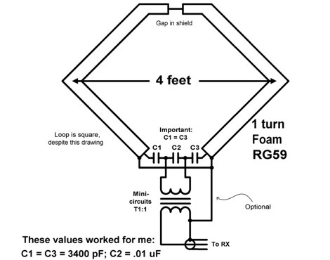
 A really simple receiving antenna for 80 and 160 meter dxing by WA2WVL
 -
-
 Makers of motorized antennas covering 6 to 160 meters
 -
 A potpourri of 160-Meter vertical antennas and modeling issues, inverted-L, 3-element parasitic array, 1/4-wavelength monopole
 -
 KN4LF article about a 1/4 wave fan inverted L antenna for 80 and 160 meters band
 -
 Bill Orr W6SAI ham radio techniques. Improving ground connection, computer analysis of the antenna, modelling sample antennas pdf file
 -
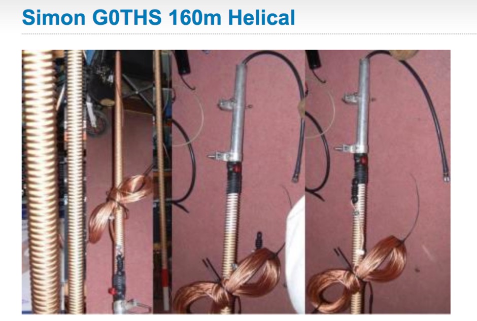
-

-
-
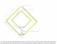
 The 6 Band Inverted L Antenna MK3 is a versatile multiband antenna designed for amateur radio operators. This antenna covers 160m, 80m, 40m, 20m, 15m, and 10m bands, making it suitable for a wide range of HF communications. The design is based on a W3DZZ configuration, incorporating traps for optimal performance. The MK3 version features a sturdy 5/8th CB mast, replacing the original timber mast, which enhances durability against harsh weather conditions. The antenna's construction allows for effective operation, particularly on the 40m band, where it has been successfully used to contact distant locations including ZL, VK, and Antarctica. Constructing this antenna requires careful attention to detail, especially regarding the radials and grounding. The traps resonate at specific frequencies, and additional resources are available for building coaxial traps. The antenna is designed to work efficiently without an ATU on the lower bands, while higher bands may require tuning. This project is ideal for both beginner and intermediate operators looking to enhance their station with a reliable multiband antenna.
 -
-
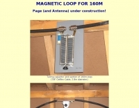 Pictures and calculated values for this home made magnetic loop antenna for the 160 meters band by HB9MTN
 -

-
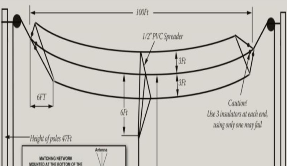 160m T Antenna broadcast design by Guglielmo Marconi has been built and is used by Jim NN4AA on 160m. Article by G7LRR
 -
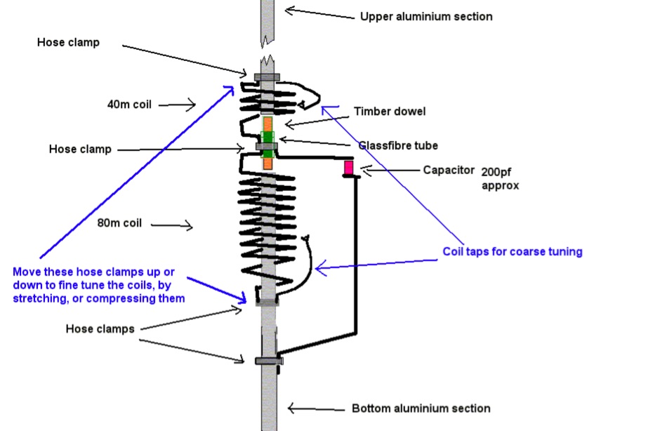 Article on the HF dual band antenna with construction details and how to add 160 meters to the HF2V
 -
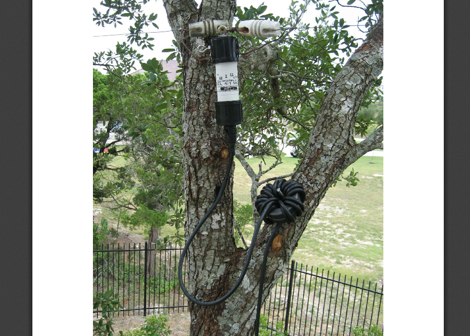 An easy to build single wire antenna for 160 and 80 meters with a better than 2 to 1 swr across the 80 meter band by K5GP
 -
 An article on TX and RX antennae for the low bands 80 and 160m by EI7BA
 -
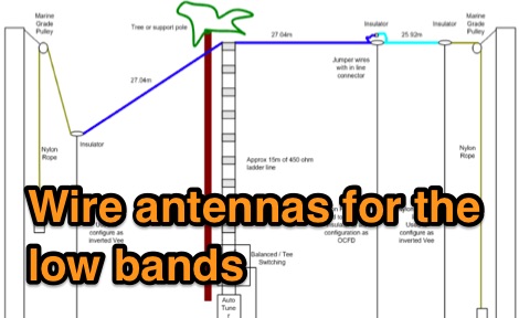 Experiments by G8JNJ on wire antennas for low bands. Based on these tests, conclude that for multiband (160 to 6m) operation, in a restricted area it is very difficult to beat a G5RV, especially the ZS6BK version.
 -
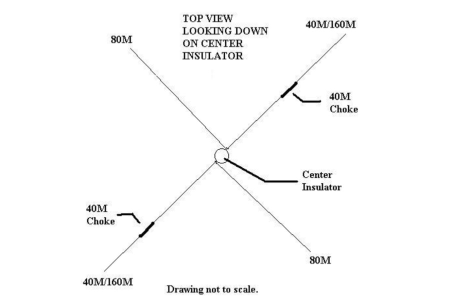 How to build a multi-band dipole antenna with a single coax feed. Instructions for a 160M antenna that will fit in the space that a 75M dipole will with almost as good of results as a full size 160M dipole.
 -
 VE7CA experiments on 160 meters band antennas, looking for better performances on reception.
 -
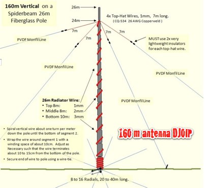 A vertical antenna for the top band, made with a 26m fiberglass spiderpole by DJ0IP
 -
 Demonstrates a practical modification to convert a standard G5RV antenna into a _160-RV_ for effective operation on the 160-meter band. This project addresses the challenge of achieving Top Band resonance with a common multi-band wire antenna, providing a solution for hams with limited space or resources for dedicated 160m antennas. The design utilizes a specific length of 450-ohm ladder line and a 1:1 current balun, acting as a matching section to bring the G5RV's impedance into a usable range for 1.8 MHz. The document includes a parts list, detailed construction steps, and tuning instructions, emphasizing the importance of precise measurements for the ladder line and coaxial cable sections. It also outlines the expected SWR characteristics and power handling capabilities, making it suitable for QRO operation up to 1.5 kW. The _AD1B_ design offers a straightforward approach for extending the utility of an existing G5RV.
 -
 A ranking of receiving antennas based on noise being evenly distributed in all directions. These rankings are most accurate in the frequency range of AM broadcast, 160 or 80 meter bands
 -
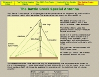 3 Band vertical Marconi-antenna for the bands 40, 80, 160 meters with a ground net of wires as radials.
 -

-
 An easy to build single wire antenna for 160 and 80 meters with a better than 2 to 1 swr across the 80 meter band
 -
 The Q-signal **QRP** signifies a request to reduce power, and in amateur radio, it defines operating with 5 watts or less for CW and 10 watts or less for SSB. This article addresses common inquiries from new hams regarding the practice, its benefits, and implementation methods. It explains how a 5-watt QRP signal, compared to a 100-watt signal, typically results in only a 13dB drop in signal strength, equating to about two S-units, still providing solid copy under most conditions. Hams choose QRP for various reasons, including seeking a greater challenge in DXing or contesting, reducing band interference, or enabling portable field operations with lightweight, battery-efficient equipment. A modern single-band CW transceiver, key, and antenna can fit into a pocket, offering receiver performance comparable to commercial rigs and extended operation on a small battery. This portability facilitates operations in remote locations where higher-power setups are impractical. Operating QRP can involve simply reducing power on an existing commercial HF rig or building a dedicated QRP transceiver from a kit, such as the **Wilderness Radio SST** with its 2-watt output and 15mA receive current draw. While SSB is viable, CW remains the most popular and efficient mode for QRP due to its superior signal-to-noise ratio. The article lists common QRP calling frequencies across 160m through 10m bands for both CW and SSB, and highlights organizations like QRP ARCI and NorCal that support the QRP community.
 -
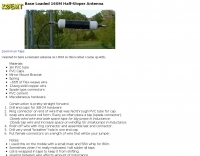
 M0VEY shares insights into constructing a 160-meter mobile DX aerial, detailing the process of sourcing materials and assembly. The project began with a goal to avoid a £50 commercial antenna, instead utilizing a £10 reel of _enamelled copper wire_ and salvaged components like alloy tent poles and plastic water pipe. A friend fabricated a custom stainless steel tube for mounting, featuring a 3/8” thread for a mag-mount, enabling secure vehicle attachment. The aerial's design incorporates four alloy tubes, one plastic tube, and a five-foot whip, engineered to split into two pieces for convenient storage. The loading coil, wound with approximately 115 feet of 0.75mm wire onto a plastic former, was then sealed with blue heat shrink. M0VEY reports successful operation, making contacts across the UK and Europe, with the aerial standing about ten feet tall for local nets at 1.972 MHz and taller for the DX window around 1.845 MHz. Future plans include a base-loaded 160m aerial and an 80m version, leveraging components from the existing _160m DX Mobile Aerial_ to maintain a similar overall size with a smaller coil.
 -
 A quick vertical for 160 meters portable use
 -
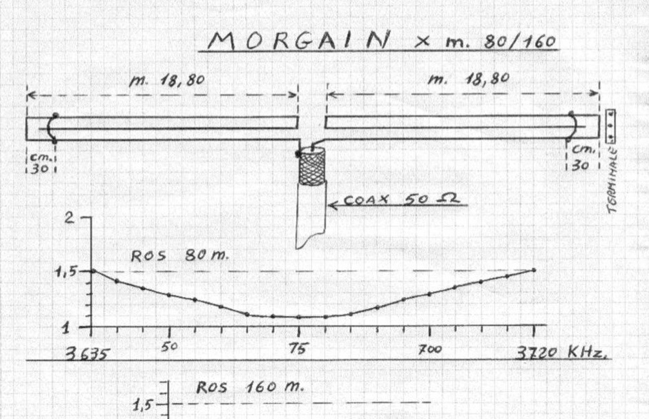 A 37.6-meter Morgain antenna design provides dual-band operation on 80 and 160 meters without traps. The antenna uses 1.5 mm² stranded copper wire with vinyl insulation, commonly found as domestic electrical wire. Tuning involves adjusting lateral jumper wires for the 80-meter band, with initial positions 30 cm from the arm ends, yielding 3635–3715 kHz resonance with SWR below 1.5:1. For 160 meters, a straight wire length of 18.80 meters per arm is critical, achieving 1840–1850 kHz resonance with SWR below 1.1:1. The Morgain antenna exhibits a 50-ohm feed-point impedance, allowing direct connection of 50-ohm coaxial cable like RG-8X, which handles approximately 500 watts. Spacers and the central plate are constructed from 1 mm thick green fiberglass laminate, with spacers measuring 11 cm and installed every 1.90 meters. The central plate is 11 × 11 cm, designed to secure the coaxial cable mechanically. End supports utilize 3–6 mm thick bakelite terminal spacers, tensioned with nylon ropes.
 -
-
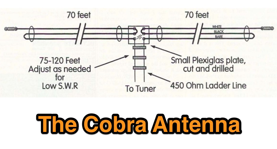 A folded wire antenna for 160 meters as appeared on 73 amateur radio magazine june 1997
 -
 A 90-foot vertical antenna constructed from **aluminum irrigation tubing** is detailed, focusing on its innovative raising and lowering mechanism. The resource describes a **45-foot ginpole** system, allowing a single operator to erect or lower the antenna in minutes. It covers the mechanical design, including the pivot base, insulated joints for the tubing sections, and guy wire attachment points. The antenna consists of two 30-foot sections of 4-inch tubing and one 30-foot section of 2-inch tubing, stacked with the smaller diameter at the top. The electrical design incorporates PVC "condulet" boxes at the 30-foot and 60-foot points, housing relays to change the effective height for multi-band operation on 160, 80, 40, and 30 meters. Ferrite rod inductive chokes are used for DC control and to tune out gap capacitance. The antenna is fed with 1000 feet of open wire line, connected to a matching transformer comprising stacked toroids and a coaxial/toroidal balun. Grounding is achieved with a 3x3 foot grid of 16-gauge tinned copper wires with soldered crossovers.
 -
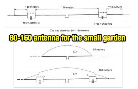 An cheap, easy to construct and not too visible antenna for the low bands
 -
 This resource details the conversion of an 80m elevated vertical antenna to include 160m operation, focusing on a relay-switched design over a trap-based approach. It presents specific feedpoint impedance values, such as **32 ohms** for 80m and **14 ohms** for 160m, and discusses the challenges of SWR drift encountered with the prior trap system during RTTY contesting. The article thoroughly explains the design choices for elevated radials, referencing _N6LF QEX data_ to debunk common myths regarding radial length and height, demonstrating that non-resonant radials can offer superior current uniformity. The construction section provides practical insights into building the vertical, including guying strategies, material selection from scrap pipe, and weatherproofing the relay assembly. It highlights the use of a common mode choke for the relay switching line, measuring approximately 5K ohms on both 160m and 80m, and details the L/C matching network's role in achieving a 50-ohm match at the end of a 300-foot RG-11 run. The author describes a precise VNA-based radial trimming procedure, achieving resonant values within a 3 KHz range. The content emphasizes the practical application of theoretical antenna principles, particularly concerning the interaction between the vertical element, cap hats, and the matching network. It offers a candid assessment of component selection, such as using junkbox parts and acknowledging the need for future upgrades to static drain resistors. The article serves as a comprehensive case study for advanced antenna builders tackling multi-band vertical designs.
 -
 This vertical antenna consist of a 18 meters telescopic pole and allow operations from 160 to 30 meters band, project by Daniel Zimmerman N3OX
 -
 Anyone attempting to work DX on Top-Band 160 Meters, soon learns of the need for a good receiving antenna. This is a 160 meter 8 element receiving array.
 -
 This is a project by F5IMV devided to build a balanced Z-match, capable of matching an unbalanced 50 ohm transmitter output into an antenna fed by balanced feeders.