Search results
Query: 40m 20m
Links: 63 | Categories: 0
-
 This article documents the author's journey in building, modifying, and testing a DIY short vertical antenna for 40, 30, and 20 meters, with potential 80m capability. Initially inspired by Parks On The Air (POTA), the author explores pedestrian mobile operation and details various experiments to enhance antenna performance. The piece highlights challenges, SWR tuning, portability, and practical results, emphasizing a balance between efficiency and size. Ultimately, it showcases the adaptability of DIY antennas for portable ham radio applications.
 -
 The author reflects on expanding their antenna for 80m coverage during lockdown. They extend the End Fed Half Wave (EFHW) using a Spiderbeam pole and "cheating" by dog-legging across their garden. Despite challenges, they achieve coverage for multiple bands with minimal cost. Practical Wireless features EFHW antennas, including a pre-made 20m EFHW extended for 40m.
 -
 How to Design and Build a Field Expedient End-Fed Half-Wave Antenna for 20m, 40m and 80m. This Shorty 80m EFHW comprises a 49:1 autotransformer (to match the very high impedance at the end of a half-wave wire), a half-wavelength wire for 40m (also a quarter-wavelength for 80m), a loading coil and a short tail wire. The coil and the short tail wire (about 6 feet) make up the other quarter wave on 80m.
 -
 Schemaric diagram for a 80m, 40m, 30m, 20m EFHW Antenna Antenna Tuner. The tuner has been designed for an antenna length of 41m and the counterpoise 7.5m.
 -
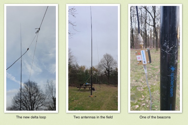 Intrigued by a German OM positive experience with a 20m delta loop, the author replicated the design, noting its favorable 50-ohm impedance compared to their 40m version. Testing against a vertical EFHW, the delta loop excelled within EU but lagged at longer distances. Despite needing more testing, the user leaned towards the EFHW for its overall performance and practicality.
 -
 WB8LZR details the construction and initial field results of a multi-band vertical wire antenna, designed to complement his existing horizontal loop for improved DX on 80 meters. The antenna utilizes a 67-foot vertical wire, configured as a quarter-wave radiator on 80m, and employs a 1:1 current balun for RF isolation on 80m, 30m, and 17m. For bands like 40m, 20m, and 10m, where the wire acts as a half-wave or full-wave radiator, an additional impedance transforming _unun_ is integrated to manage the significantly higher feedpoint impedance and voltage. The author notes the vertical's performance as a receiving antenna, observing reduced noise compared to his main horizontal loop, particularly on 80m, and even hearing some long-path signals the loop missed. Initial QRP contacts, including a **1-watt** QSO with a _VP2 station_ on 30m, demonstrate its transmit capability. While the radial system is currently rudimentary, the project outlines practical considerations for multi-band vertical deployment and impedance matching.
 -
 This study details a reception comparison between vertical and horizontal active loop antennas, specifically two identical _Wellgood active loop antennas_, on various HF bands. The experiment, conducted in a densely populated QRM-prone area, monitored FT8 signals over a 24-hour period using two identical receivers. The methodology involved direct comparison of signal reception across the HF spectrum, aiming to identify performance differences based on antenna orientation. The results indicate that vertical loops demonstrated superior performance on higher bands (10m, 15m, 20m), while horizontal loops excelled on lower bands (30m, 40m, 160m), particularly for receiving long-distance (DX) signals. The horizontal loop's advantage on lower bands is attributed to potentially better low-angle performance and reduced sensitivity to man-made noise, yielding a **2-3 S-unit** improvement on 160m. The study provides practical insights for optimizing antenna placement in challenging urban environments, noting that the horizontal loop consistently showed a **10-15 dB** signal-to-noise ratio improvement on lower bands.
 -
 From March 2 to March 11, 2018, a Norwegian team operated as Z2LA from Zimbabwe, focusing on 160m through 10m bands using SSB and CW modes. The operation, described as "holiday style," aimed to provide contacts for DXers worldwide seeking a rare DXCC entity. Key equipment included a SUNSDR PRO II, an Elecraft KX3, and an Icom 706 MK2G as a spare radio, supported by two Juma 1000 amplifiers for robust signal output across the bands. Antenna systems were tailored for multi-band operation, featuring an Inv L for 160m and 80m, sloping dipoles for 30m/40m, and a _Hexbeam_ from SP7IDX Technology covering 20m to 10m. For improved reception, the team deployed a SAL 30, two reversible BEV antennas from remoteqth.com, and a BOG from K1FZ, enhancing their ability to hear weak signals. QSL information directs operators to Clublog for log search and M0OXO Charles for OQRS, explicitly requesting no bureau cards. The team comprised LA7THA Rune, LA7WCA Arne, and LA9VPA Thor, successfully making numerous contacts and contributing to the DX community's pursuit of _Zimbabwe_ as a DXCC entity.
 -
 The Butternut HF2V, originally a two-band vertical antenna for 80m and 40m, was enhanced by the user to include 30m and 20m bands for better digimode DX work during the solar minimum. The additions used components adapted from the HF6V and innovative methods for the 20m addition, either through a parallel vertical element or a lower-mounted independent element, minimizing band interaction. This modified four-band antenna now supports high power across popular HF bands using a single feedpoint.
 -
 PH0NO conducted field tests comparing a mobile antenna (DX-UHV) to an end-fed half-wave wire. Results on 20m showed the end-fed wire outperforming the mobile antenna, with a significant difference in signal strength. On 40m, the end-fed wire surpassed the mobile antenna in spots and reach. While the mobile antenna is more practical, the end-fed wire offers superior performance. Further testing is planned.
 -
 This **PDF report** documents a _maritime mobile_ DXpedition operating from the _Southern Ocean_ near Antarctica, detailing antenna deployment strategies on a sailing vessel. It addresses power management systems for remote operations and propagation characteristics specific to polar regions on **20m and 40m** bands. Operational strategies include managing high-density pileups using split frequency operation and maintaining signal integrity during periods of high aurora activity. Equipment considerations cover specific transceiver models like the Icom IC-7300, antenna types optimized for marine vessel installation, and battery power systems for extended periods without shore power. The resource also examines the use of satellite communication for real-time log uploads and QSL confirmation from remote locations, and discusses mitigating signal degradation from ice accumulation on antennas. DXZone Focus: PDF report | Maritime Mobile DXpedition | Polar Propagation | Split Frequency Operation
 -
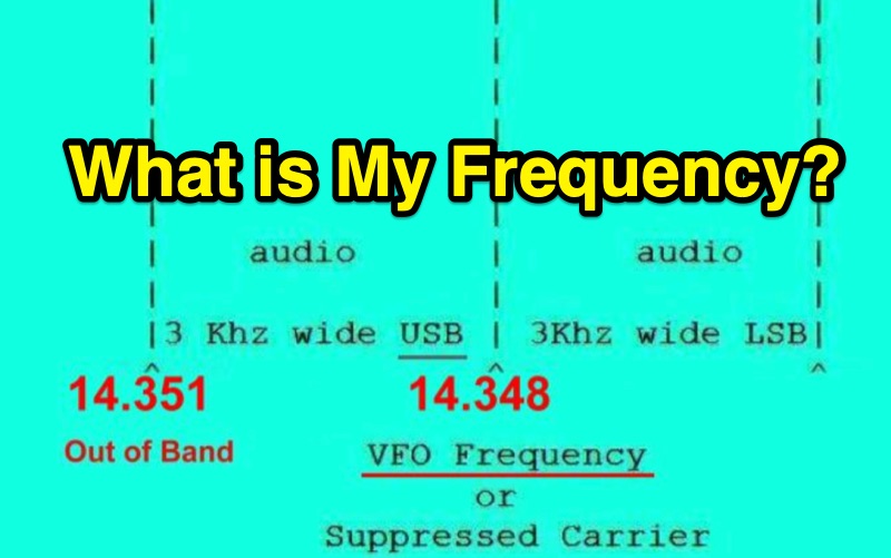 Single Sideband (SSB) operation requires careful attention to the relationship between a radio's displayed frequency (suppressed carrier) and the actual 3 kHz wide audio signal. This resource clarifies how Upper Sideband (USB) and Lower Sideband (LSB) signals occupy spectrum above or below the indicated frequency, respectively. It provides practical examples for General Class operators on the **20m** and **40m** bands, such as setting a VFO to 14.226 MHz for USB on 20m or 7.178 MHz for LSB on 40m, to maintain a safe margin from band edges. The resource emphasizes the critical importance of staying within allocated band limits to prevent out-of-band emissions, particularly when operating close to band edges. It includes relevant excerpts from **FCC Regulation Part 97**, specifically section 97.307, which details emission standards, necessary bandwidth, and spurious emission attenuation requirements. The text explains that unused sidebands are considered spurious emissions and notes that modern HF equipment typically exceeds the 43 dB spurious emission reduction standard, often achieving 60 dB or more.
 -
 Presents detailed expedition charts and statistics for the **XX9W** DXpedition, covering operating time, total QSOs, unique calls, and duplicate QSOs. The resource provides comprehensive band and mode breakdowns, including FT8, SSB, CW, and FM, across 80m, 40m, 30m, 20m, 17m, 15m, 12m, 10m, 6m, 2m, and 70cm. Users can access DXCC statistics by band and mode, daily QSO totals, and multiband QSO statistics. Continent-by-mode and continent-by-band breakdowns are also available, detailing activity from Africa, Asia, Europe, North America, Oceania, and South America. The platform also tracks the expedition's impact on user totals, showing new band, new mode, new band + new mode, new slot, and new DXCC contacts.