Search results
Query: Moxon
Links: 96 | Categories: 4
-
 The **2M Moxon antenna** design presented operates at 144 MHz, providing a compact, directional solution for VHF communications. Construction involves aluminum tubing for the elements, with specific dimensions for the driven element and reflector to achieve optimal performance. The design aims for a good front-to-back ratio and a relatively low SWR across the 2-meter band, making it suitable for portable or fixed station use where directivity is beneficial. Element lengths are critical for proper resonance and pattern. The driven element measures approximately 38.5 inches, while the reflector is slightly longer at 40.5 inches. Spacing between the elements is 12 inches, forming the characteristic Moxon rectangle. This configuration yields a gain of about 5.5 dBi and a front-to-back ratio exceeding 20 dB, which is advantageous for reducing interference from unwanted directions. Feedpoint impedance is close to 50 ohms, allowing direct connection to coaxial cable without complex matching networks. The antenna's lightweight structure, typically under 2 pounds, facilitates easy deployment and rotation, making it a practical choice for field operations or as a compact home station antenna.
 -
 The Moxon Beam, introduced by L. Moxon (G6XN), is a compact 2-element Yagi featuring a radiator and reflector with reduced dimensions, approximately 75% the size of a full-size beam. This design utilizes bent element ends for capacitive loading, which is superior to inductive loading with coils, resulting in greater bandwidth and lower losses. DK7ZB details that while the gain is slightly lower (0.5-0.7 dB) than a full-size beam, the _Moxon_ offers an exceptional front-to-back (F/B) ratio of 30 dB or more on its design frequency, surpassing other 2-element beams. The article provides specific dimensions for building wire _Moxon_ antennas for bands from 30m down to 10m, and also mentions a 2-m-Moxon. Construction guidance includes using fishing rods for lightweight spreaders and an aluminum tubing spider for support. The resource highlights the utility of _Moxgen_ by AC6LA, a freeware program that simplifies Moxon beam design and generates EZNEC output files for further analysis and tapering modifications. DK7ZB emphasizes that the design frequency should be set at approximately one-third from the band's beginning to optimize SWR performance, as SWR tends to rise more significantly below the design frequency. The bandwidth for SWR < 1.5 is noted as sufficient for ranges like 28.0-28.7 MHz and 21.0-21.45 MHz when constructed with aluminum tubes, though wire beams exhibit a narrower bandwidth.
 -
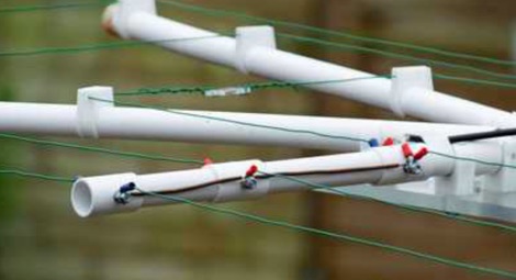 A PDF presentation of a home made moxon antenna for 50 MHz 70 MHz and 144 Mhz. The project is mainly out of surplus plastic Plumbing pipes and clips etc, and also details of how the dimensions were calculated.
 -
 The GW3YDX Super Moxon antenna design improves upon the standard Moxon Rectangle by incorporating additional directors in a rectangular configuration, yielding enhanced directivity and gain. For the 6m version, modeling with 4NEC2 and EZNEC+ indicated a 3dB gain increase and a 26.5dB front-to-back ratio, with VSWR below 1.5:1 between 50.0 and 50.3MHz when optimized for 50.1MHz. This design achieves a narrower -3dB power point beamwidth of 60° compared to the original Moxon's 80°, contributing to better QRM rejection. The boom length for the enhanced design is just under 2m, approximately double the original Moxon's, with no increase in wingspan. Construction details include tubing lengths for 6m, 4m, and 2m versions, with specific dimensions provided for elements A through M, measured to tubing centers. For instance, the 6m version uses a 2160mm element A and a 2140mm element H. The design maintains a 50-ohm feed impedance, with practical models showing VSWR plots consistent with simulations after minor adjustments to driven element lengths. The article also references Moxgen software for initial Moxon parameter calculation and NEC/EZNEC model generation. The 2m Super Moxon version measures approximately 30" x 25", demonstrating the compact nature of the design across different VHF bands. The article highlights the antenna's performance in real-world DX contacts on 6m, achieving contacts with over 80 stations in the USA from a modest QTH.
 -
 Presents the construction of a 6-meter (50 MHz) Moxon wire beam antenna, detailing the use of #14 AWG THNN stranded wire and a treated wood frame. It covers the assembly of a galvanized pipe mast, emphasizing the use of pipe sleeves for joint reinforcement over threaded couplers to prevent breakage during raising and lowering operations. The resource also describes the integration of a 1:1 current balun, rated for 50-54 MHz, and the use of RG-8X coax for the transmission line, recommending low-loss alternatives like Belden 9913-7F. Further, it outlines a manual rotation mechanism using pipe hanger clamps and carriage bolts for true North orientation, incorporating magnetic declination calculations from NOAA. The antenna's performance is discussed, noting good gain and take-off angle, with SWR tuning facilitated by a Palstar AT-500 manual tuner. An EZNEC+ 5.054 model for the antenna is available for download, alongside predicted radiation patterns and SWR curves, compared with actual AIM-4170C measurements.
 -
 A 2-meter Moxon beam antenna, designed for the _144 MHz_ band, is detailed, originating from a desire to participate in the PW 2m QRP contest. The design, based on a Moxon Rectangle, offers a compact directional solution for VHF portable operations. The author, G0KYA, constructed the antenna using readily available materials like 15mm plastic conduit for the frame and 1.5mm copper wire for the elements. Initial testing with an MFJ-259B antenna analyzer showed a **1.2:1 SWR** at 144.300 MHz, indicating good resonance. The antenna's compact size, approximately 70cm x 40cm, makes it highly suitable for portable QRP work, providing a significant advantage over an omnidirectional vertical. The project includes practical advice on element spacing and construction techniques, emphasizing ease of assembly for field deployment. Field results from a local hilltop demonstrated the Moxon's directional characteristics, allowing for effective nulling of local noise and improved signal reception from specific directions.
 -
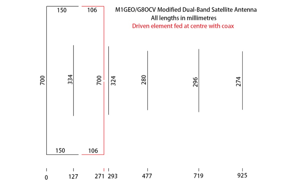 The antenna is a VHF side is a 2m moxon, tuned on 145.825 MHz. The driven element of the moxon couples to a driven element for a 5 element 70cms Yagi, tuned on 436.5 MHz.
 -
 A 6 dB gain Moxon rectangle antenna, designed for the 2-meter band, offers an excellent solution for hams seeking a compact, directional antenna for **SSB** operation, particularly in restricted spaces like an attic. This design emphasizes ease of construction using readily available materials such as 4mm OD brass tubing and plywood, making it an accessible project for many radio amateurs. The antenna's inherent characteristics, including a high front-to-back ratio of 37 dB and a 50-ohm feed impedance, contribute to its effectiveness in mitigating local noise and focusing radiated power. The project leverages the free MoxGen program for precise dimension calculations based on the desired frequency and wire size, and utilizes 4nec2 for pattern analysis, confirming a 3 dB beamwidth of 80 degrees. Construction involves bending brass tubing for the driven and passive elements, mounting them on an 800 x 350 mm plywood boom, and securing them with cable clips and epoxy resin. Initial SWR measurements at 144.3 MHz showed 1.6:1, which improved to 1.3:1 at 145.3 MHz across a flat band from 144.1 MHz to 145.5 MHz after adding a **coaxial choke** to mitigate common mode current.
 -
 The AE6AC 17-meter Moxon antenna project details the construction of a wire beam using readily available materials. This design utilizes four 16-foot fiberglass crappie poles for support, joined at the center with 3/4-inch Schedule 40 PVC pipe and "T" slip fittings. Wire segment lengths for 18.135 MHz were calculated using _Moxgen_ software by AC6LA, with specific dimensions provided in feet and inches for precise cutting. Key construction decisions include joining the crappie pole bases into a central hub and attaching the 16-gauge silver-plated copper wire to the pole ends. Dacron cord with a fisherman's knot secures the wire to the pole tips, while small wire loops at the corners maintain antenna shape. Plexiglas pieces serve as insulators for sections "A" and "C." The finished antenna, weighing less than 10 pounds, mounts on a fiberglass windsurfer mast and incorporates a 1:1 current mode ferrite bead balun. Performance measurements with an _MFJ-259B_ show an SWR better than 1.5:1 across the 17m band, with good front-to-back ratio and reported signal strength improvements of 2-4 S-units over vertical dipoles. Initial contacts included VK2AXB, ZF6GS, and KL1M.
 -
 Fabricates baseplate components, and provides hardware kits for DIY hex beam, spiderbeam and moxon antennas.
 -
 Constructing a compact, single-feed triband Moxon antenna for 20, 15, and 10 meters is detailed by DU1RZ, drawing from his personal experience with space-constrained antenna projects. Initially fascinated by cubical quads, the author transitioned to Moxon designs in 2005 after realizing his roof space was insufficient for a bulky quad. His first experimental monoband Moxon for 15 meters, built from repurposed materials, provided solid DX QSOs for seven years, despite being slightly below the 21 MHz band center. The project outlines the design process, including using the _MOXGEN Calculator_ for element dimensions and material selection, such as #14 AWG enamel copper wire and fishing poles for spreaders. DU1RZ shares insights from simulations with DL2GMS regarding insulated versus non-insulated wire performance, noting that insulated wire can shift resonant frequencies lower. The assembly instructions cover preparing wire elements, connecting feed points, and tuning the antenna, with initial SWR measurements taken at 10 feet and final readings on a mast showing excellent results: 1.0:1 on 14.225 MHz, 1.1:1 on 21.250 MHz, and 1.3:1 on 28.50 MHz. Transmission tests with 4F1BYN indicated a front-to-back ratio of approximately 2 S units with 10 watts output. The author emphasizes adaptability, encouraging builders to use readily available materials rather than strictly replicating his setup. Key observations from DU1RZ and DL2GMS highlight the antenna's strong performance across 20, 15, and 10 meters, good front-to-back ratio, full bandwidth on 20 and 15 meters, and its small turning radius of about 4.18 meters (13.54 feet), making it suitable for limited antenna space. Its lightweight construction and low wind load are also noted as significant advantages.
 -
 A project for a 50 MHz moxon rectangle antenna
 -
 Presents construction details for Moxon antennas, specifically focusing on 10-meter and 17-meter band configurations. It covers practical aspects of building these directional wire arrays, including element spacing, feedpoint considerations, and material choices for optimal performance. The resource emphasizes homebrewing techniques suitable for amateur radio operators. Discusses the advantages of the Moxon rectangle design, such as its compact footprint compared to a full-size Yagi and its favorable front-to-back ratio. It provides insights into achieving proper impedance matching and structural integrity for portable or fixed installations. The content includes photographic examples of constructed antennas. Explains the iterative process of tuning and optimizing Moxon antennas for specific frequency segments within the 10m and 17m bands. It offers guidance on minimizing SWR and maximizing gain, drawing from real-world building experiences to assist constructors in replicating successful designs.
 -
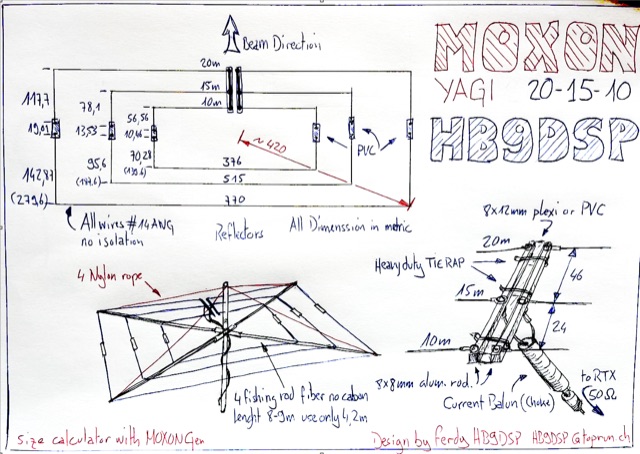 The QRZ.com callsign database serves as a fundamental resource for amateur radio operators worldwide, enabling rapid lookup of station information. Each entry, such as the one for _HB9DSP_, typically includes essential details for making and confirming contacts. Operators can find QSL routes, often indicating preferences like "via bureau or direct," which streamlines the exchange of QSL cards for award credit. Beyond basic contact data, these pages frequently offer insights into an operator's activities, including their participation in contests or DXpeditions. The platform also tracks metrics like "XML Subscriber Lookups," showing how often a callsign's data has been programmatically accessed, totaling **77670** for this specific entry. This functionality is crucial for logging software and other automated systems that rely on accurate, up-to-the-minute amateur radio data. While the page title mentions a "Home made multiband MOXON" antenna, the actual content primarily focuses on the callsign's biographical data within the _QRZ_ database.
 -
 Constructing an effective directional antenna for the 40-meter band presents unique challenges due to its physical size requirements. This resource details the homebrew construction of a 2-element _Moxon_ Yagi antenna specifically designed for 7 MHz operation. The author, TA7OM, provides a visual guide to building this antenna, showcasing the boom, element mounting, and feedpoint connections through a series of high-resolution photographs. While textual descriptions are minimal, the imagery clearly illustrates the mechanical aspects of the antenna's assembly. The _Moxon_ rectangle design offers a compact footprint compared to a full-size Yagi, making it a practical choice for many hams with limited real estate. The visual documentation allows builders to replicate the antenna's structure, including the use of PVC pipe for element support and the method for spacing the driven and reflector elements. The project emphasizes practical construction techniques for achieving a directional pattern on a challenging HF band, suitable for DXing and contesting.
 -
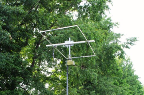 Design and build a 6 meter 2-element Moxon antenna mostly from available aluminum tubing and angle stock.
 -
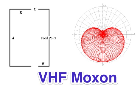 Constructing a 2-meter Moxon antenna for MURS channels, this resource details the antenna's geometry and expected radiation pattern. The design, optimized for low SWR, high gain, and front-to-back ratio on the first three MURS channels, uses 1/8-inch bronze brazing rod for elements. Author John E. Davis provides specific geometric parameters (A, B, C, D dimensions) rounded to the nearest 16th of an inch, along with a link to the final _.nec_ file for further analysis. Performance results show the attic-mounted Moxon performs well on the 2-meter band, despite its MURS optimization, with measured SWR plots provided. NEC-2 modeling predicts over 6 dBi gain and 40 dBi front-to-back ratio in free space. The author compares its directional performance to a _J-pole_ antenna, demonstrating substantially better signal strength for a nearby repeater when the Moxon is pointed in its general direction, confirming its superior gain and directivity.
 -
 This resource details the construction of a Moxon rectangle antenna, a two-element wire beam, drawing inspiration from a _QST_ article by Allen Baker, KG4JJH, and a project group led by KD6WD. It outlines the use of _AC6LA_ software for critical measurements (A-E) to design the antenna for specific bands like 17 meters, emphasizing the simplicity of adjusting frequency and wire size. The guide covers material selection for spreaders, such as telescoping fiberglass fishing poles, and various hub constructions, including aluminum tubing and PVC joints, with accompanying images. The author shares practical insights from building multiple Moxons for 10, 15, 17, and 20 meters, noting consistent 1:1 SWR at design frequencies and broadbanded performance. It describes the feedpoint assembly using a 1:1 Yagi current balun and wire nuts for robust, adjustable connections. The resource also discusses element insulators made from Lucite strips and attachment methods to spreaders using plastic wire ties and duct tape, ensuring precise element spacing. Performance observations include significant signal improvements (4-5 S units) over quad loops and a unique "DX-Vane" effect where the suspended antenna self-aligns with the strongest DX signal. The author also recounts an unsuccessful attempt at a dual-band 17/20 meter Moxon, concluding that the Moxon is inherently a monoband antenna, supported by _EZNEC_ plots for a 17-meter design.
 -
 The W6NL Moxon Yagi is a high-efficiency two-element 40m Yagi that uses cross elements to provide both loading and Moxon coupling, addressing the challenge of deploying a directional antenna on the 40-meter band. This resource details the transformation of a _Cushcraft XM240_ Yagi into this Moxon configuration, replacing the original loading coil LCA sections with four new assemblies. The guide provides comprehensive instructions for building the boom and elements, including specific dimensions for new sections and tee loading elements, along with detailed drawings and a full parts list for the conversion. Performance data indicates the converted antenna achieves **10.73 dBi** gain at 7.050 MHz with 99.5% efficiency and a high front-to-back ratio. The VSWR bandwidth is over **300 kHz**, ensuring good performance across a significant portion of the 40m band. Construction involves reinforcing element sections, attaching tee loading elements with U-bolts, and implementing element guying using materials like _Phillystran_ to manage sag and maintain structural integrity.
 -
 Constructing a compact directional antenna for the 17-meter band, this resource details the build process for a Moxon rectangle, a two-element Yagi variant with folded-back elements. It covers the antenna's evolution from the _VK2ABQ beam_ and provides specific dimensions for a version built using fishing pole whips. The content includes a discussion of the antenna's radiation pattern, feedpoint impedance, and its inherent front-to-back ratio, which is often superior to a standard two-element Yagi. Practical considerations for element spacing and material choices are also addressed, alongside a visual representation of the antenna's physical layout. Performance data presented includes a comparison showing the Moxon rectangle's **2.5 dB gain** over a half-wave dipole and a front-to-back ratio of **20 dB**. The resource also touches upon the antenna's relatively wide bandwidth for a two-element beam and its suitability for portable operations due to its compact footprint. It offers insights into optimizing the design for specific operating conditions and discusses the advantages of its lower take-off angle compared to omnidirectional wire antennas, making it effective for DX contacts on the 17-meter band.
 -
 Constructing a directional antenna for the 6-meter band (50 MHz) can significantly improve signal strength and reduce QRM during local ragchews or **Field Day** operations. This project details the assembly of a Moxon rectangle antenna, known for its compact size and respectable gain, making it a practical choice for portable or fixed station use on the magic band. The design utilizes readily available materials such as 14 AWG copper wire for the radiating elements and PVC pipe for the frame, ensuring an inexpensive build. The article provides specific dimensions and construction steps, allowing radio amateurs to replicate the antenna with confidence. It emphasizes achieving a low **SWR** across a bandwidth exceeding 1 MHz, crucial for efficient power transfer from the transceiver. Performance characteristics include a reported 5.5 dBi gain and a front-to-back ratio of 20 dB, offering effective directivity. The project also highlights the antenna's suitability for Field Day, where quick deployment and reliable performance are paramount for maximizing contacts.
 -
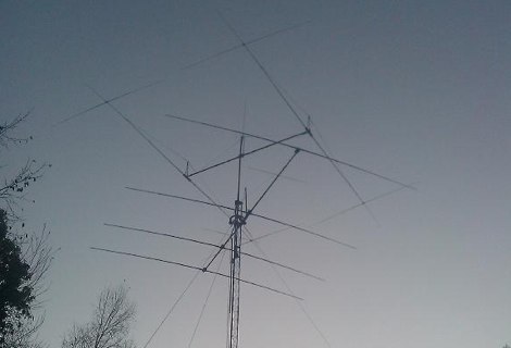 A project for a Moxon antenna for 7 MHz with pictures and EZNEC model
 -
 A 2m band Moxon antenna design is presented, centered at 145.2 MHz, with dimensions derived from Moxgen software. The design features a calculated 6 dBi gain, an 80-degree beamwidth, and an impressive 43 dB front-to-back ratio with minimal back lobes, concentrating RF energy in the forward direction. The antenna is balanced to 50 Ohms, facilitating direct feed. SWR sweep data from 144 MHz to 146 MHz demonstrates a near 1:1 SWR at the center frequency, maintaining healthy SWR values across the entire 2m amateur band. This performance is comparable to a 3-element Yagi, yet the Moxon offers advantages in compact size and ease of mast mounting, making it suitable for various operating environments.
 -
 A 50.200 MHz Moxon antenna for the 6-meter band is detailed, providing practical construction guidance for amateur radio operators. The design utilizes 3/4" aluminum angle stock for the elements, joined with wood molding and 1/4 x 20 hardware. Key components include an SO-239 connector for the feedpoint and a **choke balun** made from coiled RG-58 coax, ensuring proper impedance matching and minimizing common mode current. The antenna measures approximately 29 inches deep by just under 7 feet long, making it suitable for portable operations. Specific dimensions, based on **Cebik's nomenclature**, are provided for the driven element and reflector. The resource also offers modeling hints, suggesting an effective element diameter of 1 inch for software simulations and emphasizing element sizing based on corner screws rather than end-to-end measurements.
 -
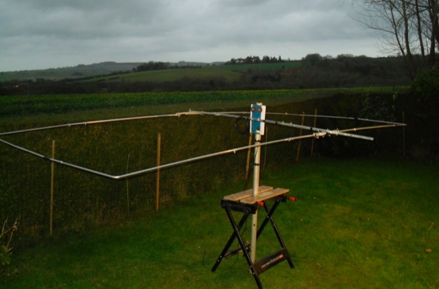 A page dedicated to servicing and building a 10 meter band moxon Antenna
 -
 The resource examines the operational characteristics and potential of Moxon Yagi antennas, drawing insights from Les Moxon's work and subsequent NEC modeling. It presents simulated current distributions and radiation patterns for a 40-meter Moxon, comparing its performance against a standard 2-element Yagi on the same band. Specific data points include forward gain, front-to-back (F/B) ratio, and feedpoint impedance, which are critical parameters for antenna design and optimization. Further analysis extends to a 20-meter Moxon, detailing its gain, F/B ratio, and SWR bandwidth across the band. The discussion highlights the Moxon's compact footprint and its ability to achieve respectable performance metrics, making it a viable option for hams with limited space. The content provides a technical assessment of the Moxon's advantages in terms of pattern purity and impedance stability compared to other compact directional arrays. The article also touches upon the practical considerations for constructing and deploying Moxon antennas, emphasizing the trade-offs between physical size and electrical performance. It includes graphical representations of antenna currents and radiation patterns, offering visual aids to understand the theoretical concepts discussed.
 -
 Over 150 pages of content are dedicated to maximizing activity on the 6-meter band, often referred to as the _Magic Band_. The resource details various propagation modes, including sporadic E, F2, and tropospheric ducting, providing insights into their characteristics and how to leverage them for DX contacts. It also covers essential equipment considerations, from transceivers and transverters to specific antenna designs optimized for 50 MHz operation, such as Yagis and Moxon antennas. The eBook presents strategies for participating in 6-meter contests and pursuing awards like _VUCC_, offering practical advice on logging software and operating techniques. It includes discussions on software tools useful for predicting propagation and managing contacts, alongside guidance on finding and utilizing DX maps to identify openings. The author, K5ND, shares his extensive experience to help operators achieve successful 6-meter DXing. Specific sections address the code of practice for 50 MHz operations and provide assistance in locating rare DX opportunities. The content is structured to guide both new and experienced operators through the nuances of the band, from initial setup to advanced operating strategies.
 -
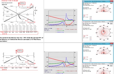 This page describes a comparison study on seven different beam antennas for 40 meters band. Yagi antennas, moxon antennas, mini horse all antennas are described with schema diagram , azimuth plot and SWR F/B Gain diagram
 -
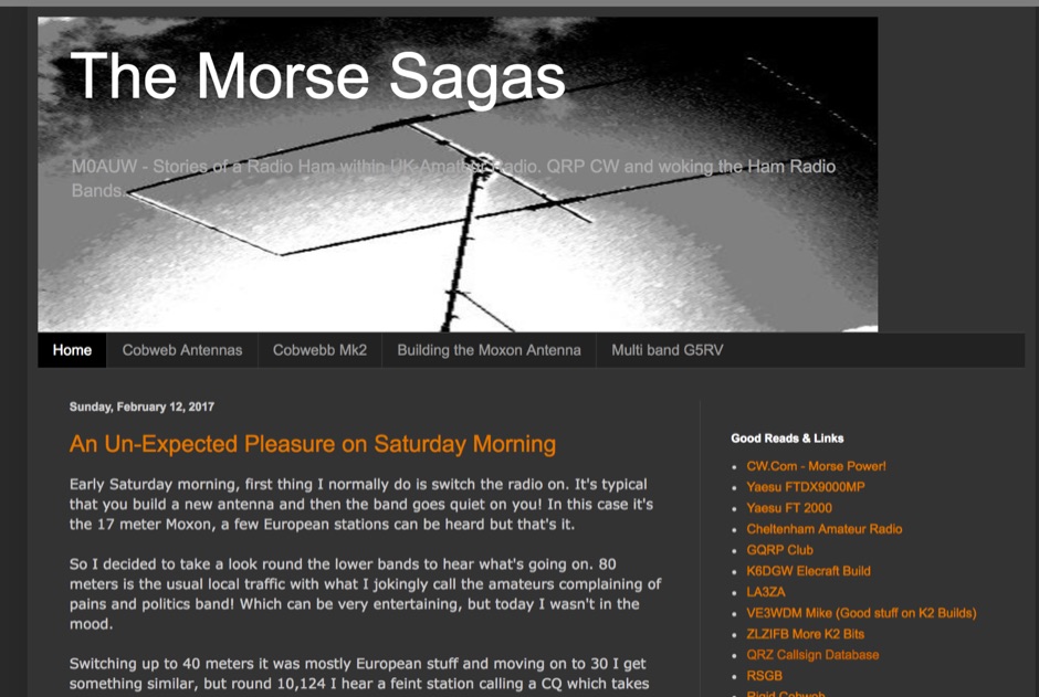 M0AUW's Amateur Radio blog specialising in Cobweb and Moxon antennas
 -
 This article is about a homebrew 6 meter lightweight Moxon antenna. Article includes a full part list, instruction to assemble the parts and pictures.
 -
 A W8JK/Moxon antenna variant with 400cm long monopoles is detailed, demonstrating a **1dbd** gain improvement over the traditional Open-Folded W8JK. This design, relying on the _Moxon principle_, achieves higher radiation impedance, leading to increased antenna efficiency and reduced losses. The article includes VNA output data for various HF bands, showing impedance characteristics from 10.1 MHz to 50.1 MHz, and provides NEC model wire definitions for the antenna structure. Field tests performed by F6IIV, Marc, compared his W8JK Moxon style antenna against a Cobweb antenna at the same height. Results indicated the W8JK Moxon variant provided a **6dB** (1 S-meter point) advantage on most bands from 20m to 10m, and a significant 10dB (1.5 S-meter points) advantage on 15m. The antenna features a 2.70m boom and a turning radius of less than 3 meters, making it suitable for limited space installations while maintaining bi-directional performance on most bands.
 -
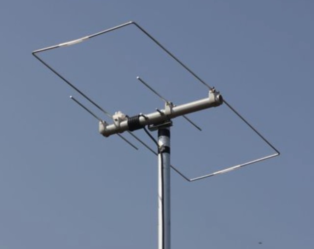 This small dual band UHF VHF directional antenna is good choice for portable operations. This antenna is composed by a moxon antenna for the two meters band and it includes two parastatic elements for 70 cm band.
 -
 Constructing a directional antenna for VHF operations, particularly for 2-meter band contests or local communication, often involves balancing performance with ease of build. The Moxon rectangle, a compact two-element beam, offers a good front-to-back ratio and gain in a smaller footprint compared to a Yagi, making it suitable for portable or temporary setups where space is limited. This design typically uses a driven element and a single reflector, bent into a rectangular shape to achieve its unique radiation pattern. The article details the construction of a 2-meter Moxon antenna, specifically for 144 MHz, utilizing readily available materials like PVC pipe for the frame and copper wire for the elements. It outlines the dimensions for the driven element at 970mm and the reflector at 910mm, with a spacing of 140mm between them, and a 50mm gap at the element ends. The feedpoint is a direct 50-ohm connection, simplifying matching requirements. The project includes a parts list, a basic diagram illustrating the element layout and dimensions, and photographs of the completed antenna. The author notes the antenna's performance during a QRP contest, achieving contacts up to 100km with 5 watts, demonstrating its effectiveness for low-power VHF work.
 -
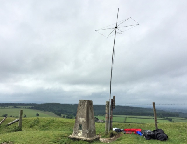 Bring the six meters with you during your hoilidays. This article features a portable moxon antenna for 50 MHz used for sota portable operatios
 -
 Presents the construction and performance characteristics of the _Moxon Rectangle_ antenna, a compact, directional HF antenna design. It details the antenna's physical structure, emphasizing its robust build and ease of erection compared to traditional Yagis. The resource provides specific dimensions for building Moxons for the 10m through 40m bands, derived from _W4RNL_'s work, and discusses the critical element spacing for optimal performance. It also covers feeding the antenna with a simple choke balun and achieving a low SWR across the band. Compares the Moxon's performance to a two-element Yagi, noting its superior wind resistance and compact footprint. The author, _VK3BCY_, shares personal experiences with a 20m Moxon, reporting SWRs below 1.3 across the entire band and strong signal reports from DX stations with only 100 Watts. EZNEC Pro modeling data is included to illustrate gain and front-to-back ratios, confirming the antenna's high-performance claims. The article also briefly explores multi-band possibilities and reversible configurations.
 -
 The DK7ZB-Dualband-Moxon-Beam provides a compact, high-performance antenna solution for 28 MHz and 50 MHz operations, utilizing a single 50-ohm feedpoint. This design functions as a mini-beam on 10 meters, achieving a gain of **4.0 dBd** with a front-to-back ratio of _30 dB_, while operating as a 2-element Yagi on 6 meters, yielding a gain of **4.3 dBd** and an 11 dB F/B ratio. The antenna's dimensions are approximately two-thirds that of a full-size 10-meter beam, making it suitable for smaller spaces. Construction details include a parts list specifying aluminum tubes of various diameters and lengths for the reflector and radiator elements. Builders like Aleks (S54S) and Marcio (PY2OK) have successfully replicated the design, with Aleks noting the utility of bending corners during assembly. Fine-tuning is accomplished by adjusting the length of specific elements that slide into larger tubes. The feeding system incorporates a balun, with options for either 300 watts using RG188 on an FT140-43 core or 1 kilowatt using _Aircell-5_ on an FT240-43 core, ensuring versatility for different power levels.
 -
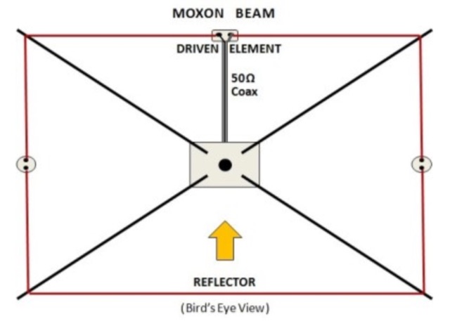 In this article the author feature the various types of beam antenna that can ben builw using wires, like moxon, spieder and hex beam, delta loops, bird yagi
 -
 In this article the author describes his personal experience on some antennas for 50 MHz he tested on the field, the six meter Dipole, Vertical, Moxon, a 3 element Yagi and an Omniangle antenna.
 -
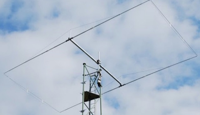 The author presents initial NEC model results for a reversible 40-meter Moxon antenna, comparing three distinct designs: a standard rectangle, a _W6NL short-tipped_ variant, and a T-hat configuration. All three models exhibit similar electrical performance, with gain figures around **5.5 dBi** and front-to-back ratios exceeding 20 dB. The primary differentiation among the designs lies in their mechanical construction and physical dimensions, which are critical for a 40-meter antenna. The rectangular Moxon requires robust support due to its element lengths, while the T-hat design offers enhanced structural integrity with slightly longer elements. The T-hat model is provisionally selected for further development, emphasizing the importance of mechanical considerations over minor electrical performance differences. Future work will focus on detailed mechanical design and construction aspects of the chosen T-hat configuration.
 -
 Presents an interactive online **Moxon antenna designer** tool, enabling radio amateurs to configure and analyze lightweight Moxon antennas for HF and VHF bands. Users can specify design frequency, element lengths, wire diameter, insulation, and support height. The tool visualizes the antenna in interactive 3D graphics and generates comprehensive performance charts, including azimuth, elevation, 3D, and polarization radiation patterns, VSWR charts, antenna current diagrams, and Smith charts. It also allows selection of various ground types (e.g., very poor soil, salt water, free space) to model environmental effects on antenna performance. The designer provides insights into how physical dimensions and ground conditions influence key antenna parameters like forward gain, front-to-back ratio, and feed-point impedance, which is typically close to 50 ohms. It also includes a feature to model the effect of coaxial cable losses on **VSWR** at the transmitter end, distinguishing it from the feed-point VSWR. This helps operators understand the actual radiated power efficiency versus the apparent match at the transceiver, offering a practical perspective on antenna system performance in portable operations.
 -
 Documents the design and construction of a **four-band Moxon beam** antenna, covering 20, 15, 10, and 6 meters. Author W7JMP shares his journey from initial research and computer modeling using 4NEC2 to the final on-air testing and optimization. The project aimed for gain over a dipole on 20 meters, with a budget under $500, including the antenna rotor. The design incorporates fiberglass spreaders and a single feedpoint, avoiding complex relay switching. The article details the selection of materials, assembly techniques, and the critical tuning process. W7JMP describes fabricating the hub, mounting spreaders, and attaching elements made from stripped THTN wire. A notable innovation is the use of a half-wave tuning stub with a loading coil for in-situ adjustment of the 20-meter reflector, optimized via remote S-meter readings using a webcam and smartphone. This method allowed for fine-tuning the **front-to-back ratio** without lowering the antenna. Initial testing revealed a dipole-like pattern, which was significantly improved after tuning, resulting in reported 2 to 4 S-unit front-to-back ratios and enhanced signal strength for DX contacts on multiple bands, including sporadic E on 10 and 6 meters.
 -
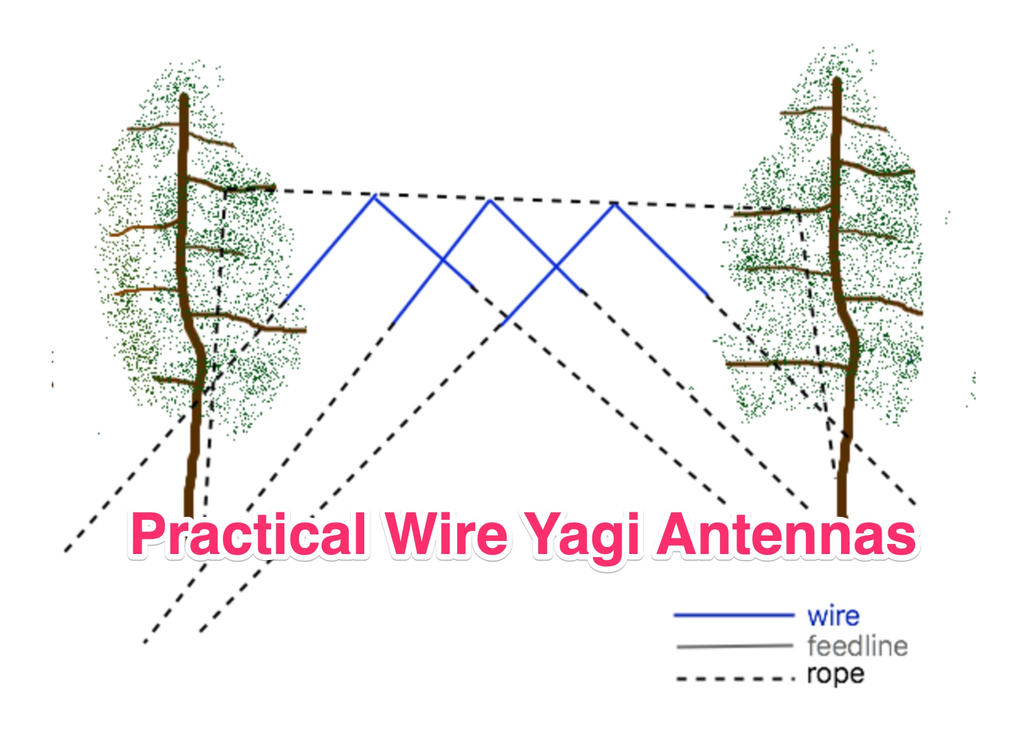 Learn how to build wire Yagi antennas for your ham radio setup. Discover how smaller wire elements can offer practical and portable options for temporary operations. Explore designs like the Hex Beam, Spider Beam, and Moxon that require less mechanical complexity and can be easily rotated or supported. Find out how to construct and hang wire Yagis from ropes, trees, or masts with inverted vees or horizontal elements. Get tips on element positioning, gain, and beamwidth considerations. Follow simple construction steps using a rope boom and marking element positions for efficient assembly. Enhance your ham radio experience with versatile wire Yagi antennas.
 -
 An ingenious portable satellite antenna designed for the IC-705. Addressing its lack of full duplex, the IC-705’s Split Mode enables FM satellite communication, with memory channels programmed for Doppler correction. The antenna combines a 2m Moxon and 70cm Yagi for mechanical simplicity and a single feed point, ideal for handheld use. Built with 3D-printed parts, TIG welding rods, and PVC pipe, it’s lightweight, transportable, and effective. STL files and detailed instructions ensure easy replication for enthusiasts.
 -
 Optimizing directional gain on the 40-meter band often involves complex antenna designs; this resource details the construction and performance of a reversible _Moxon_ array. The design provides directional coverage from southeast to west, with a switching mechanism to reverse the pattern towards east to northwest. Key design considerations include precise element spacing, the critical role of coil inductance for proper resonance, and the use of _NEC5_ for accurate electromagnetic modeling, ensuring the antenna performs as predicted across the desired frequency range. The antenna's performance is evaluated through on-air contacts, demonstrating effective signal propagation to regions like the Caribbean, South/Central America, the US, and Europe. The article presents measured SWR plots and gain patterns, comparing them against the _NEC_ model predictions to validate the design's efficacy. Practical application notes cover mounting considerations and the benefits of its reversible pattern for targeted DXing on 40 meters, offering a robust solution for operators seeking enhanced directional capabilities without a full-sized rotating Yagi.
 -
 Details the construction of a portable 6-meter 4-element quad antenna, specifically designed for VHF and Field Day operations. The design emphasizes portability and rapid field assembly, utilizing a 10-foot boom, #12 bare wire elements, and fiberglass electric fence post spreaders. It presents specific dimensions for reflector, driven element, and directors, including spreader lengths, circumferences, and corner marks, all derived from a G0KSC design and modeled in EZNEC. The resource outlines the fabrication of synthetic lumber hubs that allow post-assembly adjustments along the boom, and describes spreader clamps made from ¾” OD fiberglass rod, drilled and tapped for 8-32 nylon thumbscrews to secure element wires. It provides instructions for reducing spreader ends to 0.370” OD for proper fit and details the assembly of the boom from two 1½” OD x 6’ aluminum tubes. Performance data from EZNEC modeling indicates a gain of 10.25 dBi (8.1 dBd) and a 20 dB F/B ratio at 50.150 MHz, with SWR values of 1.08, 1.09, and 1.11 at 50, 50.15, and 50.5 MHz respectively. The document includes a field test report from Field Day 2010, where the antenna was deployed at 21 feet, showing an SWR resonance 200 KHz below EZNEC predictions. It notes successful 5-watt QSOs into New York and Canada from Tennessee, highlighting the antenna's excellent directivity and gain compared to a 4 dBd Moxon. The antenna breaks down into easily transportable components, including two 5’ boom sections, a 3’ boom connector, 16 spreaders, and four element/spreader clamp assemblies.
 -
 Fifty-one MHz operation, often called the "magic band," benefits significantly from a well-designed antenna, and this resource details the construction of a rigid 6-meter _Moxon antenna_ using common DIY store materials. The author, 4L/G8BAG, shares his experience with the 6m band, highlighting its potential for long-distance contacts, with single-hop sporadic E propagation enabling QSOs up to **2,500 km** and multi-hop contacts reaching **10,000 km**. The project emphasizes cost-effectiveness and durability, utilizing yellow gas pipe with an internal stainless steel lining for the antenna elements. The article provides specific dimensions for the Moxon rectangle, derived from the 12mm internal diameter of the gas pipe's steel core, rather than the outer plastic. It also details the use of white PVC water pipe for insulators and mounting, ensuring a tight fit with the yellow gas pipe. Initial testing with an MFJ antenna analyzer showed an excellent 1:1 SWR across the 50-52 MHz range, even when using 75 Ohm satellite cable as a feeder. The construction process is straightforward, involving cutting and bending the gas pipe, fitting insulators, and connecting the feedline. The author's successful on-air results, including a 1000 km contact with a temporary vertical, underscore the effectiveness of the 6m band and the Moxon design. The resource concludes with a note on exploring heavier gauge gas pipe for future 10m antenna projects.