Search results
Query: build a dipole
Links: 90 | Categories: 6
-
 Design and build an 6 m dipole antenna from aluminum, tubing, that resembles the active element of a yagi beam antenna.
 -
 A simple to build full length 20/40 dipole antenna to be used in inverted vee configuration
 -
 The resource details the construction of a multiband trap-style Inverted-V antenna designed for operation on 3.5 MHz, 7 MHz, 14 MHz, 21 MHz, and 28 MHz. It presents specific winding data for the traps, including the number of turns, wire gauge, and coil former dimensions, crucial for achieving resonance on the target bands. The document provides a parts list and a diagram illustrating the antenna's physical layout and trap placement. It outlines the process for building the traps using PVC pipe formers and specifies the required capacitor values for each trap. The design emphasizes a practical approach to achieving multiband operation with a single feedline, a common goal for HF operators with limited space. The document includes a table with antenna segment lengths for each band, allowing for precise replication of the design. It also offers insights into tuning and adjustment, ensuring the antenna performs optimally across the designated amateur radio bands.
 -
 Building a Resonant Feed line Dipole for 2 Meters
 -
 Amateur Radio 40m 20m 15m Half Wave Fan dipole antenna project with part list, pictures and drawing. Includes the option to expand the antenna to cover the 80 meters band
 -
 An easy to build dipole for 21 and 14 MHz with traps made by two T50-6 toroids cores mounted on a simple PCB foil
 -
 This article serves as a beginner-friendly guide to constructing a simple VHF dipole antenna for 2 meters, perfect for novices in the hobby. With an emphasis on affordability and simplicity, it explains the basics without overwhelming technical details. Recommendations for coaxial cable and mounting methods are provided, offering practical solutions for effective communication. By following these instructions, novices can build a functional antenna without breaking the bank.
 -
 Constructing a compact directional antenna for the 17-meter band, this resource details the build process for a Moxon rectangle, a two-element Yagi variant with folded-back elements. It covers the antenna's evolution from the _VK2ABQ beam_ and provides specific dimensions for a version built using fishing pole whips. The content includes a discussion of the antenna's radiation pattern, feedpoint impedance, and its inherent front-to-back ratio, which is often superior to a standard two-element Yagi. Practical considerations for element spacing and material choices are also addressed, alongside a visual representation of the antenna's physical layout. Performance data presented includes a comparison showing the Moxon rectangle's **2.5 dB gain** over a half-wave dipole and a front-to-back ratio of **20 dB**. The resource also touches upon the antenna's relatively wide bandwidth for a two-element beam and its suitability for portable operations due to its compact footprint. It offers insights into optimizing the design for specific operating conditions and discusses the advantages of its lower take-off angle compared to omnidirectional wire antennas, making it effective for DX contacts on the 17-meter band.
 -
 An easy to build and extremely high performance antenna, works perfectly on all HF bands 3.5-28 MHz with some compromises, it is basically an half wave dipole for 40-80 meters, an LC circuit or trap 40 meters allows you to use a single radiating element.
 -
 How to build Fan-Dipoles by DK7ZB. Experiences with various band combinations. Not all combinations are working properly. If the frequencies are to close together the impedances will lead to a very bad SWR. This happens with the bands 10-12-15m or 15-17-20m.
 -
 Full article on how to build a home-made wire dipole antenna for 40 and 80 meters band. Article is fully in italian, as it was published on ARI RadioRivista, but is plenty of self explaining pictures that will guide you on homebrewing this trapped dipole antenna for the lower amateur radio bands.
 -
 Experimenting a 20 40 meter short coil loaded dipole antenna with the goal to keep the total length under 40 feet so that the dipole can be mounted on two 20 foot fiberglass pole to make a 20/40 meter rotatable dipole.
 -
 An experimental prototype of an asymmetrical hatted vertical dipole antenna that can work on HF bands 20 to 10 meters band. The AHVD Vertical dipole is an upside-down T design
 -
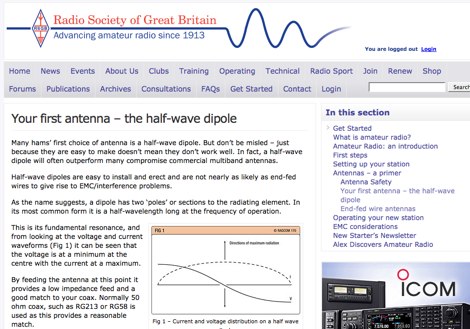 RSGB article for beginners. How to build a dipole antenna, construction tips and correct setup of inverted-ve dipole antennas
 -
 One of the featured products, the V350 CAMP, is a multiband vertical antenna covering 6 to 80 meters, priced at R$ 799,90, demonstrating the range of ready-to-use solutions available. The inventory includes various antenna types such as **HF**, **VHF**, and **UHF** designs, along with dual-band options like the J-Pole Dual V/UHF for R$ 235,00. For those building their own arrays, the store stocks essential components like element holders, clamps, junction boxes, and aluminum plates, alongside specialized items such as the KIT Isolador Central Dipolo - 01DX for R$ 99,90. The shop also provides a comprehensive selection of installation hardware, including diverse antenna mounts, PTT supports, and various coaxial cables like RG58 and RG213, with prices up to R$ 849,90 for RG213. Connectors such as UHF male PL259 and various adapters are readily available, ensuring compatibility for different setups. Additionally, specialized items like side handles for popular transceivers such as the FT857/891 and IC7300 are offered, catering to specific equipment needs. Beyond antennas, the store supplies practical accessories like transport bags, 12V power cables for transceivers, and even branded merchandise like the Antena Kit mug. Rodrigo Gonçalves, PP5BT, manages the operation from Blumenau, SC, Brazil, providing direct contact via WhatsApp at +55 47 9.9985.0155.
 -
 Dipole antennas are some of the simplest antennas to build in addition to being very efficient and solid performers. I wanted to make a simple dipole antenna for QRP portable operation that could be used on multiple bands.
 -
 A balun is a MUST for dipoles or similar antennas when they are feed with coaxial cable. From the RF point of view, the shield can be modeled as two conductors, the internal shield (the real shield, this is, ground) and the external shield, who is really far to be ground. In this way, your dipole has 3 arms, the two from the dipole and the coaxial cable shield (external face)
 -
 This article demonstrate how to build and mount a 40 meter loaded dipole using basic materials. This antenna reduce the overall length of an HF dipole through the use of loading coils.
 -
 This type of antenna is a popular antenna design as the performance is very good across the HF bands and requires little or no tuning. It’s a dipole fed off center with a 4:1 balun at the offset feed point. The antenna shown covers 80, 40, 20 and 10 meters. The formula can also be used to adjust the overall length to cover more or fewer bands and the resulting overall length. 160-10m, 80-10m or 40-10 meters depending on your available space. Other bands will require a tuner.
 -
 Building A Full-Wave Quad Loop Antenna for 6 Meters. This is an easy antenna to build and the materials cost about $15-20. It exhibits 1.8dB gain over a 1/2-wave dipole. Using an open-wire parallel feedline (commonly called ladder line) with an antenna tuner, it tunes up on the 10m band as a 5/8-wave loop as well
 -
 A 3 band dipole antenna for 40-80-160 meter bands, It's made with easily available materials and is designed for inverted V mounting. The antenna is shortened for these bands, but still manages to make contacts in 80m and 160m with stations in Canada and the USA. The construction details are provided, including the dimensions of the antenna elements and the traps. The antenna is easy to build and provides good performance in all three bands. In Italian.
 -
 This article describes a multi-band antenna design for amateur radio enthusiasts by G3FEW. The antenna is designed to cover at least five HF bands with low SWR and without the need for an ATU. It is also designed to be easy to construct and adaptable for different locations. The antenna is a full-wave dipole with traps at the quarter-wave points. The traps are used to tune the antenna to different bands. The antenna can be fed with a 4:1 balun. The article includes instructions for building the antenna, as well as information on the theory behind its operation. The author also discusses the results of his tests with the antenna. This multi-band antenna is a well-designed and versatile antenna that can be used by amateur radio enthusiasts on a variety of bands. It is relatively easy to construct and can be adapted for different locations.
 -
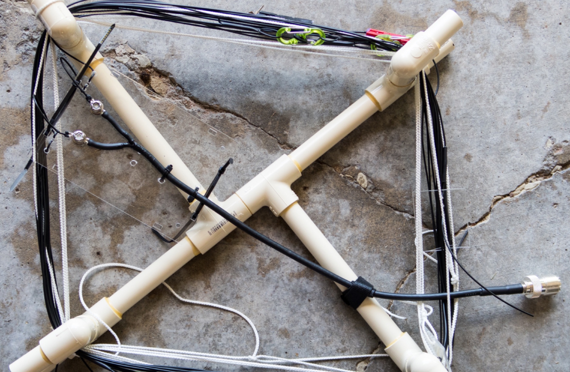
 The CobWebb antenna project is a compact, multiband HF solution ideal for amateur radio operators. Covering 14-28 MHz, it features a square dipole array with near-omnidirectional coverage and unity gain. This guide details a DIY approach, using a 1:4 current balun for impedance matching. Construction involves aluminum and fiberglass tubing, with optimized element tuning for SWR performance. Weather resistance improvements and resonance shift considerations are also discussed. Build your own CobWebb antenna for an efficient, space-saving HF experience.
 -
 Building an 80-160 meter antenna in a small garden (9m x 14m) involves creative solutions due to space constraints. This project outlines the construction of a trapped 80-160 meter vertical dipole, utilizing a crank-up tower and an 11-meter fiberglass pole. The design prioritizes minimal visibility, ease of construction, and cost-effectiveness, achieving effective operation despite limited space.
 -
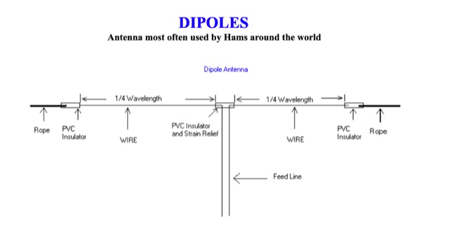 Antenna most often used by Hams around the world. Inexpensive, effective and easy to build, what more could anyone ask for in a home made antenna.
 -
 This page presents an online calculator tool for determining the dimensions of various HF wire antennas operating between 1.8-30 MHz. Users input their desired resonant frequency to obtain precise measurements for four popular antenna types: standard flat-top dipole, inverted Vee, quad loop, and equilateral delta loop. The calculator provides comprehensive measurements including leg lengths, minimum heights, horizontal spreads, and feedpoint distances. Accompanying the calculator are detailed technical explanations, construction notes, and installation guidelines for each antenna type, making it a practical resource for amateur radio operators building their own antennas.
 -
 Building an End-Fed Half-Wave (EFHW) antenna from a kit, as detailed by Frank Bontenbal, PA2DKW, with process photos by Bob Inderbitzen, NQ1R, offers a practical approach for hams. This specific kit, a collaboration between ARRL and HF Kits, targets 10, 15, 20, and 40 meters, making it a versatile option for HF operations. Unlike a center-fed dipole, the EFHW is a half-wavelength antenna fed at one end, which simplifies deployment, particularly for portable use. The construction guide meticulously outlines the assembly of the 49:1 impedance matching network, crucial for transforming the antenna's high impedance (around 2,500 Ohms) to a transceiver-friendly 50 Ohms. Steps include preparing the enclosure by drilling holes for the coaxial connector and antenna connections, followed by the precise winding of enameled copper wire onto a toroid to create the transformer. The guide emphasizes careful insulation removal and soldering for reliable connections. Final assembly involves integrating a 100 pF capacitor for higher band compensation, soldering the transformer's primary and secondary sides, and conducting SWR tests with a 2K7 resistor or a half-wavelength wire. The document also provides examples of wire lengths for different bands, such as 16 feet for 10 meters or 66 feet for 40 meters, demonstrating the transformer's adaptability for various half-wavelength configurations.
 -
 Dipole for 40m band. It is a simple linear loaded dipole feeded with 450-Ohm openwire feedline. Designed it for resonance at 7.050 MHz, can be tuned on 30m and 80m bands with an external antenna tuner. Build with simple electrical copper wire (2.5 mmq/13 awg) and two fishing poles with size of about 7 m/23 ft.
 -
 Build a low-cost 20m shower rod dipole antenna
 -
 A rotatable 40-meter dipole antenna designed and constructed to fit within backyard constraints. The project utilized two fishing poles attached to a fiberglass center pole, resulting in an easy-to-build, lightweight, and cost-effective antenna. Essential materials included fishing rods, a center support pole, mast support, and basic tools. Linear loading was implemented to achieve the necessary length for optimal performance. The antenna, which proved effective during the contest, is ideal for field days and additional contest bands. Assembly and installation were straightforward, showcasing the antenna's practicality and efficiency.
 -
 This document provides a detailed guide on constructing and mounting a folded dipol for the 146 MHz frequency in a vertical configuration to be used in Yagi antennas. The step-by-step instructions and diagrams included make it easy for hams to build and set up this type of antenna. Understanding and implementing this design can enhance the performance of radio communication for Amateurs operating in the 2-meter band. Whether you are looking to improve your signal strength or experiment with antenna designs, this resource offers valuable insights and practical information.
 -
 The article details the design and construction of a four-band Moxon beam by a radio amateur. The beam, mounted atop a rooftop tower, aimed for gain over a dipole on 20 meters, cost under $500, and included additional bands. The design features fiberglass spreaders, four bands (20/15/10/6 meters), and a single feedpoint. The construction involved computer modeling, NEC source code, and specific dimensions. The article outlines the assembly, materials, and tuning process, including in-situ adjustments for optimal performance. Despite initial challenges, the beam improved signal strength and facilitated contacts on multiple bands, marking it as the best HF antenna the author has owned.
 -
 This DIY homebrew project provides a durable, weatherproof center connector for dipole antennas, ideal for HF setups like 40m wire dipoles or inverted-V designs. Made from PVC pipe and an SO-239 UHF connector, it ensures strong support and room for a current balun. With simple drilling and assembly, it offers a cost-effective alternative to commercial options. Perfect for amateur radio operators, this dipole antenna connector enhances performance while keeping costs low. A great solution for DIY antenna builders seeking reliability and longevity.
 -
 A small magnetic loop antenna, often employed by hams facing antenna restrictions or high local RFI, offers a compact solution for HF operation. This resource details the construction of a foldable magnetic loop designed for the 40m through 17m bands, emphasizing its high-Q factor and _Faraday coupling_ for effective noise rejection and narrow-band filtering. The guide outlines material selection, advocating for copper over aluminum to maximize efficiency, and provides insights into the physics governing its operation, including impedance matching and resonance principles. Practical application of this antenna design is particularly beneficial for QRP enthusiasts and portable operators seeking a stealthy, high-performance antenna. The construction process includes specific details for a 1-meter diameter loop, a 140pF variable capacitor, and a _gamma match_ for impedance transformation. Performance comparisons suggest that while a full-size dipole might offer slightly better gain, the magnetic loop's ability to mitigate local noise often results in a superior signal-to-noise ratio, making it a viable option for challenging RF environments.
 -
 This article details the author's process of designing and building a trap dipole antenna for the 17, 12, and 6-meter amateur radio bands using a Yaesu FT-450 transceiver. The antenna incorporates parallel-tuned circuit traps to enable operation across multiple bands without switching aerials. Key construction details, including coil and capacitor specifications, are discussed, along with the testing results, which include successful long-distance communications on the 50 MHz band. The article highlights the flexibility of home-built antennas and provides insights for amateur radio enthusiasts looking to optimize multi-band performance.
 -
 This page provides detailed information on the 4DX directional wire beam antenna designed by LZ1AQ, LZ1ABC, VK6LW, and DD5LP. It explains how to create this antenna for single or multiple bands using four separate sloping wires. The page includes instructions on achieving directionality, gains, and F/B ratios, as well as generating radiation patterns, VSWR charts, antenna currents diagrams, and Smith charts. It is a valuable resource for hams interested in building and optimizing their own directional wire beam antennas for improved performance and long-distance contacts.
 -
 This document provides comprehensive guidance on modeling and constructing multiband dipole antennas using traps. It addresses common segmentation issues in EZNEC modeling software, recommends optimal segment lengths for trap models, and compares trapped dipoles with paralleled multiband dipoles. While trap dipoles are significantly shorter, they exhibit lower gain and narrower bandwidth. Detailed instructions for building weatherproof coaxial traps include material lists, construction steps, and tuning methods. The guide notes that properly constructed coaxial traps introduce only minimal signal loss (0.6 dB) while offering practical multiband performance in a compact design.
 -
 Learn how an experienced ham radio operator rebuilt his trap dipole antenna for 30, 40, and 80 meters after a storm damage. Discover the process of upgrading to a short trap dipole for 40, 80, and 160 meters using double-wound traps made from RG-58 coax. Follow along for construction details and tips on building this unique classi.
 -
 This page provides information on how to design an Off-Center-Fed Dipole (OCFD) antenna, suitable for amateur HF bands like 80 meters or 40 meters. The antenna design allows for VSWR minima on multiple bands, making it a good choice for multi-band use. Learn how to create an OCFD antenna in either flat-top or inverted-Vee form using a single support. The page also offers tools to generate radiation patterns, VSWR charts, and antenna current diagrams for your specific antenna design, helping hams understand performance factors. Ideal for ham radio operators looking to build their own effective antennas.
 -
 This article describes the design and construction of a 4-meter band vertical sleeved dipole antenna, built to complement a newly acquired Yaesu FTDX10 transceiver. The simple yet effective antenna consists of modified coaxial cable housed in weather-resistant plastic conduit, featuring an integrated 8-turn choke coil. Despite common misidentification as an EFHW antenna, this design is actually a sleeved dipole that provides an excellent 50-ohm match across the band, achieving SWR values between 1:1 and 1.1:1. The project demonstrates an economical approach to entering the relatively quiet 4-meter band.