Search results
Query: super radio
Links: 62 | Categories: 2
-
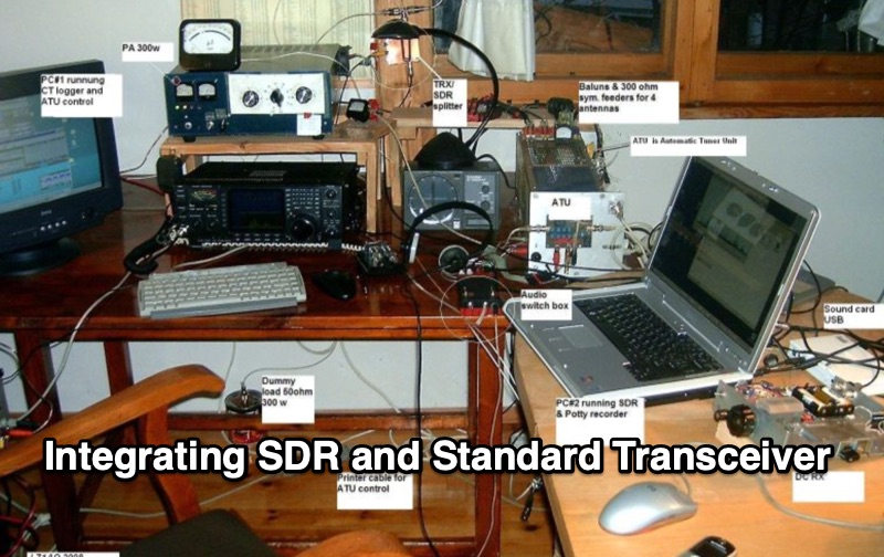 Integrating a _Software Defined Radio_ (SDR) into an existing ham radio setup involves connecting it with a standard transceiver (TRX), power amplifier (PA), and antennas. The core component is a splitter box that facilitates the connection between the TRX and the SDR, allowing for simultaneous operation without modifying existing equipment. In receive mode, the splitter ties the antenna inputs of both the TRX and a direct conversion receiver (DC RX) together. During transmission, the DC RX input is grounded via a fast telecom relay controlled by the transceiver's -SEND signal, incorporating a 10ms delay for safety. The splitter box includes a 3.7 dB input attenuator for impedance matching and acts as a protective fuse for the DC RX input. Ground loops are mitigated using common mode balun transformers, while the DC RX input is insulated with a broadband transformer. An audio switch box complements the setup, enabling users to listen to either the main transceiver, the SDR output, or both simultaneously. This configuration ensures noise immunity and safety, with the splitter housed in a screened box made from PCB material. On-air tests, such as the CQ WW 160m CW DX Contest, demonstrate the system's effectiveness, showcasing the SDR's ability to handle crowded band conditions with superior selectivity and dynamic range. The SDR's narrow bandwidth filters and waterfall display provide significant advantages, allowing operators to detect weak signals amidst strong interference. The integration of SDR with conventional radios offers enhanced operational flexibility and performance in challenging environments.
 -
 A homebrew spectrum analyzer, the Specan, provides a crucial measurement capability often missing from the typical amateur radio shack, allowing for detailed analysis of RF signals up to 70 MHz. This double-conversion superheterodyne receiver design incorporates 112 MHz and 12 MHz intermediate frequencies, utilizing an _Si570_ as the local oscillator for fine tuning down to 1 Hz steps. It offers two resolution bandwidths: 300 KHz for broad spectrum sweeps and 1 KHz for precise close-in distortion measurements, achieving an 80 dB spur-free dynamic range at 1 KHz resolution. The project, a reboot of the classic _W7ZOI/K7TAU_ design from November 1998 QST, integrates an _Arduino_ microcontroller for controlling the Si570, managing a front-panel LCD, and communicating with a PC for spectrum plotting. This approach significantly reduces cost compared to commercial units, making advanced RF diagnostics accessible to homebrewers. The Specan can measure carrier suppression, VFO cleanliness, antenna VSWR, transmitter harmonics, and filter passband shapes, providing insights beyond what an oscilloscope or frequency counter can offer. Construction emphasizes modularity and careful shielding, with each stage built and tested individually on unetched copper clad board. The design includes detailed instructions for integrating the Arduino, building the Si570 oscillator, and aligning the various modules, often using the Specan itself for calibration. It requires a well-regulated linear power supply and can be built with common tools and readily available components, making it a practical and rewarding endeavor for those looking to enhance their RF test bench.
 -
 Direct conversion receivers (DCR) are gaining renewed interest due to advancements in semiconductor technologies and their suitability for integration in compact, low-cost, multi-standard applications. Unlike traditional superheterodyne receivers, DCR eliminates image frequencies and bulky off-chip filters but introduces challenges like DC offsets, nonlinearity, and noise issues. This tutorial explores DCR's historical development, compares it with other receiver architectures, and addresses its inherent obstacles. DCR's potential for integration and compatibility with software-defined radio highlights its role in modern communication systems despite its technical complexities.
 -
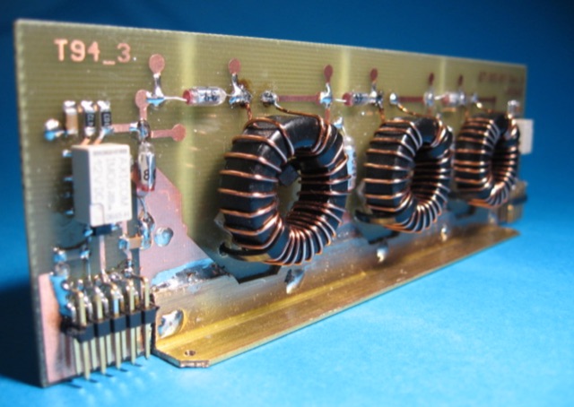 This article explores the nuanced design challenges of Band Pass Filters (BPF) in radio receivers, balancing low insertion loss, high stop band rejection, and narrow bandwidth. The focus is on the "Series-Trap, Shunt-C" topology, resonator count impact, and meticulous layout design for superior stop band performance across various frequency bands
 -
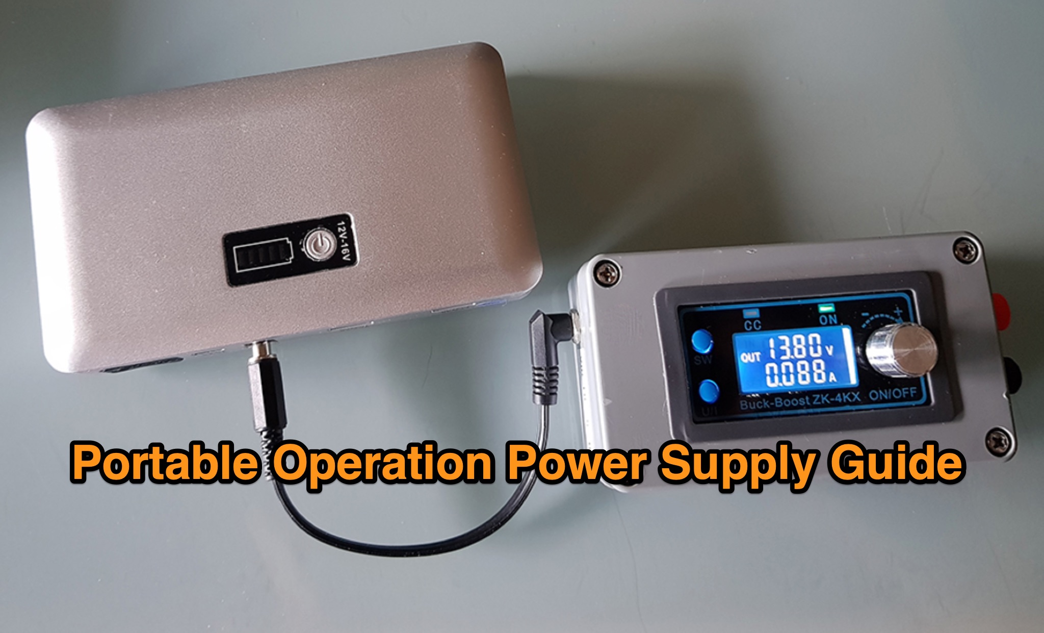 The _Icom IC-705_ portable operation power supply guide details the use of a car battery jump starter and a step-up/down converter for field power. It examines various power supply types, including LiFePO4 batteries, lead-acid batteries, and supercapacitors, discussing their respective advantages and disadvantages for QRP and portable setups. The resource emphasizes practical considerations such as capacity, weight, discharge rates, and charging methods crucial for reliable off-grid operation. The article compares the energy density and cycle life of different battery chemistries, noting that LiFePO4 batteries offer significantly more cycles (e.g., **2000-5000 cycles**) compared to lead-acid batteries (e.g., **300-500 cycles**). It also touches upon the integration of solar panels for recharging and the importance of proper voltage regulation to protect sensitive radio equipment, providing insights into maximizing operational time during DXpeditions or POTA activations.
 -
 Details the construction of a Copper Cactus Dual-Band Super J-Pole Antenna, providing specific measurements for 1/2-inch copper tubing sections, including a 57-1/2-inch long section and a 19-inch short section, along with a 42-inch piece of 3/16-inch or 1/4-inch soft copper tubing for the matching stub. It covers soldering techniques for copper fittings, drilling an SO-239 panel mount coaxial fitting, and securing feed point connections with stainless steel adjustable band clamps. The resource specifies materials such as Schedule M 1/2-inch copper tubing, various copper fittings, a hardwood dowel or Fiberglas rod for insulation, and #14 stranded copper wire for the feed point. The guide simplifies the J-pole feed point by using an SO-239 fitting with an elongated mounting hole and band clamps, noting an optimal feed point distance of approximately 3 inches above the crossbar for proper impedance matching. It recommends a 4-turn coax choke, 5 inches in diameter, placed within 3 to 4 inches of the feed point for 2-meter operation to mitigate RF on the feedline. The project emphasizes weather sealing with silicon or butyl rubber compound and clear lacquer for durability and appearance.
 -
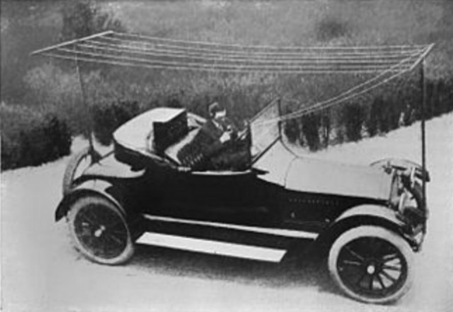 his historical account traces the development of car radios from Marconi's mobile wireless telegraph station on a steam engine vehicle in 1901 to Motorola's iconic car radio models in the 1930s. It highlights key milestones such as Alfred Grebe's radio-telephone experiments on Long Island and the introduction of Marconi-Phone 8 radios by the Daimler Company in England. The narrative explores technological advancements, including the transition from TRF to Super-Heterodyne circuitry and the integration of push-button controls. The evolution from vacuum tubes to transistors and compact discs is also documented, showcasing the continuous innovation in automotive entertainment systems.
 -
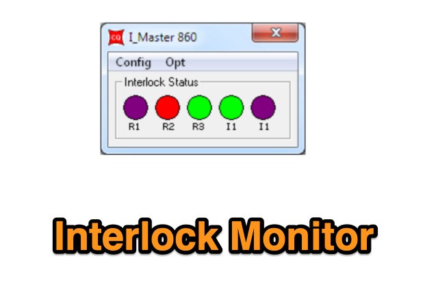 The Interlock Monitor (IM) program allows you to control and monitor the Interlock device from any computer in your network. The Interlock is an equipment designed to be used by contesters where they need to check, supervise and limit, how many radios are in transmission at any given time
 -
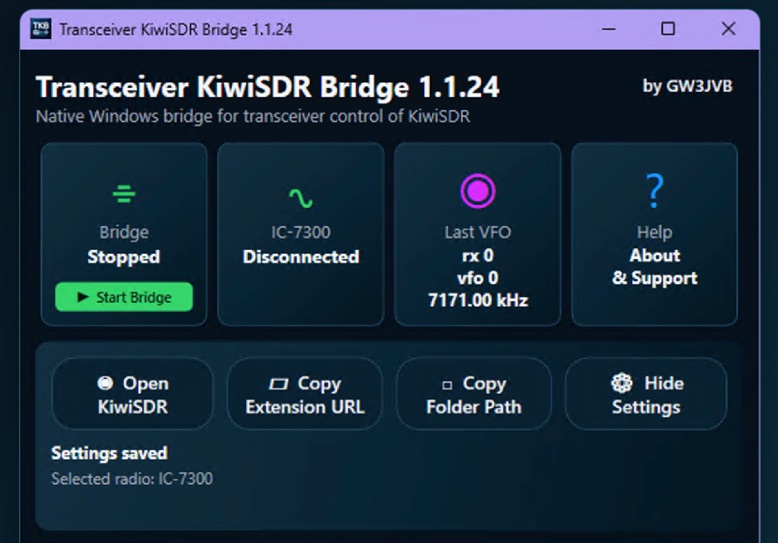 Demonstrates a practical solution for remote reception, the Transceiver-KiwiSDR Bridge, a free Windows utility by GW3JVB. This software links a local amateur radio transceiver to a remote **KiwiSDR** receiver, allowing the KiwiSDR to automatically track the transceiver's VFO frequency and mode. This capability proves invaluable for mitigating local noise, enhancing reception, or simply leveraging the superior receive capabilities of a remote station located globally. The bridge supports a diverse range of transceivers through COM port/CAT connections or **TCI** over a network. Specific compatibility extends to popular models like the Icom IC-7300, systems utilizing the TCI Protocol (such as Thetis, Expert Electronics, Apache Labs ANAN, and Hermes Lite 2), and many radios supported by Hamlib. Experimental Yaesu CAT options are also included, broadening its utility for various shack configurations. Key features encompass automatic mode changes, updates to RX filter bandwidth, and even IC-7300 PBT/filter adjustments. The application integrates a browser extension for Chrome, Brave, and Microsoft Edge, and offers an optional KiwiSDR audio mute during local transmission, ensuring a seamless operating experience. The compact view keeps the interface unobtrusive, with full settings readily accessible.
 -
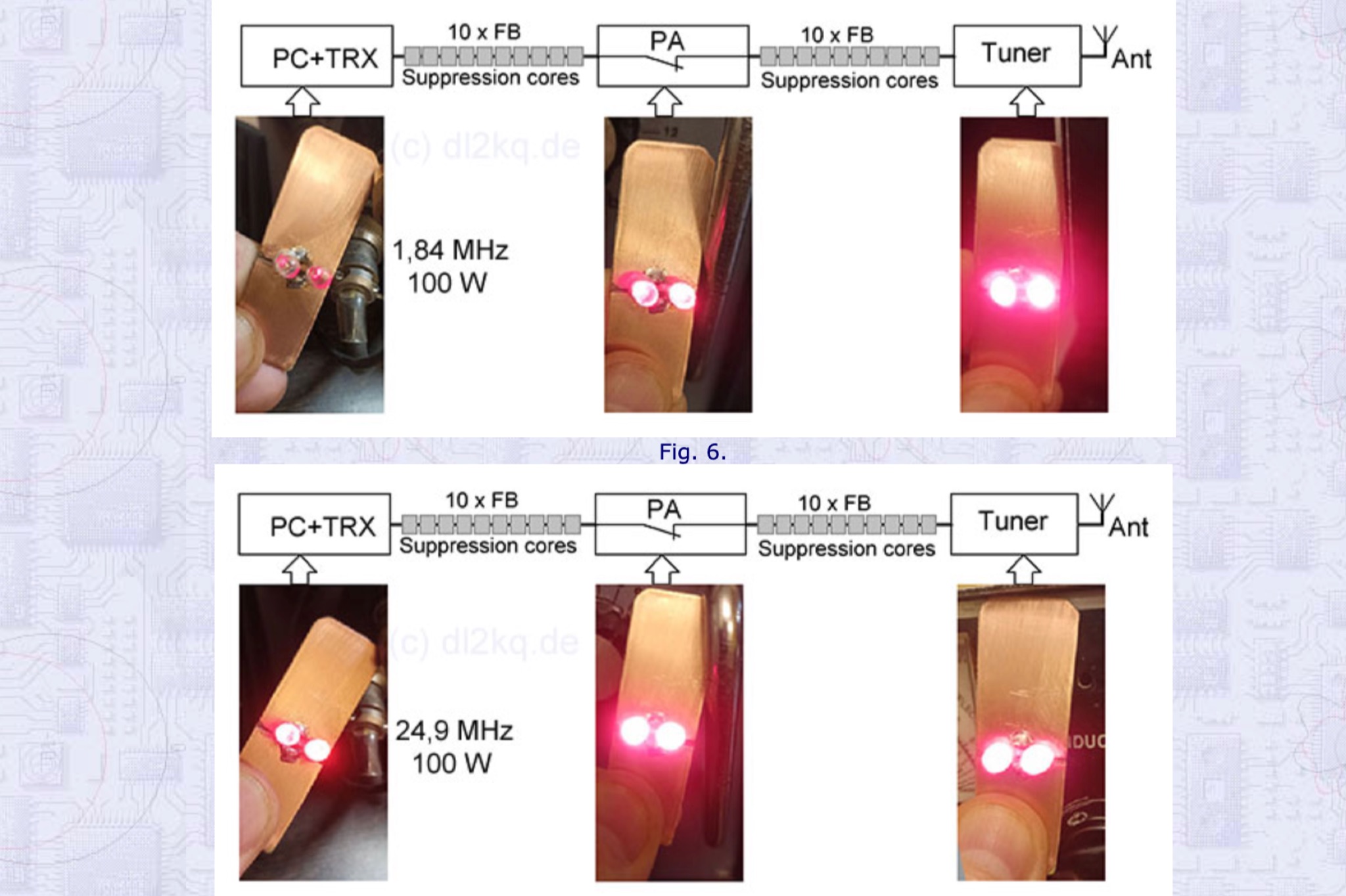 Detecting stray RF voltages on station grounds, chassis, and interconnecting cables is crucial for preventing program and hardware failures in the shack. This article details the construction and application of an LED RF V-probe, which offers significantly higher sensitivity compared to conventional neon lamp indicators. The probe leverages two specific properties of modern red LEDs: their ability to glow at microampere currents and their rectification capability at frequencies up to tens of megahertz. The design features a simple circuit with two LEDs, allowing for indication of both positive and negative RF voltage half-waves. The minimum detectable RF voltage is approximately 2 V, a substantial improvement over the 40-60 V threshold of neon bulbs. The resource illustrates the probe's physical construction on a PCB and provides a direct comparison demonstrating its superior sensitivity in detecting RF fields near a coil. Two operational modes are described: a non-contact mode for high RF voltages (above 15-20 V) and a direct-contact mode for measuring lower RF voltages, with a safety caution for the latter. Practical examples show the probe's use in analyzing RF voltage distribution across a radio station setup at 1.84 MHz and 24.9 MHz, revealing insights into common-mode current issues and the effectiveness of mitigation strategies like adding radials.
 -
 The UHF J-Pole antenna described here utilizes an aluminum angle bar and 4mm galvanized threaded rod for its construction, with dimensions based on a previously published design. Assembly involves drilling the angle bar, securing threaded rod sections with nuts, and connecting the coaxial cable via cable lugs, ensuring the braid connects to the shorter element. ROS adjustment is achieved by manipulating nuts approximately **30mm** from the angle bar, allowing for fine-tuning of the impedance match. Once optimal tuning is established, _super glue_ is applied to seal the coaxial cable ends and protect the threaded rod cuts from corrosion, enhancing durability. This project emphasizes rapid realization with common hardware, providing a practical solution for radio amateurs seeking a simple yet effective antenna for the 70cm band.
 -
 The Spartan Sprint Special 40m CW Transceiver, originally documented in 2002 and reproduced in 2019, details a **QRP** direct conversion rig designed for portable operation. This project evolved from an experimental CMOS digital IC receiver, which proved too noisy for weak signals, into a dedicated 40-meter CW transceiver. The author, VE3SMA, aimed for reduced size, lower weight, and decreased receive current drain compared to earlier iterations, drawing on his extensive contesting experience and even his time operating million-watt transmitters at Radio Canada International. This compact transceiver delivers approximately 200 mW output, VFO-tunable over 15 kHz within the 40m band, and weighs a mere 73 grams (0.16 lb) including its balsa wood case. It features fast semi-break-in and sidetone, with a receive current draw of about 14 mA (no signal) and transmit current draw around 125 mA key down. The design incorporates various construction techniques, including knife-cut surface mount boards and through-hole components, often salvaged from junked cordless phones and cellphones. Despite its direct conversion architecture, which offers usable but not superheterodyne-level selectivity, the rig proved effective, achieving a fourth-place finish in a June 2001 Spartan Sprint contest when paired with a 26-foot vertical antenna. The article provides comprehensive circuit details, including an unconventional VFO using a high-speed CMOS inverter chip and a balanced mixer utilizing a 74HC4053.